Format: PDF (Printable Document)
File Language: English
File Pages: 381
File Size: 38.55 MB (Speed Download Link)
Brand: Komatsu
Model: D475A-8 D475Ai-8 Bulldozer
Book No: GEN00285-02
Serial No: 50001 and up
Type of Document: Field Assembly Manual
$ 39
FOREWORD
CONTENTS
PRECAUTIONS FOR FIELD ASSEMBLY
DISPOSAL OF REMOVED PARTS
ASSEMBLY PROCEDURE, NECESSARY EQUIPMENTS, AND SCHEDULE
KIT LAYOUT DIAGRAM (WORK SPACE LAYOUT)
PACKING STYLE FOR TRANSPORTATION
SPECIFICATIONS
TOOL LIST FOR FIELD ASSEMBLY
DIAGRAM FOR TOOLS
TIGHTENING TORQUE TABLE
COATING MATERIALS LIST
SELECTION OF WIRE ROPES USED FOR ASSEMBLY
SELECTION OF NYLON SLINGS USED FOR ASSEMBLY
A. ASSEMBLY PROCEDURE
A-1 Installation of track shoe assembly
A-2 Installation of machine body (chassis)
A-3 Installation of operator’s cab assembly (When operator cab assembly is not installed)
A-4 Installation of pivot shaft (When pivot shaft is not installed)
A-5 Installation of final drive assembly
A-6 Installation of undercover (When undercover is not installed)
A-7 Installation of blade lift hydraulic cylinder
A-8 Installation of undercarriage -1
A-8 Installation of undercarriage -2
A-9 Adding oil to pivot chamber
A-10 Inspection of oil level and coolant level
A-11 Installation of ripper-1 (Machine with ripper)
A-11 Installation of ripper-2 (Machine with ripper)
A-11 Installation of ripper-3 (Machine with ripper)
A-11 Installation of ripper-4 (Machine with ripper)
A-11 Installation of ripper-5 (Machine with ripper)
A-11 Installation of ripper-6 (Machine with ripper)
A-11 Installation of counterweight (Machine with counterweight)
A-12 Installation of trunnion
A-13 Installation of track
A-14 Adjusting of track tension
A-15 Installation of mask
A-16 Installation of handrail / step on right side of radiator
A-17 Installation of handrail / step on left side of radiator
A-18 Instalation of cab right side cover (When cab right side cover is not installed)
A-19 Instalation of cab left side cover(When cab left side cover is not installed)
A-20 Assembling of blade unit-1 (Machine with semi-U blade/full-U blade)
A-20 Assembling of blade unit-2 (Machine with semi-U blade/full-U blade)
A-20 Assembling of blade unit-3 (Machine with semi-U blade/full-U blade)
A-20 Assembling of blade unit-4 (Machine with semi-U blade/full-U blade)
A-20 Assembling of blade unit-5 (Machine with semi-U blade/full-U blade)
A-20 Assembling of blade unit-1 (Machine with superdozer blade)
A-20 Assembling of blade unit-2 (Machine with superdozer blade)
A-20 Assembling of blade unit-3 (Machine with superdozer blade)
A-20 Assembling of blade unit-4 (Machine with superdozer blade)
A-20 Assembling of blade unit-5 (Machine with superdozer blade)
A-21 Installation of blade assembly (Machine with semi-U blade/full-U blade)
A-21 Installation of blade assembly (Machine with superdozer blade)
A-22 Installation of KOMTRAX antenna
A-23 Installation of ROPS
A-24 Installation of engine air intake port hood (When engine air intake port hood is not installed)
A-25 Installation of pre-cleaner (optional) (When pre-cleaner is not installed)
A-26 Installation of engine exhaust pipe (When engine exhaust pipe is not installed)
A-27 Installation of headlamp (When headlamp is not installed)
A-28 Installation of giant ripper shank
A-29 Adjustment of blade tilt control angle (Machine with semi-U blade/full-U blade)
A-30 Adjustment of blade tilt control angle (Machine with superdozer blade)
A-31 Blade pitch current value correction (Machine with superdozer blade)
A-32 Installation of platform-1
A-32 Installation of platform-2
A-32 Installation of platform-3
A-32 Installation of platform-4
A-33 Greasing each part
A-34 Bleeding air from hydraulic cylinder
A-35 Bleeding air from work equipment pump and fan pump
A-36 Installation of quick charge piping (optional)
A-37 Installation of ladder – 1 (For machine with ladder)
A-37 Installation of ladder – 2 (For machine with ladder)
A-37 Installation of ladder – 3 (For machine with ladder)
A-37 Installation of ladder – 4 (For machine with ladder)
A-37 Installation of ladder – 5 (For machine with ladder)
A-38 Installation of ladder – 1 (For machine with retrofitting ladder)
A-38 Installation of ladder – 2 (For machine with retrofitting ladder)
A-38 Installation of ladder – 3 (For machine with retrofitting ladder)
A-38 Installation of ladder – 4 (For machine with retrofitting ladder)
A-38 Installation of ladder – 5 (For machine with retrofitting ladder)
A-38 Installation of ladder – 6 (For machine with retrofitting ladder)
A-39 Installation of access light and additional work lamp (optional)
A-40 Installation of stroke sensing blade lift cylinder (For ICT specification)
A-41 Installation of stroke sensor harness (When installing the ICT local modification kit)
A-42 Installation of IMU sensor (When installing the ICT local modification kit)
A-43 Installation of ICT harness (When installing the ICT local modification kit)
A-44 Installation of AUX BOX (For ICT specification)
A-45 Installation of navigation controller (When installing the ICT local modification kit)
A-46 Installation of control box (When installing the ICT local modification kit)
A-47 Installation of offset switch (When installing the ICT local modification kit)
M. CHECK AND MAINTENANCE PROCEDURES
M-1 Checking machine monitor – 1
M-1 Checking machine monitor – 2
M-1 Checking machine monitor – 3
M-1 Checking machine monitor – 4
M-1 Checking machine monitor – 5
M-2 Adjustment menu
M-3 Change of return filter (Standard filter -> Flushing filter)
M-4 Flushing hydraulic circuit and bleeding air from cylinder – 1
M-5 Change of return filter (Flushing filter -> Standard filter)
M-6 Bleeding air from cylinder – 2
M-7 How to start operation of KOMTRAX terminal and how to initializeKOMTRAX Plus controller
M-8 No-injection cranking of engine
M-9 Calibration of cutting edge (For ICT specification)
APPENDIX 1 INSTALLATION OF SPILL GUARDS
APPENDIX 2 FIELD ASSEMBLY INSPECTION REPORT
—————————————-
FOREWORD
CONTENTS
PRECAUTIONS FOR FIELD ASSEMBLY
DISPOSAL OF REMOVED PARTS
ASSEMBLY PROCEDURE, NECESSARY EQUIPMENTS, AND SCHEDULE
KIT LAYOUT DIAGRAM (WORK SPACE LAYOUT)
PACKING STYLE FOR TRANSPORTATION
SPECIFICATIONS
TOOL LIST FOR FIELD ASSEMBLY
DIAGRAM FOR TOOLS
TIGHTEN TORQUE TABLE
COATING MATERIALS LIST
SELECTION OF WIRE ROPES USED FOR ASSEMBLY
SELECTION OF NYLON SLINGS USED FOR ASSEMBLY
A. ASSEMBLY PROCEDURE
A-1 Installation of track shoe assembly
A-2 Installation of machine body (chassis)
A-3 Installation of operator’s cab assembly (When operator cab assembly is not installed)
A-4 Installation of pivot shaft (When pivot shaft is not installed)
A-5 Installation of final drive assembly
A-6 Installation of undercover (When undercover is not installed)
A-7 Installation of blade lift hydraulic cylinder
A-8 Installation of undercarriage -1
A-8 Installation of undercarriage -2
A-9 Adding oil to pivot chamber
A-10 Inspection of oil level and coolant level
A-11 Installation of ripper-1 (Machine with ripper)
A-11 Installation of ripper-2 (Machine with ripper)
A-11 Installation of ripper-3 (Machine with ripper)
A-11 Installation of ripper-4 (Machine with ripper)
A-11 Installation of ripper-5 (Machine with ripper)
A-11 Installation of ripper-6 (Machine with ripper)
A-11 Installation of counterweight (Machine with counterweight)
A-12 Installation of trunnion
A-13 Installation of track
A-14 Adjusting of track tension
A-15 Installation of mask
A-16 Installation of handrail / step on right side of radiator
A-17 Installation of handrail / step on left side of radiator
A-18 Instalation of cab right side cover (When cab right side cover is not installed)
A-19 Instalation of cab left side cover (When cab left side cover is not installed)
A-20 Assembling of blade unit-1 (Machine with semi-U blade/full-U blade)
A-20 Assembling of blade unit-2 (Machine with semi-U blade/full-U blade)
A-20 Assembling of blade unit-3 (Machine with semi-U blade/full-U blade)
A-20 Assembling of blade unit-4 (Machine with semi-U blade/full-U blade)
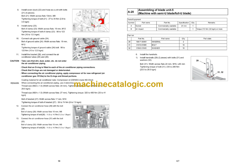
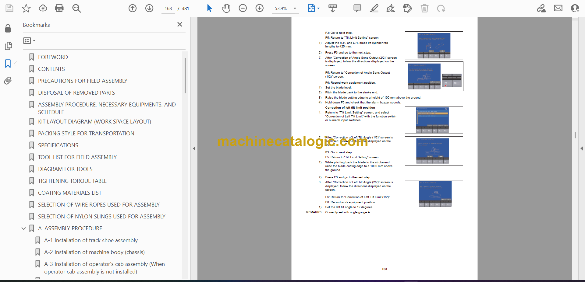
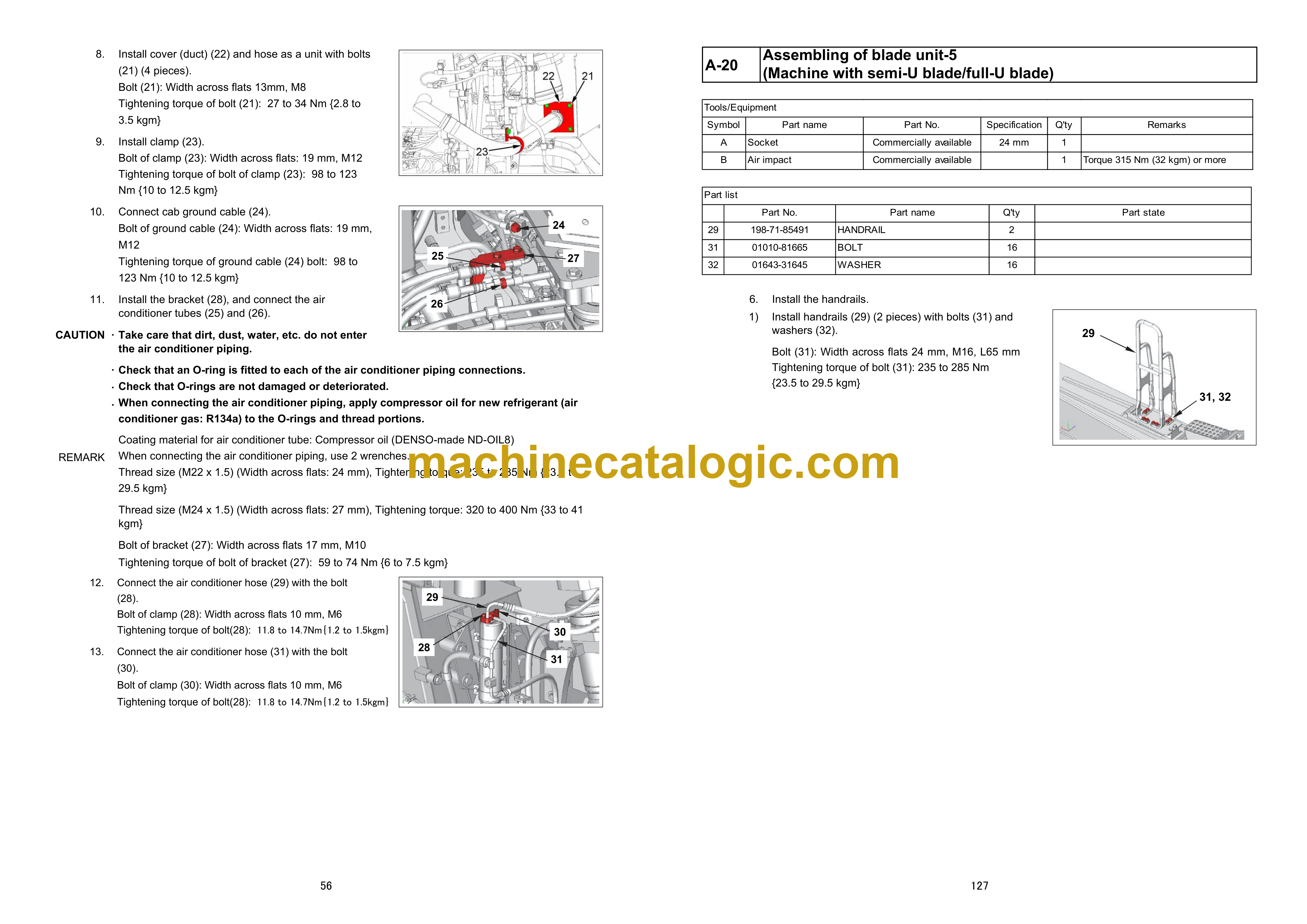
A-20 Assembling of blade unit-5 (Machine with semi-U blade/full-U blade)
A-20 Assembling of blade unit-1 (Machine with superdozer blade)
A-20 Assembling of blade unit-2 (Machine with superdozer blade)
A-20 Assembling of blade unit-3 (Machine with superdozer blade)
A-20 Assembling of blade unit-4 (Machine with superdozer blade)
A-20 Assembling of blade unit-5 (Machine with superdozer blade)
A-21 Installation of blade assembly (Machine with semi-U blade/full-U blade)
A-21 Installation of blade assembly (Machine with superdozer blade)
A-22 Installation of KOMTRAX antenna
A-23 Installation of ROPS
A-24 Installation of engine air intake port hood (When engine air intake port hood is not installed)
A-25 Installation of pre-cleaner (optional) (When pre-cleaner is not installed)
A-26 Installation of engine exhaust pipe (When engine exhaust pipe is not installed)
A-27 Installation of headlamp (When headlamp is not installed)
A-28 Installation of giant ripper shank
A-29 Adjustment of blade tilt control angle (Machine with semi-U blade/full-U blade)
A-30 Adjustment of blade tilt control angle (Machine with superdozer)
A-31 Blade pitch current value correction (Machine with superdozer)
A-32 Installation of platform-1
A-32 Installation of platform-2
A-32 Installation of platform-3
A-32 Installation of platform-4
A-33 Greasing each part
A-34 Bleeding air from hydraulic cylinder
A-35 Bleeding air from work equipment pump and fan pump
A-36 Installation of quick charge piping (optional)
A-37 Installation of ladder – 1 (For machine with ladder)
A-37 Installation of ladder – 2 (For machine with ladder)
A-37 Installation of ladder – 3 (For machine with ladder)
A-37 Installation of ladder – 4 (For machine with ladder)
A-37 Installation of ladder – 5 (For machine with ladder)
A-38 Installation of ladder – 1 (For machine with retrofitting ladder)
A-38 Installation of ladder – 2 (For machine with retrofitting ladder)
A-38 Installation of ladder – 3 (For machine with retrofitting ladder)
A-38 Installation of ladder – 4 (For machine with retrofitting ladder)
A-38 Installation of ladder – 5 (For machine with retrofitting ladder)
A-38 Installation of ladder – 6 (For machine with retrofitting ladder)
A-39 Installation of access light and additional work lamp (optional)
A-40 Installation of stroke sensing blade lift cylinder (For ICT specification)
A-41 Installation of stroke sensor harness (When installing the ICT local modification kit)
A-42 Installation of IMU sensor (When installing the ICT local modification kit)
A-43 Installation of ICT harness (When installing the ICT local modification kit)
A-44 Installation of AUX BOX (For ICT specification)
A-45 Installation of navigation controller (When installing the ICT local modification kit)
A-46 Installation of control box (When installing the ICT local modification kit)
A-47 Installation of offset switch (When installing the ICT local modification kit)
A-48 Installation of blade lift cylinder anti-drop bracket (Optional)
M. CHECK AND MAINTENANCE PROCEDURES AFTER COMPLETION OF ASSEMBLY
M-1 Checking machine monitor – 1
M-1 Checking machine monitor – 2
M-1 Checking machine monitor – 3
M-1 Checking machine monitor – 4
M-1 Checking machine monitor – 5
M-2 Adjustment menu
M-3 Change of return filter (Standard filter → Flushing filter)
M-4 Flushing hydraulic circuit and bleeding air from cylinder – 1
M-5 Change of return filter (Flushing filter → Standard filter)
M-6 Bleeding air from cylinder – 2
M-7 How to start operation of KOMTRAX terminal and how to initializeKOMTRAX Plus controller
M-8 No-injection cranking of engine
M-9 Calibration of cutting edge
APPENDIX 1 INSTALLATION OF SPILL GUARDS
APPENDIX 2 FIELD ASSEMBLY INSPECTION REPORT


