These Komatsu D61EX-24, D61EX-24E0, D61PX-24 crawler dozers are mid-size production machines used for grading, pushing, and site prep on construction and earthmoving jobs. The people who usually reach for a Shop Manual are dealership techs, independent mechanics, and fleet shops trying to do real repairs, not just daily checks. They’re usually chasing a fault code, planning a teardown, or double-checking an adjustment before they button a machine back up.
What this manual helps you do
- Trace hydraulic and electrical faults on the D61EX-24 series using the system layouts and step-by-step diagnostic flows these manuals usually provide.
- Check disassembly and assembly sequences for major components like the diesel engine, powertrain, final drives, and undercarriage so you don’t miss hidden fasteners or seals.
- Follow adjustment procedures for items like linkages, brakes, steering, and blade controls, with the “why” behind the steps usually explained in notes and cautions.
- Diagnose electronic control issues by following typical Komatsu troubleshooting trees for sensors, controllers, and wiring on these specific dozer variants.
- Handle scheduled workshop-level service tasks correctly, including inspections that most students forget, like rechecking movement after adjustment or re-bleeding circuits.
Who this is for
This Shop Manual is aimed at field techs, shop mechanics, and serious trainees who are actually turning wrenches on these exact Komatsu D61EX-24, D61EX-24E0, and D61PX-24 crawler dozers. If you’re just operating the machine or only need service intervals and basic greasing points, you’d want the Operation & Maintenance manual instead.
FAQ
Q: Is this a PDF I can search and print?
A: Yes, it’s typically provided as a searchable PDF that you can view on a laptop or tablet and print specific pages for the job.
Q: Is it deep enough for full rebuilds, or just basic service?
A: This kind of Komatsu Shop Manual usually covers workshop-level repair, from diagnostics through major component disassembly, inspection, and reassembly.
Q: How do I know it matches my exact machine?
A: Check your dozer’s model designation and the book number SEN06855-12; if your plate shows D61EX-24, D61EX-24E0, or D61PX-24 and your serial range matches what your dealer confirms for this book, you’re in the right place.
Bottom line: If you’re repairing or training on these specific D61EX-24 series dozers in a shop or field setting, this is the manual you want; if you just need basic operation guidance, keep looking for the O&M book instead.
📘 Show Index
Table of Contents:
- 00 Index and Foreword
- Index
- Foreword, Safety, Basic Information
- How to Read the Shop Manual
- Safety Notice for Operation
- Precautions to Prevent Fire
- Procedures If Fire Occurs
- Precautions for Disposing of Waste Materials
- Engine Technology to Conform Exhaust Gas Emission
- Precautions for DEF
- General Character and Precautions for Handling
- Precautions for Adding
- Precautions for Storage
- Precautions for Fire Hazard and Leakage
- Other Precautions
- Store DEF
- Precautions When You Handle Hydraulic Equipment
- Precautions When You Disconnect and Connect Pipings
- Precautions When You Handle Electrical Equipment
- Precautions When You Handle Fuel System Equipment
- Precautions When You Handle Intake System Equipment
- Practical Use of KOMTRAX
- Disconnect and Connect Push-Pull Type Coupler
- How to Disconnect and Connect Type 1 Push-Pull Type Coupler
- How to Disconnect and Connect Type 2 Push-Pull Type Coupler
- How to Disconnect and Connect Type 3 Push-Pull Type Coupler
- Precautions for Disconnection and Connection of Connectors
- How to Disconnect and Connect Deutsch Connector
- How to Disconnect and Connect Slide Lock Type Connector
- How to Disconnect and Connect Connector with Lock to Pull
- How to Disconnect and Connect Connector with Lock to Push
- How to Disconnect and Connect Connector with Housing to Rotate
- How to Read the Codes for Electric Cable
- Explanation of Terms for Maintenance Standard
- Standard Tightening Torque Table
- Conversion Table
- Abbreviation List
- 01 Specifications
- Table of Contents
- Specifications
- Specification Drawing
- Specification Drawing: D61EX-24
- Specification Drawing: D61EX-24E0
- Specification Drawing: D61PX-24
- Specification Drawing: D61PX-24E0
- Specifications
- Specifications: D61EX-24
- Specifications: D61EX-24E0
- Specifications: D61PX-24
- Specifications: D61PX-24E0
- Weight Table
- Weight Table: D61EX-24
- Weight Table: D61EX-24E0
- Weight Table: D61PX-24
- Weight Table: D61PX-24E0
- Fuel, Coolant, Lubricants (For North America)
- How to Use Fuel, Coolant and Lubricants by Ambient Temperature
- Fuel, Coolant, Lubricants (For European Union)
- How to Use Fuel, Coolant and Lubricants by Ambient Temperature
- 10 Structure and Function
- Table of Contents
- Urea SCR System
- Layout Drawing of Urea SCR System
- Urea SCR System Diagram
- Function of Urea SCR System
- Function of DEF System
- Inducement Strategy
- Component Parts of Urea SCR System
- DEF Mixing Tube
- SCR Assembly
- DEF Tank
- DEF Pump
- DEF Injector
- DEF Hose
- DEF Tank Heating Valve
- Boot-up System
- Layout Drawing of Boot-up System (Machine Without DEF purge relay)
- Layout Drawing of Boot-up System (Machine with DEF purge relay)
- System Operating Lamp System
- System Diagram of System Operating Lamp System (Machine Without DEF purge relay)
- System Diagram of System Operating Lamp System (Machine with DEF purge relay)
- Function of Operation Lamp System (Machine Without DEF purge relay)
- Function of Operation Lamp System (Machine with DEF purge relay)
- Battery Disconnect Switch
- Layout Drawing of Battery Disconnect Switch
- Function of Battery Disconnect Switch
- Engine System
- Layout Drawing of Engine System
- Engine Control System
- Layout Drawing of Engine Control System
- System Diagram of Engine Control
- Function of Engine Control System
- Automatic Idle Stop System
- System Diagram of Automatic Idle Stop System
- Function of Automatic Idle Stop System
- Component Parts of Engine System
- Damper
- VGT
- EGR System
- EGR Valve
- EGR Cooler
- KCCV System
- KCCV Ventilator
- KDPF
- Cooling System
- Layout Drawing of Cooling System
- Specifications of Cooling System
- Cooling Fan Control System
- System Diagram of Cooling Fan Control System
- Function of Cooling Fan Control System
- Component Parts of Cooling System
- Cooling Fan Motor
- Hydraulic Oil Cooler Bypass and HST Charge Safety Valve
- Hydraulic Oil Cooler Bypass Valve
- HST Charge Safety Valve
- Control System
- Layout Drawing of Control System
- Machine Monitor System
- System Diagram of Machine Monitor System
- Function of Machine Monitor System
- KOMTRAX System
- System Diagram of KOMTRAX System
- Function of KOMTRAX System
- Component Parts of Control System
- Machine Monitor
- Gateway Function Controller
- Communication Terminal
- HST Controller
- Engine Controller
- Decelerator and Brake Potentiometer
- Hydraulic System
- Layout Drawing of Hydraulic System
- CLSS
- Structure of CLSS
- Function of CLSS
- Component Parts of Hydraulic System
- Hydraulic Tank
- Work Equipment and Cooling Fan Pump
- LS Valve
- PC Valve
- Control Valve
- Power Train System
- Layout Drawing of HST System (Serial Number: 45001 to 46682)
- Layout Drawing of HST System (Serial Number: 46683 to 46684)
- Layout Drawing of HST System (Serial Number: 46685 and up)
- Operation of HST System
- Steering and Brake Control System
- Layout Drawing of Steering and Brake Control System
- Function of Steering and Brake Control System
- HST Control System
- System Diagram of HST Control System
- Gear Shift Control Function
- Engine Low Speed Matching Control Function
- HST Pump and Motor Sequence Control Function
- Deceleration and Brake Control Function
- Gear Shift Control Function by Load
- Turn Control Function
- Straight Travel Correction Control Function
- Parking Brake Control System
- System Diagram of Parking Brake Control System
- Function of Parking Brake Control System
- Operation of Parking Brake Control System
- Component Parts of Power Train System
- HST Pump
- HST Charge Pump
- HST Motor
- Final Drive
- Electric Steering Lever
- Work Equipment System
- Work Equipment Control
- Layout Drawing of Work Equipment Control
- Function of Work Equipment Control
- Layout Drawing of Front Work Equipment
- Layout Drawing of Fixed Multi-Shank Ripper
- Component Parts of Work Equipment System
- Ripper PPC Valve
- 5-Spool EPC and Solenoid Valve
- Pilot Circuit Accumulator
- Angle Control EPC Valve
- Quick Drop Valve
- Piston Valve
- Electric Blade Control Lever
- Undercarriage and Frame
- Main Frame
- Suspension
- Structure of Suspension
- Specifications of Suspension
- Function of Suspension
- Track Frame and Idler Cushion
- Structure of Track Frame and Idler Cushion
- Function of Track Frame and Idler Cushion
- Work Equipment
- Structure of Front Work Equipment
- Structure of Fixed Multi-Shank Ripper
- CAB Related Parts
- ROPS CAB
- Structure of ROPS CAB
- Function of ROPS CAB
- CAB Mount
- Structure of CAB Mount
- Function of CAB Mount
- 20 Standard Value Table
- Table of Contents
- Standard Value Table for Engine
- Standard Value Table for Engine: D61EX-24
- Standard Value Table for Engine: D61EX-24E0
- Standard Value Table for Engine: D61PX-24
- Standard Value Table for Engine: D61PX-24E0
- Standard Value Table for Machine
- Standard Value Table for Machine: D61EX-24
- Standard Value Table for Machine: D61EX-24E0
- Standard Value Table for Machine: D61PX-24
- Standard Value Table for Machine: D61PX-24E0
- Machine Posture and Procedures to Measure Performance
- 30 Testing and Adjusting
- Table of Contents
- Precautions Before Work
- Related Information on Testing and Adjusting
- Differences In Machine Monitor Symbols
- Tools for Testing and Adjusting
- Sketch of Tools for Testing and Adjusting
- Engine and Cooling System
- Examine Engine Speed
- How to Examine Engine Speed
- Examine Boost Pressure
- How to Examine Boost Pressure
- Examine Exhaust Gas Color
- How to Examine Exhaust Gas Color with the Handy Smoke Checker
- How to Examine Exhaust Gas Color with Smoke Meter
- Examine Mass Air Flow and Temperature Sensor
- How to Examine Mass Air Flow and Temperature Sensor
- Examine and Adjust Valve Clearance
- How to Examine Valve Clearance
- How to Adjust Valve Clearance
- Examine Compression Pressure
- How to Examine Compression Pressure
- Examine Blowby Pressure
- How to Examine Blowby Pressure
- Examine Engine Oil Pressure
- How to Examine Engine Oil Pressure
- Examine EGR Valve and VGT Oil Pressure
- How to Examine EGR Valve and VGT Oil Pressure
- Examine Fuel Pressure
- How to Examine Fuel Pressure
- Examine Fuel Discharge, Return and Leakage
- How to Examine Fuel Discharge, Return, and Leakage
- Bleed Air from Fuel System
- How to Bleed Air from Fuel System
- Examine Fuel Circuit for Leakage
- How to Examine Fuel System for Leakage
- Handle Cylinder Cut-out Mode Operation
- Handle No-Injection Cranking Operation
- Examine KDPF, SCR and Muffler Stack for Looseness and Damage
- How to Examine KDPF, SCR and Muffler Stack for Looseness and Damage
- Examine Installed Condition of Cylinder Heads and Manifolds
- How to Examine Installed Condition of Cylinder Heads and Manifolds
- Examine Engine Piping for Damage and Looseness
- How to Examine Engine Piping for Damage and Looseness
- Examine Alternator Belt
- How to Examine Alternator Belt
- Examine Automatic Tensioner
- How to Examine Automatic Tensioner
- Correct Soot Accumulation Correction Value by Ash Influence
- How to Correct Soot Accumulation Correction Value by Ash Influence
- Examine SCR Related Functions
- Examine DEF Pump Raised Pressure
- Examine Injection Volume from DEF Injector
- Examine DEF Line Heater Relay 1
- Examine DEF Line Heater Relay 2
- Examine DEF Pump Heater Relay
- Examine DEF Tank Heater Valve
- Examine SCR Denitration Efficiency
- Clean DEF Tank
- Clean DEF Tank Mounting Part
- How to Clean DEF Tank Mounting Part
- Clean DEF Pump
- Power Train
- Examine and Adjust HST Oil Pressure
- How to Examine HST Oil Pressure
- How to Adjust HST Oil Pressure
- Bleed Air from HST Pump
- How to Bleed Air from HST Pump
- How to Bleed Air from Servo Valve of HST Pump
- Examine Outlet Pressure of Solenoid Valve
- How to Examine Outlet Pressure of Solenoid Valve
- Examine Travel Deviation
- How to Examine Travel Deviation
- Examine Brake Performance Simply
- How to Examine Brake Performance Simply
- Examine and Adjust Deceleration/Brake Pedal
- How to Examine Deceleration/Brake Pedal
- How to Adjust Deceleration/Brake Pedal
- Adjust Parking Brake Lever
- How to Adjust Parking Brake Lever
- Move Machine When It Cannot Travel
- How to Move Machine with Hydraulic Type Parking Brake Release System
- How to Move Machine After You Remove Final Drive Shaft
- Undercarriage and Frame
- Examine and Adjust Idler Clearance
- How to Examine and Adjust Idler Clearance
- Examine Sprocket Wear
- How to Examine Sprocket Wear
- Examine and Adjust Track Tension
- How to Examine Track Tension
- How to Adjust Track Tension
- Hydraulic System
- Release Remained Pressure in Hydraulic Circuit
- How to Release Remained Pressure from Hydraulic Circuit
- Examine and Adjust Work Equipment Circuit Oil Pressure
- How to Examine Work Equipment Circuit Oil Pressure
- How to Adjust Work Equipment Circuit Oil Pressure
- Examine and Adjust Oil Pressure in Control Circuit
- How to Examine Oil Pressure in Control Circuit
- How to Adjust Oil Pressure in Control Circuit
- Examine Outlet Pressure of EPC Solenoid Valve
- How to Examine Outlet Pressure of EPC Solenoid Valve
- Bleed Air from Work Equipment, Cooling Fan Pump, and Charge Pump
- How to Bleed Air from Work Equipment, Cooling Fan Pump, and Charge Pump
- Examine Cooling Fan Speed
- How to Examine Cooling Fan Speed
- Examine Cooling Fan Circuit Oil Pressure
- How to Examine Cooling Fan Circuit Oil Pressure
- Examine Parts Which Cause Hydraulic Drift of Work Equipment
- How to Examine Parts Which Cause Hydraulic Drift of Blade Lift Cylinder
- How to Examine the Parts Which Cause Hydraulic Drift of Blade Tilt Cylinder
- How to Examine the Parts Which Cause Hydraulic Drift of Ripper Lift Cylinder
- Examine Oil Leakage from Work Equipment Cylinder
- How to Examine Internal Oil Leakage of Work Equipment Cylinder
- Bleed Air from Work Equipment Cylinders
- How to Bleed Air from Work Equipment Cylinder
- Work Equipment
- Adjust Work Equipment Lock Lever
- How to Adjust Work Equipment Lock Lever
- Examine and Adjust Play of Blade Electric Lever
- How to Examine Play of Blade Electric Lever
- How to Adjust Play of Blade Electric Lever
- How to Replace Universal Joint
- Electrical System
- Set and Operate Machine Monitor
- Operator Mode
- Function to Show Technician Identification Status Screen
- Function to Show Operator Identification Input Screen
- Examine Function by LCD (Liquid Crystal Display)
- Examine Function of Service Meter
- How to Set Usage Limitation and Change Maintenance Password
- Service Mode
- How to Operate Service Mode
- How to See Pre-defined Monitoring Information
- How to Examine Self-Define Monitor Information
- Abnormality Record Menu
- How to See Maintenance Record
- Maintenance Mode Setting
- How to Set Phone Number Entry
- Default Menu
- Diagnostic Tests Menu
- Adjustment Menu
- No-Injection Cranking Operation
- KOMTRAX Settings Menu
- How to Show Service Message
- How to Start Up KOMTRAX System
- How to Stop Use of KOMTRAX System
- Adjust After Replacement of HST Controller
- How to Adjust After Replacement of HST Controller
- Adjust After Replacement of Electric and Hydraulic Equipment
- Adjust Rearview Camera Angle
- How to Adjust Rearview Camera Angle
- Set Region of Bluetooth(R) Compatible Radio
- How to Set Region of Bluetooth(R) Compatible Radio
- Handle Voltage Circuit of Engine Controller
- Handle Battery Disconnect Switch
- Examine Diodes
- How to Examine Diodes by Digital Tester
- How to Examine Diodes by Analog Tester
- Pm Clinic
- Pm Clinic Service
- Pm Clinic Check Sheet: D61EX-24
- Pm Clinic Check Sheet: D61EX-24E0
- Pm Clinic Check Sheet: D61PX-24
- Pm Clinic Check Sheet: D61PX-24E0
- Pm Clinic Check Sheet for Undercarriage: D61EX-24
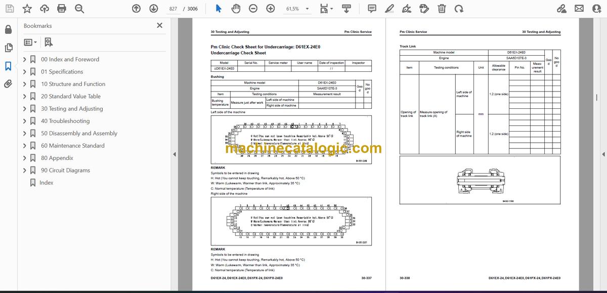
- Pm Clinic Check Sheet for Undercarriage: D61EX-24E0
- Pm Clinic Check Sheet for Undercarriage: D61PX-24
- Pm Clinic Check Sheet for Undercarriage: D61PX-24E0
- 40 Troubleshooting
- Table of Contents
- Precautions Before Work
- Abbreviation List
- Related Information to Troubleshooting
- General Troubleshooting Points
- Troubleshooting Points for Urea SCR System
- Sequence of Events in Troubleshooting
- Checks Before Troubleshooting
- Inspection Procedure Before Troubleshooting
- Test in Accordance with Testing Procedure
- Examine Fuel Level and Type
- Examine for Impure Ingredient in Fuel
- Examine DEF Level and Type
- Examine Fuel Prefilter
- Examine Fuel Main Filter
- Examine Water Pump for Leakage
- Examine Engine Oil Level (Oil Quantity in Oil Pan) and Type
- Examine Coolant Level (Reservoir Tank)
- Examine Air Cleaner Clogging
- Clean Outer Element
- Replace Element
- Examine Hydraulic Oil Level
- Examine Hydraulic Oil Strainer
- Examine Hydraulic Oil Filter
- Examine Oil Level in Final Drive Case
- Bleed Air from Fuel System
- Bleed Air from Hydraulic System
- How to Examine Electric Equipment
- Preparation for Troubleshooting of Electrical System
- Procedure for Troubleshooting
- Information Shown in Troubleshooting Table
- How to Diagnose Wiring Harness for Open Circuit of Pressure Sensor System
- Connector List and Layout
- Connector Contact Connection Table
- T-Branch Box and T-Branch Adapter Table
- Fuse Location Table
- Precautions When You Clean and Replace KDPF (KCSF and KDOC)
- Prepare Short Circuit Electrical Connector (For Failure Codes [CA1883] and [CA3135])
- Failure Code Table
- Troubleshooting by Failure Code (Display of Code)
- Failure Code [6091NX]
- Failure Code [989L00]
- Failure Code [989M00]
- Failure Code [989N00]
- Failure Code [A1U0N3]
- Failure Code [A1U0N4]
- Failure Code [A900FR]
- Failure Code [A900N6]
- Failure Code [A900NY]
- Failure Code [AA10NX]
- Failure Code [AB00KE]
- Failure Code [AQ10N3]
- Failure Code [AS00N3]
- Failure Code [AS00R2]
- Failure Code [AS00R3]
- Failure Code [AS00R4]
- Failure Code [AS00R5]
- Failure Code [AS00R6]
- Failure Code [AS00ZK]
- Failure Code [AS10KM]
- Failure Code [AS10NR]
- Failure Code [AS10NT]
- Failure Code [B@BAZG]
- Failure Code [B@BCNS]
- Failure Code [B@BCQA]
- Failure Code [B@BCZK]
- Failure Code [B@CRNS]
- Failure Code [B@CRZG]
- Failure Code [CA115]
- Failure Code [CA122]
- Failure Code [CA123]
- Failure Code [CA131]
- Failure Code [CA132]
- Failure Code [CA144]
- Failure Code [CA145]
- Failure Code [CA153]
- Failure Code [CA154]
- Failure Code [CA187]
- Failure Code [CA221]
- Failure Code [CA222]
- Failure Code [CA227]
- Failure Code [CA234]
- Failure Code [CA238]
- Failure Code [CA239]
- Failure Code [CA249]
- Failure Code [CA256]
- Failure Code [CA271]
- Failure Code [CA272]
- Failure Code [CA322]
- Failure Code [CA323]
- Failure Code [CA324]
- Failure Code [CA325]
- Failure Code [CA331]
- Failure Code [CA332]
- Failure Code [CA343]
- Failure Code [CA351]
- Failure Code [CA352]
- Failure Code [CA356]
- Failure Code [CA357]
- Failure Code [CA386]
- Failure Code [CA428]
- Failure Code [CA429]
- Failure Code [CA435]
- Failure Code [CA441]
- Failure Code [CA442]
- Failure Code [CA449]
- Failure Code [CA451]
- Failure Code [CA452]
- Failure Code [CA488]
- Failure Code [CA515]
- Failure Code [CA516]
- Failure Code [CA553]
- Failure Code [CA555]
- Failure Code [CA556]
- Failure Code [CA559]
- Failure Code [CA595]
- Failure Code [CA687]
- Failure Code [CA689]
- Failure Code [CA691]
- Failure Code [CA692]
- Failure Code [CA697]
- Failure Code [CA698]
- Failure Code [CA731]
- Failure Code [CA778]
- Failure Code [CA1117]
- Failure Code [CA1664]
- Failure Code [CA1669]
- Failure Code [CA1673]
- Failure Code [CA1677]
- Failure Code [CA1678]
- Failure Code [CA1682]
- Failure Code [CA1683]
- Failure Code [CA1684]
- Failure Code [CA1686]
- Failure Code [CA1691]
- Failure Code [CA1694]
- Failure Code [CA1695]
- Failure Code [CA1696]
- Failure Code [CA1712]
- Failure Code [CA1713]
- Failure Code [CA1714]
- Failure Code [CA1715]
- Failure Code [CA1776]
- Failure Code [CA1777]
- Failure Code [CA1843]
- Failure Code [CA1844]
- Failure Code [CA1879]
- Failure Code [CA1881]
- Failure Code [CA1883] (D61EX-24, D61PX-24, D61EXI-24, D61PXI-24)
- Failure Code [CA1883] (D61EX-24E0, D61PX-24E0, D61EXI-24E0, D61PXI-24E0)
- Failure Code [CA1885]
- Failure Code [CA1887]
- Failure Code [CA1921]
- Failure Code [CA1922]
- Failure Code [CA1942]
- Failure Code [CA1993] (D61EX-24, D61PX-24, D61EXI-24, D61PXI-24)
- Failure Code [CA1993] (D61EX-24E0, D61PX-24E0, D61EXI-24E0, D61PXI-24E0)
- Failure Code [CA2185]
- Failure Code [CA2186]
- Failure Code [CA2249]
- Failure Code [CA2271]
- Failure Code [CA2272]
- Failure Code [CA2288]
- Failure Code [CA2311]
- Failure Code [CA2349]
- Failure Code [CA2353]
- Failure Code [CA2357]
- Failure Code [CA2381]
- Failure Code [CA2382]
- Failure Code [CA2383]
- Failure Code [CA2386]
- Failure Code [CA2387]
- Troubleshooting Flowchart
- Failure Code [CA2555]
- Failure Code [CA2556]
- Failure Code [CA2637]
- Failure Code [CA2639]
- Failure Code [CA2771]
- Failure Code [CA2777]
- Failure Code [CA2976]
- Failure Code [CA3133]
- Failure Code [CA3134]
- Failure Code [CA3135]
- Failure Code [CA3142]
- Failure Code [CA3143]
- Failure Code [CA3144]
- Failure Code [CA3146]
- Failure Code [CA3147]
- Failure Code [CA3148]
- Failure Code [CA3151]
- Failure Code [CA3165]
- Failure Code [CA3229]
- Failure Code [CA3231]
- Failure Code [CA3232]
- Failure Code [CA3235]
- Failure Code [CA3239]
- Failure Code [CA3241]
- Failure Code [CA3242]
- Failure Code [CA3251]
- Failure Code [CA3253]
- Failure Code [CA3254]
- Failure Code [CA3255]
- Failure Code [CA3256]
- Failure Code [CA3311]
- Failure Code [CA3312]
- Failure Code [CA3313]
- Failure Code [CA3314]
- Failure Code [CA3315]
- Failure Code [CA3316]
- Failure Code [CA3317]
- Failure Code [CA3318]
- Failure Code [CA3319]
- Failure Code [CA3321]
- Failure Code [CA3322]
- Failure Code [CA3419]
- Failure Code [CA3421]
- Failure Code [CA3497]
- Failure Code [CA3498]
- Failure Code [CA3543]
- Failure Code [CA3545]
- Failure Code [CA3547]
- Failure Code [CA3558]
- Failure Code [CA3559]
- Failure Code [CA3562]
- Failure Code [CA3563]
- Failure Code [CA3567]
- Failure Code [CA3568]
- Failure Code [CA3571]
- Failure Code [CA3572]
- Failure Code [CA3574]
- Failure Code [CA3575]
- Failure Code [CA3577]
- Failure Code [CA3578]
- Failure Code [CA3582]
- Failure Code [CA3583]
- Failure Code [CA3596]
- Failure Code [CA3649]
- Failure Code [CA3681]
- Failure Code [CA3682]
- Failure Code [CA3713]
- Failure Code [CA3717]
- Failure Code [CA3718]
- Failure Code [CA3725]
- Failure Code [CA3741]
- Failure Code [CA3748]
- Failure Code [CA3751]
- Failure Code [CA3755]
- Failure Code [CA3866]
- Failure Code [CA3867]
- Failure Code [CA3868]
- Failure Code [CA3899]
- Failure Code [CA3911]
- Failure Code [CA3912]
- Failure Code [CA3932]
- Failure Code [CA3933]
- Failure Code [CA3934]
- Failure Code [CA3935]
- Failure Code [CA3936]
- Failure Code [CA4151]
- Failure Code [CA4152]
- Failure Code [CA4155]
- Failure Code [CA4156]
- Failure Code [CA4157]
- Failure Code [CA4158]
- Failure Code [CA4159]
- Failure Code [CA4161]
- Failure Code [CA4162]
- Failure Code [CA4163]
- Failure Code [CA4164]
- Failure Code [CA4165]
- Failure Code [CA4166]
- Failure Code [CA4168]
- Failure Code [CA4169]
- Failure Code [CA4171]
- Failure Code [CA4249]
- Failure Code [CA4251]
- Failure Code [CA4259]
- Failure Code [CA4261]
- Failure Code [CA4277]
- Failure Code [CA4281]
- Failure Code [CA4459]
- Failure Code [CA4461]
- Failure Code [CA4658]
- Failure Code [CA4731]
- Failure Code [CA4732]
- Failure Code [CA4739]
- Failure Code [CA4768]
- Failure Code [CA4769]
- Failure Code [CA4842]
- Failure Code [CA4952] (Machine Without DEF purge relay)
- Failure Code [CA4952] (Machine with DEF purge relay)
- Failure Code [CA5115]
- Failure Code [CA5383]
- Failure Code [D130KA]
- Failure Code [D130KB]
- Failure Code [D130KY]
- Failure Code [D19JKZ]
- Failure Code [D19UKA]
- Failure Code [D19UKB]
- Failure Code [D19UMC]
- Failure Code [D811MC]
- Failure Code [D862KA]
- Failure Code [D8ALKA]
- Failure Code [D8ALKB]
- Failure Code [D8AQKR]
- Failure Code [D8G1KT]
- Failure Code [D8G6KT]
- Failure Code [DAF0MB]
- Failure Code [DAF0MC]
- Failure Code [DAF8KB]
- Failure Code [DAF9KQ]
- Failure Code [DAFGMC]
- Failure Code [DAFLKA]
- Failure Code [DAFLKB]
- Failure Code [DAFQKR]
- Failure Code [DAJ000]
- Failure Code [DAJ0KQ]
- Failure Code [DAJ0KT]
- Failure Code [DAJ0MC]
- Failure Code [DAJ1KK]
- Failure Code [DAJ2KK]
- Failure Code [DAJ2KT]
- Failure Code [DAJ5KK]
- Failure Code [DAJ6KK]
- Failure Code [DAJLKA]
- Failure Code [DAJLKB]
- Failure Code [DAJPMA]
- Failure Code [DAJQKR]
- Failure Code [DAJRKR]
- Failure Code [DB2QKR]
- Failure Code [DB2RKR]
- Failure Code [DD12KA]
- Failure Code [DD12KB]
- Failure Code [DD13KA]
- Failure Code [DD13KB]
- Failure Code [DD14KA]
- Failure Code [DD14KB]
- Failure Code [DDKAKA]
- Failure Code [DDKAKB]
- Failure Code [DDKFL4]
- Failure Code [DDKGL4]
- Failure Code [DDKHKA]
- Failure Code [DDKHKB]
- Failure Code [DDNLKA]
- Failure Code [DDNLKB]
- Failure Code [DDP6KA]
- Failure Code [DDP6KB]
- Failure Code [DDP6MA]
- Failure Code [DDU1FS]
- Failure Code [DDU1KA]
- Failure Code [DDU1KY]
- Failure Code [DFA4KX]
- Failure Code [DFA4KZ]
- Failure Code [DFA4L8]
- Failure Code [DFA5KA]
- Failure Code [DFA5KB]
- Failure Code [DFA6KA]
- Failure Code [DFA6KB]
- Failure Code [DFA7KX]
- Failure Code [DFA7KZ]
- Failure Code [DFA7L8]
- Failure Code [DFA8KA]
- Failure Code [DFA8KB]
- Failure Code [DFA9KA]
- Failure Code [DFA9KB]
- Failure Code [DGS1KA]
- Failure Code [DGS1KX]
- Failure Code [DH21KA]
- Failure Code [DH21KB]
- Failure Code [DHA4KA]
- Failure Code [DHAAMA]
- Failure Code [DHACMA]
- Failure Code [DHH7KA]
- Failure Code [DHH7KB]
- Failure Code [DHH8KA]
- Failure Code [DHH8KB]
- Failure Code [DHH9KA]
- Failure Code [DHH9KB]
- Failure Code [DHHAKA]
- Failure Code [DHHAKB]
- Failure Code [DHRUKA]
- Failure Code [DHRUKB]
- Failure Code [DHRVKA]
- Failure Code [DHRVKB]
- Failure Code [DK30KA]
- Failure Code [DK30KB]
- Failure Code [DK30KX]
- Failure Code [DK30KZ]
- Failure Code [DK30L8]
- Failure Code [DK31KA]
- Failure Code [DK31KB]
- Failure Code [DK40KA]
- Failure Code [DK40KB]
- Failure Code [DK55KX]
- Failure Code [DK55KZ]
- Failure Code [DK55L8]
- Failure Code [DK56KA]
- Failure Code [DK56KB]
- Failure Code [DK57KA]
- Failure Code [DK57KB]
- Failure Code [DLM0KX]
- Failure Code [DLM1KA]
- Failure Code [DLM1KB]
- Failure Code [DLM1MA]
- Failure Code [DLM2KA]
- Failure Code [DLM2KB]
- Failure Code [DLM2MA]
- Failure Code [DLM3KA]
- Failure Code [DLM3KB]
- Failure Code [DLM3MB]
- Failure Code [DN21FS]
- Failure Code [DR21KX]
- Failure Code [DR31KX]
- Failure Code [DV20KB]
- Failure Code [DW4BKA]
- Failure Code [DW4BKB]
- Failure Code [DW4BKY]
- Failure Code [DW7BKA]
- Failure Code [DW7BKB]
- Failure Code [DW7EKA]
- Failure Code [DW7EKB]
- Failure Code [DW7EKY]
- Failure Code [DWN5KA]
- Failure Code [DWN5KB]
- Failure Code [DWN5KY]
- Failure Code [DXA4KA] (Applicable Machine: 45001 to 46273)
- Failure Code [DXA4KA] (Applicable Machine: 46274 and Up)
- Failure Code [DXA4KB] (Applicable Machine: 45001 to 46273)
- Failure Code [DXA4KB] (Applicable Machine: 46274 and Up)
- Failure Code [DXA4KY] (Applicable Machine: 45001 to 46273)
- Failure Code [DXA4KY] (Applicable Machine: 46274 and Up)
- Failure Code [DXA5KA] (Applicable Machine: 45001 to 46273)
- Failure Code [DXA5KA] (Applicable Machine: 46274 and Up)
- Failure Code [DXA5KB] (Applicable Machine: 45001 to 46273)
- Failure Code [DXA5KB] (Applicable Machine: 46274 and Up)
- Failure Code [DXA5KY] (Applicable Machine: 45001 to 46273)
- Failure Code [DXA5KY] (Applicable Machine: 46274 and Up)
- Failure Code [DXA6KA] (Applicable Machine: 45001 to 46273)
- Failure Code [DXA6KA] (Applicable Machine: 46274 and Up)
- Failure Code [DXA6KB] (Applicable Machine: 45001 to 46273)
- Failure Code [DXA6KB] (Applicable Machine: 46274 and Up)
- Failure Code [DXA6KY] (Applicable Machine: 45001 to 46273)
- Failure Code [DXA6KY] (Applicable Machine: 46274 and Up)
- Failure Code [DXA7KA] (Applicable Machine: 45001 to 46273)
- Failure Code [DXA7KA] (Applicable Machine: 46274 and Up)
- Failure Code [DXA7KB] (Applicable Machine: 45001 to 46273)
- Failure Code [DXA7KB] (Applicable Machine: 46274 and Up)
- Failure Code [DXA7KY] (Applicable Machine: 45001 to 46273)
- Failure Code [DXA7KY] (Applicable Machine: 46274 and Up)
- Failure Code [DXHRKA]
- Failure Code [DXHRKB]
- Failure Code [DXHRKY]
- Failure Code [DXHSKA]
- Failure Code [DXHSKB]
- Failure Code [DXHSKY]
- Failure Code [DXHTKA]
- Failure Code [DXHTKB]
- Failure Code [DXHTKY]
- Failure Code [DXHUKA]
- Failure Code [DXHUKB]
- Failure Code [DXHUKY]
- Failure Code [DXJ4KA]
- Failure Code [DXJ4KB]
- Failure Code [DXJCKA]
- Failure Code [DXJCKB]
- Failure Code [DXJCKY]
- Failure Code [DXJDKA]
- Failure Code [DXJDKB]
- Failure Code [DXJDKY]
- Failure Code [DXK1KA]
- Failure Code [DXK1KB]
- Failure Code [DXK1KY]
- Failure Code [DXK2KA]
- Failure Code [DXK2KB]
- Failure Code [DXK2KY]
- Failure Code [F311KA]
- Failure Code [F311KB]
- Failure Code [F312KA]
- Failure Code [F312KB]
- Failure Code [F313KA]
- Failure Code [F313KB]
- Failure Code [F314KA]
- Failure Code [F314KB]
- Failure Code [F315KB]
- Failure Code [F315KY]
- Failure Code [F316KB]
- Failure Code [F316KY]
- Failure Code [F318KB]
- Failure Code [F318KY]
- Failure Code [F31AKB]
- Failure Code [F31AKY]
- Failure Code [F31BKB]
- Failure Code [F31BKY]
- Failure Code [F31CKB]
- Failure Code [F31CKY]
- Failure Code [F31DKB]
- Failure Code [F31DKY]
- Failure Code [F31EKB]
- Failure Code [F31EKY]
- Failure Code [FS10ZE]
- Troubleshooting of Electrical System (E-Mode)
- Engine Does Not Start (Engine Does Not Crank)
- Manual Preheating System Does Not Operate
- Automatic Preheating System Does Not Operate
- While Preheating is in Operation, Preheating Monitor Does Not Come On
- When Starting Switch is Turned to ON Position, Machine Monitor Shows Nothing
- When Starting Switch is Turned to ON Position (with Engine Stopped), Basic Check Monitor Comes On
- Air Cleaner Clogging Monitor Comes On in Yellow While Engine is in Operation
- Charge Level Monitor Comes On in Red While Engine is in Operation
- Engine Coolant Temperature Monitor Comes On in Red While Engine is in Operation
- Engine Oil Pressure Monitor Comes On in Red While Engine is in Operation
- HST Charge Pressure Monitor Comes On in Red While Engine Runs
- Hydraulic Oil Temperature Monitor Comes On in Red While Engine is in Operation
- HST Oil Filter Clogging Monitor Comes On in Red While Engine Runs
- Engine Coolant Temperature Gauge Does Not Show Correct Temperature
- Fuel Gauge Does Not Show Normally
- Hydraulic Oil Temperature Gauge Does Not Show Correct Temperature
- Operation Mode Does Not Change
- When You Operate Customize Switch Does Not Show Customize Screen
- When You Change Setting on Customize Screen, Setting of Machine is Not Changed
- Service Meter is Not Shown While Starting Switch is in OFF Position
- Service Mode Cannot be Selected
- Work Equipment Does Not Operate
- Foot Heater Does Not Operate
- Horn Does Not Sound
- Horn Does Not Stop
- Backup Alarm Does Not Sound
- Backup Alarm Does Not Stop Operation
- Headlamp Does Not Come On
- Rear Lamp Does Not Come On
- No Wiper Operates
- Front Wiper Does Not Operate
- Rear Wiper Does Not Operate
- Left Door Wiper Does Not Operate
- Right Door Wiper Does Not Operate
- Front Washer Does Not Operate
- Rear Washer Does Not Operate
- Left Door Washer Does Not Operate
- Right Door Washer Does Not Operate
- KOMTRAX System Does Not Operate Correctly
- Troubleshooting for Hydraulic and Mechanical Systems (H Mode)
- Information Shown in Troubleshooting Table (H-Mode)
- Failure Mode and Cause Table
- R.H. and L.H. Tracks Cannot Travel FORWARD and REVERSE (None of the Travel Systems Operate)
- R.H. or L.H. Track Cannot Travel FORWARD and REVERSE (One of R.H. or L.H. Travel Systems Cannot Operate)
- R.H. or L.H. Track Cannot Travel FORWARD or REVERSE (Only One of the Travel Systems Cannot Operate in One Direction)
- Travel Speed or Power is Low
- Speed Range Does Not Change
- Shock is Large When Machine Moves Off or Stops
- Travel Deviation is Large
- Machine Drift on a Slope is Large
- Engine Speed Drops Largely or Engine Stops
- Unusual Noise is Heard from Around HST Pump or Motor
- HST Oil Temperature (Hydraulic Oil Temperature) Increases Too High
- All Work Equipment Do Not Operate
- All Work Equipment Speed or Power is Low
- Blade Lift Speed or Power is Low
- Blade Tilt Speed or Power is Low
- Blade Angle Speed or Power is Low
- Time Lag of Blade Lift is Large
- Hydraulic Drift of Blade Lift is Large
- Hydraulic Drift of Tilted Blade is Large
- Unusual Noise is Heard from Around Work Equipment and Cooling Fan Pump or Control Valve
- Fan Speed is Abnormal (Too High or Low, or Does Not Rotate)
- Unusual Noise is Heard from Around Fan
- Final Drive Breather is Contaminated with Oil
- Troubleshooting of Engine (S-Mode)
- Information Shown in Troubleshooting Table (S-Mode)
- Engine Does Not Crank When Starting Switch is Turned to Start Position
- Engine Cranks but No Exhaust Smoke Comes Out
- Fuel is Sprayed but Engine Does Not Start (Misfiring: Engine Cranks but Does Not Start)
- Engine Startability is Unsatisfactory
- Engine Does Not Pick Up Smoothly
- Engine Stops During Operation
- Engine Does Not Rotate Smoothly
- Engine Lacks Output (or Lacks Power)
- KDPF Becomes Clogged in a Short Time
- Engine Oil Consumption is Excessive
- Engine Oil Becomes Dirty Quickly
- Fuel Consumption is Excessive
- Oil is in Coolant (or Coolant Spurts Back or Coolant Level Goes Down)
- Engine Oil Pressure Drops
- Fuel Mixes Into Engine Oil
- Water Mixes Into Engine Oil (Milky)
- Coolant Temperature Increases Too High (Overheat)
- Unusual Noise is Heard
- Vibration is Excessive
- Air Cannot be Bled from Fuel Circuit
- Active Regeneration is Done Frequently
- Active Regeneration Continues Long
- White Smoke is Exhausted During Active Regeneration
- DEF Consumption is Excessive
- There is an Unusual Smell (Irritating Odor)
- Foreign Materials Enter DEF (DEF Increases)
- 50 Disassembly and Assembly
- Table of Contents
- Precautions Before Work
- Abbreviation List
- Related Information on Disassembly and Assembly
- How to Read This Manual
- Coating Materials List
- Special Tool List
- Sketches of Special Tools
- Engine and Cooling System
- Remove and Install Supply Pump Assembly
- How to Remove Supply Pump Assembly
- How to Install Supply Pump Assembly
- Remove and Install Injector Assembly
- How to Remove Injector Assembly
- How to Install Injector Assembly
- Remove and Install Cylinder Head Assembly
- How to Remove Cylinder Head Assembly
- How to Install Cylinder Head Assembly
- Remove and Install EGR Valve Assembly
- How to Remove EGR Valve Assembly
- How to Install EGR Valve Assembly
- Remove and Install EGR Cooler Assembly
- How to Remove EGR Cooler Assembly
- How to Install EGR Cooler Assembly
- Remove and Install Starter Assembly
- How to Remove Starting Motor Assembly
- How to Install Starting Motor Assembly
- Remove and Install Alternator Belt
- How to Remove Alternator Belt
- How to Install Alternator Belt
- Remove and Install Automatic Tensioner
- How to Remove Automatic Tensioner
- How to Install Automatic Tensioner
- Remove and Install Radiator Assembly
- How to Remove Radiator Assembly
- How to Install Radiator Assembly
- Remove and Install Hydraulic Oil Cooler Assembly
- How to Remove Hydraulic Oil Cooler Assembly
- How to Install Hydraulic Oil Cooler Assembly
- Remove and Install Aftercooler Assembly
- How to Remove Aftercooler Assembly
- How to Install Aftercooler Assembly
- Remove and Install Cooling Fan Drive Assembly
- How to Remove Cooling Fan Drive Assembly
- How to Install Cooling Fan Drive Assembly
- Remove and Install Cooling Fan Motor Assembly
- How to Remove Cooling Fan Motor Assembly
- How to Install Cooling Fan Motor Assembly
- Remove and Install Engine and HST Pump Assembly
- How to Remove Engine and HST Pump Assembly
- How to Install Engine and HST Pump Assembly
- Remove and Install Engine Front Oil Seal
- How to Remove Engine Front Oil Seal
- How to Install Engine Front Oil Seal
- Remove and Install Engine Rear Oil Seal
- How to Remove Engine Rear Oil Seal
- How to Install Engine Rear Oil Seal
- Remove and Install Engine Hood Assembly
- How to Remove Engine Hood Assembly
- How to Install Engine Hood Assembly
- Remove and Install KDPF Assembly
- How to Remove KDPF Assembly
- How to Install KDPF Assembly
- Disassemble and Assemble KDPF Assembly
- How to Disassemble KDPF Assembly
- How to Assemble KDPF Assembly
- Remove and Install KDPF and SCR Assembly
- How to Remove KDPF and SCR Assembly
- How to Install KDPF and SCR Assembly
- Remove and Install Fuel Tank Assembly
- How to Remove Fuel Tank Assembly
- How to Install Fuel Tank Assembly
- Remove and Install DEF Tank Assembly
- How to Remove DEF Tank Assembly
- How to Install DEF Tank Assembly
- Remove and Install DEF Tank Sensor Flange Assembly
- How to Remove DEF Tank Sensor Flange Assembly
- How to Install DEF Tank Sensor Flange Assembly
- Remove and Install DEF Tank Sensor
- How to Remove DEF Tank Sensor
- How to Install DEF Tank Sensor
- Remove and Install DEF Tank Strainer
- How to Remove DEF Tank Strainer
- How to Install DEF Tank Strainer
- Remove and Install SCR Assembly
- How to Remove SCR Assembly
- How to Install SCR Assembly
- Remove and Install KCCV Assembly
- How to Remove KCCV Assembly
- How to Install KCCV Assembly
- Remove and Install VGT Assembly
- How to Remove VGT Assembly
- How to Install VGT Assembly
- Remove and Install DEF Mixing Tube
- How to Remove DEF Mixing Tube
- How to Install DEF Mixing Tube
- Remove and Install DEF Injector
- How to Remove DEF Injector
- How to Install DEF Injector
- Remove and Install DEF Pump
- How to Remove DEF Pump
- How to Install DEF Pump
- Remove and Install DEF Hose
- How to Remove DEF Hose
- How to Install DEF Hose
- Remove and Install Air Cleaner Assembly
- How to Remove Air Cleaner Assembly
- How to Install Air Cleaner Assembly
- Remove and Install Air Conditioner Compressor Assembly
- How to Remove Air Conditioner Compressor Assembly
- How to Install Air Conditioner Compressor Assembly
- Remove and Install Air Conditioner Condenser Assembly
- How to Remove Air Conditioner Condenser Assembly
- How to Install Air Conditioner Condenser Assembly
- Power Train
- Remove and Install Damper Assembly
- How to Remove Damper Assembly
- How to Install Damper Assembly
- Remove and Install HST Pump Assembly
- How to Remove HST Pump Assembly
- How to Install HST Pump Assembly
- Remove and Install HST Motor and Final Drive Assembly
- How to Remove HST Motor and Final Drive Assembly (Serial Number: 45001 to 46684)
- How to Remove HST Motor and Final Drive Assembly (Serial Number: 46685 and up)
- How to Install HST Motor and Final Drive Assembly (Serial Number: 45001 to 46684)
- How to Install HST Motor and Final Drive Assembly (Serial Number: 46685 and up)
- Disassemble and Assemble Final Drive Assembly (Serial Number: 45001 to 46684)
- How to Disassemble Final Drive Assembly (Serial Number: 45001 to 46684)
- How to Assemble Final Drive Assembly (Serial Number: 45001 to 46684)
- Disassemble and Assemble Final Drive Assembly (Serial Number: 46685 and up)
- How to Disassemble Final Drive Assembly (Serial Number: 46685 and up)
- How to Assemble Final Drive Assembly (Serial Number: 46685 and up)
- Undercarriage and Frame
- Remove and Install Track Frame Assembly
- How to Remove Track Frame Assembly
- How to Install Track Frame Assembly
- Remove and Install Idler Assembly
- How to Remove Idler Assembly
- How to Install Idler Assembly
- Disassemble and Assemble Idler Assembly
- How to Disassemble Idler Assembly
- How to Assemble Idler Assembly
- Remove and Install Recoil Spring Assembly
- How to Remove Recoil Spring Assembly
- How to Install Recoil Spring Assembly
- Disassemble and Assemble Recoil Spring Assembly
- How to Disassemble Recoil Spring Assembly
- How to Assemble Recoil Spring Assembly
- Remove and Install Track Roller Assembly
- How to Remove Track Roller Assembly
- How to Install Track Roller Assembly
- Disassemble and Assemble Track Roller Assembly
- How to Disassemble Track Roller Assembly
- How to Assemble Track Roller Assembly
- Remove and Install Carrier Roller Assembly
- How to Remove Carrier Roller Assembly
- How to Install Carrier Roller Assembly
- Disassemble and Assemble Carrier Roller Assembly
- How to Disassemble Carrier Roller Assembly
- How to Assemble Carrier Roller Assembly
- Remove and Install Pivot Shaft Assembly
- How to Remove Pivot Shaft Assembly
- How to Install Pivot Shaft Assembly
- Separate and Connect Track Assembly
- How to Examine Before Separation of Track Assembly
- How to Separate Track Assembly (Standard)
- How to Separate Track Assembly (When Track Frame Has Internal Defect)
- How to Install Track Assembly
- Separate and Connect PLUS Type Track Assembly
- How to Separate PLUS Type Track Assembly
- Install PLUS Type Track Assembly
- Disassemble and Assemble Track Assembly Generally
- How to Disassemble Full Track Shoes Assembly
- How to Assemble Full Track Shoes Assembly
- Disassemble and Assemble PLUS Type Track Assembly Generally
- Disassemble PLUS Type Track Assembly Generally
- How to Assemble PLUS Type Track Shoes Assembly Generally
- Disassemble and Assemble One Track Link Assembly in Field (Track Assembly)
- How to Disassemble One Track Link Assembly in Field (Track Assembly)
- How to Assemble One Track Link Assembly in Field (Track Assembly)
- Disassemble and Assemble One Track Link Assembly in Field (PLUS Type Track Assembly)
- How to Disassemble One Track Link Assembly in Field (PLUS Type Track Assembly)
- Assemble One Track Link Assembly in Field (PLUS Type Track Assembly)
- Remove and Install Equalizer Bar Assembly
- How to Remove Equalizer Bar Assembly
- How to Install Equalizer Bar Assembly
- Remove and Install Equalizer Bar Side Bushing
- How to Remove Equalizer Bar Side Bushings
- How to Install Equalizer Bar Side Bushings
- Remove and Install Segment Teeth
- How to Remove Segment Teeth
- How to Install Segment Teeth
- Hydraulic System
- Remove and Install Hydraulic Tank Assembly
- How to Remove Hydraulic Tank Assembly
- How to Install Hydraulic Tank Assembly
- Remove and Install Control Valve Assembly
- How to Remove Control Valve Assembly
- How to Install Control Valve Assembly
- Work Equipment
- Remove and Install Blade Assembly
- How to Remove Blade Assembly
- How to Install Blade Assembly
- Remove and Install Work Equipment Assembly
- How to Remove Work Equipment Assembly
- How to Install Work Equipment Assembly
- How to Disassemble and Assemble Work Equipment Cylinder Assembly
- How to Disassemble Work Equipment Cylinder Assembly
- How to Assemble Work Equipment Cylinder Assembly
- Remove and Install U-Frame Assembly
- How to Remove U-Frame Assembly
- How to Install U-Frame Assembly
- CAB Related Parts
- Remove and Install Operator Cab Assembly
- How to Remove Operator Cab Assembly
- How to Install Operator Cab Assembly
- Remove and Install Operator Cab Glass (Adhered Glass)
- How to Remove Operator Cab Glass (Adhered Glass)
- How to Install Operator Cab Glass (Adhered Glass)
- Remove and Install Air Conditioner Unit Assembly
- How to Remove Air Conditioner Unit Assembly
- How to Install Air Conditioner Unit Assembly
- Remove and Install Receiver Drier
- How to Remove Receiver Drier
- How to Install Receiver Drier
- Remove and Install Operator Seat
- How to Remove Operator Seat
- How to Install Operator Seat
- How to Remove and Install Seat Belt
- How to Remove Seat Belt
- How to Install Seat Belt
- Remove and Install Foot Heater Assembly
- How to Remove Foot Heater Assembly
- How to Install Foot Heater Assembly
- Disassemble and Assemble Foot Heater Assembly
- How to Disassemble Foot Heater Assembly
- How to Assemble Foot Heater Assembly
- Electrical System
- Remove and Install Engine Controller Assembly
- How to Remove Engine Controller Assembly
- How to Install Engine Controller Assembly
- Remove and Install HST Controller Assembly
- How to Remove HST Controller Assembly
- How to Install HST Controller Assembly
- Remove and Install Machine Monitor Assembly
- How to Remove Machine Monitor Assembly
- How to Install Machine Monitor Assembly
- Remove and Install Mass Air Flow and Temperature Sensor
- How to Remove Mass Air Flow and Temperature Sensor
- How to Install Mass Air Flow and Temperature Sensor
- Remove and Install KCCV Crankcase Pressure Sensor
- How to Remove KCCV Crankcase Pressure Sensor
- How to Install KCCV Crankcase Pressure Sensor
- Remove and Install SCR Temperature Sensor
- How to Remove SCR Temperature Sensor
- How to Install SCR Temperature Sensor
- Remove and Install Gateway Function Controller Assembly
- How to Remove Gateway Function Controller Assembly
- How to Install Gateway Function Controller Assembly
- Remove and Install Communication Terminal
- How to Remove Communication Terminal
- How to Install Communication Terminal
- 60 Maintenance Standard
- Table of Contents
- Abbreviation List
- Engine and Cooling System
- Maintenance Standard for Engine Mount
- Maintenance Standard for Damper
- Maintenance Standard for Cooling System
- Maintenance Standard for Cooling Fan Motor
- Maintenance Standard for Hydraulic Oil Cooler Bypass and HST Charge Safety Valve
- Power Train
- Maintenance Standard for HST Pump (Serial Number: 45001 to 46682)
- Maintenance Standard for EPC Valve of HST Pump
- Maintenance Standard for Tow Receiving Valve of HST Pump (Serial Number: 45001 to 46682)
- Maintenance Standard for HST Pump (Serial Number: 46683 and up)
- Maintenance Standard for EPC Valve of HST Pump
- Maintenance Standard for Tow Receiving Valve of HST Pump (Serial Number: 46683 and up)
- Maintenance Standard for HST Charge Pump
- Maintenance Standard for HST Motor (Serial Number: 45001 to 46684)
- Maintenance Standard for HST Motor (Serial Number: 46685 and up)
- Maintenance Standard for Final Drive (Serial Number: 45001 to 46684)
- Maintenance Standard for Final Drive (Serial Number: 46685 and up)
- Maintenance Standard for Sprocket for Conventional Type Track Shoes
- Maintenance Standard for Sprocket Tooth Profile Full-Scale Drawing for Conventional Type Track Shoes
- Maintenance Standard for Sprocket for PLUS Type Track Shoes
- Maintenance Standard for Sprocket Tooth Profile Full-Scale Drawing for PLUS Type Track Shoes
- Undercarriage and Frame
- Maintenance Standard for Suspension
- Maintenance Standard for Track Frame and Idler Cushion
- Maintenance Standard for Idler
- Maintenance Standard for Track Roller for Conventional Type Track Shoes (Single Flange Type)
- Maintenance Standard for Track Roller for Conventional Type Track Shoes (Double Flange Type)
- Maintenance Standard for Track Roller for PLUS Type Track Shoes (Single Flange Type)
- Maintenance Standard for Track Roller for PLUS Type Track Shoes (Double Flange Type)
- Maintenance Standard for Carrier Roller for Conventional Type Track Shoes
- Maintenance Standard for Carrier Roller for PLUS Type Track Shoes
- Maintenance Standard for Conventional Type Track Shoes
- Maintenance Standard for PLUS Type Track Shoes
- Maintenance Standard for Single Shoes
- Maintenance Standard for Swamp Shoes
- Hydraulic System
- Maintenance Standard for Hydraulic Tank
- Maintenance Standard for Work Equipment and Cooling Fan Pump
- Maintenance Standard for Servo Valve of Work Equipment and Cooling Fan Pump
- Maintenance Standard for Control Valve
- Maintenance Standard for Ripper PPC Valve
- Maintenance Standard for 5-Spool EPC and Solenoid Valve
- Maintenance Standard for EPC Valve
- Maintenance Standard for Angle Control EPC Valve
- Maintenance Standard for Quick Drop Valve
- Work Equipment
- Maintenance Standard for Front Work Equipment
- Maintenance Standard for Cutting Edge and End Bit
- Maintenance Standard for Blade Lift Cylinder
- Maintenance Standard for Blade Tilt Cylinder
- Maintenance Standard for Blade Angle Cylinder
- Maintenance Standard for Fixed Multi-Shank Ripper
- Maintenance Standard for Ripper Lift Cylinder
- CAB Related Parts
- Maintenance Standard for CAB Mount
- Electrical System
- Maintenance Standard for Steering Electric Lever
- 80 Appendix
- Table of Contents
- Precautions Before Work
- Abbreviation List
- Air Conditioner System
- Precautions for Refrigerant
- Air Conditioner Component
- Specifications of Air Conditioner
- Structure and Function of Refrigeration Cycle
- Outline of Refrigeration Cycle
- Component Parts of Air Conditioner System
- Air Conditioner Unit
- Configuration Diagram of Air Conditioner Unit
- Function of Air Conditioner Unit
- Component Parts of Air Conditioner Unit
- Function of Evaporator as Air Conditioner Unit Component
- Function of Heater Core as Air Conditioner Unit Component
- Function of Thermostat as Air Conditioner Unit Component
- Structure of Expansion Valve as Air Conditioner Unit Component
- Function of Expansion Valve as Air Conditioner Unit Component
- Operate Expansion Valve as Air Conditioner Unit Component
- Function of Dual Pressure Switch
- Function of Pressure Switch
- Compressor
- Structure of Compressor
- Specifications of Compressor
- Function of Compressor
- Condenser
- Structure of Condenser
- Specifications of Condenser
- Function of Condenser
- Receiver Drier
- Structure of Receiver Dryer
- Specifications of Receiver Dryer
- Function of Receiver Dryer
- Explanation of Procedure for Test of and Troubleshooting of Air Conditioner
- Circuit Diagram of Air Conditioner
- System Diagram of Air Conditioner
- Control Function of Air Conditioner
- Locations of Air Conditioner Parts and Layout of Connectors
- Examine Relay
- Air Conditioner Troubleshooting Chart 1
- Air Conditioner Troubleshooting Chart 2
- Information Shown in Troubleshooting Table
- Troubleshooting for Condenser Fan
- Troubleshooting for Compressor and Refrigerant System (Air is Not Cooled)
- Troubleshooting for Blower Motor System (No Air Comes Out or Air Flow is Abnormal)
- Troubleshooting for Temperature Control Function
- Troubleshooting by Gauge Pressure
- Connect Service Tool
- How to Connect Service Tool
- Precautions for Disconnection and Connection of Air Conditioner Piping
- Handle Compressor Oil
- 90 Circuit Diagrams
- Table of Contents
- Hydraulic Circuit Diagram
- Symbols Used in Hydraulic Circuit Diagram
- Hydraulic Circuit Diagram (Serial Number: 45001 to 46684)
- Hydraulic Circuit Diagram (Serial Number: 46685 and up)
- Electrical Circuit Diagram
- Symbols Used in Electric Circuit Diagram
- Electrical Circuit Diagram (Applicable Machine: 45001 to 46273) (1/16)
- Electrical Circuit Diagram (Applicable Machine: 45001 to 46273) (2/16)
- Electrical Circuit Diagram (Applicable Machine: 45001 to 46273) (3/16)
- Electrical Circuit Diagram (Applicable Machine: 45001 to 46273) (4/16)
- Electrical Circuit Diagram (Applicable Machine: 45001 to 46273) (5/16)
- Electrical Circuit Diagram (Applicable Machine: 45001 to 46273) (6/16)
- Electrical Circuit Diagram (Applicable Machine: 45001 to 46273) (7/16)
- Electrical Circuit Diagram (Applicable Machine: 45001 to 46273) (8/16)
- Electrical Circuit Diagram (Applicable Machine: 45001 to 46273) (9/16)
- Electrical Circuit Diagram (Applicable Machine: 45001 to 46273) (10/16)
- Electrical Circuit Diagram (Applicable Machine: 45001 to 46273) (11/16)
- Electrical Circuit Diagram (Applicable Machine: 45001 to 46273) (12/16)
- Electrical Circuit Diagram (Applicable Machine: 45001 to 46273) (13/16)
- Electrical Circuit Diagram (Applicable Machine: 45001 to 46273) (14/16)
- Electrical Circuit Diagram (Applicable Machine: 45001 to 46273) (15/16)
- Electrical Circuit Diagram (Applicable Machine: 45001 to 46273) (16/16)
- Electrical Circuit Diagram (Applicable Machine: 46274 and Up) (1/17)
- Electrical Circuit Diagram (Applicable Machine: 46274 and Up) (2/17)
- Electrical Circuit Diagram (Applicable Machine: 46274 and Up) (3/17)
- Electrical Circuit Diagram (Applicable Machine: 46274 and Up) (4/17)
- Electrical Circuit Diagram (Applicable Machine: 46274 and Up) (5/17)
- Electrical Circuit Diagram (Applicable Machine: 46274 and Up) (6/17)
- Electrical Circuit Diagram (Applicable Machine: 46274 and Up) (7/17)
- Electrical Circuit Diagram (Applicable Machine: 46274 and Up) (8/17)
- Electrical Circuit Diagram (Applicable Machine: 46274 and Up) (9/17)
- Electrical Circuit Diagram (Applicable Machine: 46274 and Up) (10/17)
- Electrical Circuit Diagram (Applicable Machine: 46274 and Up) (11/17)
- Electrical Circuit Diagram (Applicable Machine: 46274 and Up) (12/17)
- Electrical Circuit Diagram (Applicable Machine: 46274 and Up) (13/17)
- Electrical Circuit Diagram (Applicable Machine: 46274 and Up) (14/17)
- Electrical Circuit Diagram (Applicable Machine: 46274 and Up) (15/17)
- Electrical Circuit Diagram (Applicable Machine: 46274 and Up) (16/17)
- Electrical Circuit Diagram (Applicable Machine: 46274 and Up) (17/17)
- Index
Komatsu


