These Komatsu GD655-5 and GD675-5 motor graders are mid-size road machines used for building and maintaining haul roads, streets, and pads. The Komatsu GD655-5, GD675-5 Motor Grader Shop Manual (SEN05215-19) is what most shops use when they’re doing real teardown and repair, not just daily service. People reach for this when a grader won’t grade straight, won’t move, throws a fault code, or needs major component work. If you’re trying to understand not just “what to do” but why a procedure matters, this is the style of book you want.
What this manual helps you do
- Trace hydraulic issues in the blade, steering, and circle systems using step‑by‑step diagnostic logic that these machines typically require.
- Check and adjust linkages, brakes, and steering so the grader tracks straight and responds correctly to the controls.
- Follow disassembly and reassembly sequences for engine‑adjacent components, powertrain sections, and major hydraulic pieces without missing critical steps.
- Diagnose electrical problems using wiring diagrams and common fault paths that usually trip up newer techs.
- Handle post‑repair checks so you don’t send a grader back to the job with air in the system, misadjusted linkages, or binding joints.
Who this is for
This shop manual is aimed at field techs, dealership or independent shop mechanics, and serious trainees working specifically on Komatsu GD655-5 and GD675-5 graders. Operators who just want controls and daily checks should look for the Operation & Maintenance Manual instead.
FAQ
Q: Is this a PDF I can download and search?
A: Yes, it’s typically supplied as a PDF you can download, search by keyword, and print pages for use at the bench.
Q: Is it detailed enough for full rebuilds, or just basic service?
A: The Komatsu GD655-5, GD675-5 Motor Grader Shop Manual walks through diagnostic procedures, disassembly sequences, and reference data used during workshop-level repairs.
Q: How do I know it matches my exact machine version?
A: Check your grader’s model designation against GD655-5 or GD675-5 and match the book number SEN05215-19; if your ID plate shows a different series, you’ll need the matching shop manual for that series.
Bottom line: If you’re repairing or training on GD655-5 or GD675-5 graders in a shop or field-service setting, this is the right manual; if you only need operating tips or basic maintenance intervals, keep looking for the operator’s book instead.
📘 Show Index
Table of Contents:
- 00 Index and foreword
- Table of contents
- Foreword and general information
- Safety notice
- How to read the shop manual
- Explanation of terms for maintenance standard
- Handling of electric equipment and hydraulic components
- Handling of connectors newly used for engines
- How to read electric wire code
- Precautions when carrying out work
- Method of disassembling and connecting push-pull type coupler
- Standard tightening torque table
- List of Abbreviation
- Conversion table
- 01 Specification
- Specification drawing
- Specifications
- Weight table
- Table of fuel, coolant and lubricants
- 10 Structure, function and maintenance standard
- Engine and Cooling
- Cooling system
- Cooling fan pump
- Power train system
- Power train system drawing
- Power train piping drawing
- Transmission control
- Torque converter
- Transmission
- Transmission control valve
- ECMV
- Main relief and torque converter relief valve
- Front axle
- Final drive (no differential specification)
- Final drive (differential/ differential lock specification)
- Differential lock solenoid valve
- Tandem drive
- Steering system
- Steering piping diagram
- Priority valve
- Steering valve
- Brake system
- Brake hydraulic piping diagram
- Brake valve
- Slack adjuster
- Accumulator (for brake)
- Charge valve
- Wheel brake
- Parking brake and bank control valve
- Parking brake
- Undercarriage frame
- Hydraulic system
- Hydraulic system
- Work equipment hydraulic piping diagram
- Work equipment control
- Hydraulic tank
- Main pump
- Power train pump
- Control valve
- CLSS
- Functions and operation by valve
- Hydraulic cylinder
- Swivel joint
- Pilot check valve
- Accumulator (for blade)
- Work equipment
- Circle and drawbar
- Blade
- Lifter
- Circle rotation motor
- Circle rotation gear
- Cab
- Electrical ststem
- Machine monitor
- Automatic shift control system
- Transmission controller
- Engine controller
- KOMTRAX system
- Starting engine circuit
- Stopping engine circuit
- Preheating circuit
- Sensor
- Engine power mode select circuit
- Cooling fan control function
- 20 Standard value table
- Standard value table
- Standard value table for engine
- Standard value table for machine
- 30 Testing and adjusting
- Precautions before work
- Tools for testing, adjusting, and troubleshooting
- Tools for testing, adjusting, and troubleshooting
- Engine and cooling system
- Testing engine speed
- Testing intake air pressure (boost pressure)
- Testing exhaust gas temperature
- Testing exhaust gas color
- Adjusting valve clearance
- Testing compression pressure
- Testing blowby pressure
- Testing engine oil pressure
- Handling fuel system device
- Releasing remaining pressure from fuel system
- Testing fuel pressure
- Bleeding air from fuel circuit
- Testing fuel circuit for leakage
- Cylinder cut-out test mode
- No injection cranking
- Handling voltage circuit of engine controller
- Checking muffler body and muffler stack for looseness and damage
- Checking muffler function
- Checking cylinder head and manifolds for looseness
- Checking engine piping for damage and looseness
- Checking fuel delivery, return rate and leakage
- Replacing alternator belt
- Checking and replacing auto-tensioner
- Testing and adjusting air conditioner compressor belt tension [machines with air conditioner]
- Power train
- Testing power train oil pressure
- Adjusting transmission speed sensor
- Emergency escape method in case of transmission valve failure
- Flushing torque converter and trasmission circuits
- Testing and adjusting toe-in
- Adjusting bearing preload
- Testing and adjusting differential lock-up oil pressure [machine with differential lock-up]
- Steering system
- Testing and adjusting steering oil pressure
- Testing steering cylinder oil leakage
- Bleeding air from steering circuit
- Brake system
- Testing and adjusting brake oil pressure
- Releasing remaining pressure from brake circuit
- Bleeding air from brake circuit
- Testing wheel brake disc wear
- Testing and adjusting parking brake
- Emergency release method of parking brake
- Filling gas into brake accumulator
- Hydraulic system
- Testing and adjusting work equipment oil pressure
- Testing and adjusting pump LS differential pressure
- Testing lift arm lock cylinder circuit oil pressure [machine with bank cut]
- Testing work equipment cylinder oil leakage amount
- Bleeding air from work equipment circuit
- Work equipment
- Clearance adjustment of drawbar ball joint
- Testing and adjusting circle guide clearance
- Testing and adjusting slip clutch type circle rotator
- Filling gas into blade accumulator [machine with blade accumulator]
- Electrical system
- Procedure for testing diodes
- Special functions of machine monitor (EMMS)
- Handling high voltage circuit of engine controller
- How to start KOMTRAX terminal operations
- Indicator lamps of KOMTRAX terminal
- Preparation work for troubleshooting of electrical system
- Pm clinic
- 40 Troubleshooting
- Precautions before work
- General information on troubleshooting
- Points to remember when troubleshooting
- Sequence of events in troubleshooting
- Checks before troubleshooting
- Classification and procedures for troubleshooting
- Failure codes table
- Failure and troubleshooting numbers
- Information in troubleshooting table
- Troubleshooting method for open circuit in wiring harness of pressure sensor system
- Connector list and layout
- Connection table for connector pin numbers
- T- branch box and T- branch adapter table
- Locations of fuses
- Troubleshooting by failurecode
- Failure code [1500LO] TORQUEFLOW transmission: Double engagement
- Failure code [15G0MW] Transmission R clutch: Slip
- Failure code [15H0MW] Transmission FH clutch: Slip
- Failure code [15J0MW] Transmission FL clutch: Slip
- Failure code [15K0MW] Transmission 1st clutch: Slip
- Failure code [15L0MW] Transmission 2nd clutch: Slip
- Failure code [15M0MW] Transmission 3rd speed clutch: Slip
- Failure code [15N0MW] Transmission 4th clutch: Slip
- Failure code [15SBL1] ECMV R clutch: Fill signal is ON when command signal is OFF
- Failure code [15SBMA] ECMV R clutch: Malfunction
- Failure code [15SCL1] ECMV FH clutch: Fill signal is ON when command signal is OFF
- Failure code [15SCMA] ECMV FH clutch: Malfunction
- Failure code [15SDL1] ECMV FL clutch: Fill signal is ON when command signal is OFF
- Failure code [15SDMA] ECMV FL clutch: Malfunction
- Failure code [15SEL1] ECMV 1st clutch: Fill signal is ON when command signal is OFF
- Failure code [15SEMA] ECMV 1st clutch: Malfunction
- Failure code [15SFL1] ECMV 2nd clutch: Fill signal is ON when command signal is OFF
- Failure code [15SFMA] ECMV 2nd clutch: Malfunction
- Failure code [15SGL1] ECMV 3rd clutch: Fill signal is ON when command signal is OFF
- Failure code [15SGMA] ECMV 3rd clutch: Malfunction
- Failure code [15SHL1] ECMV 4th clutch: Fill signal is ON when command signal is OFF
- Failure code [15SHMA] ECMV 4th clutch: Malfunction
- Failure code [15SJMA] ECMV lockup clutch: Malfunction
- Failure code [15UONT] Inching clutch: Overheating
- Failure code [2G42ZG] Front accumulater: Oil pressure drop
- Failure code [2G43ZG] Rear accumulater: Pressure drop
- Failure code [AA1ANX] Air cleaner: Clogging
- Failure code [AB00L6] Alternator; Engine start and stop signals are not matched
- Failure code [AB00MA] Alternator: Malfunction
- Failure code: [B@BAZG] Derating in speed due to engine oil pressure drop
- Failure code: [B@BCNS] Engine coolant overheat
- Failure code: [B@CENS] Torque converter oil overheat
- Failure code: [B@CKNS] Differential case: Overheat
- Failure code: [B@HANS] Hydraulic oil: Overheating
- Failure code [CA111] Engine controller internal error
- Failure code [CA115] Engine Ne, Bkup speed sensor error
- Failure code [CA122] Charge pressure sensor high error
- Failure code [CA123] Charge pressure sensor low error
- Failure code [CA131] Throttle sensor high error
- Failure code [CA132] Throttle sensor low error
- Failure code [CA144] Coolant sensor high error
- Failure code [CA145] Coolant sensor low error
- Failure code [CA153] Charge temperature sensor high error
- Failure code [CA154] Charge temperature sensor low error
- Failure code [CA155] Speed derating error by high charge temperature
- Failure code [CA187] Sensor power supply 2 low error
- Failure code [CA221] Atmospheric pressure sensor high error
- Failure code [CA222] Atmospheric pressure sensor low error
- Failure code [CA227] Sensor power supply 2 high error
- Failure code [CA234] Engine overspeed
- Failure code [CA238] Ne speed sensor power supply error
- Failure code [CA271] IMV/IMA: Short circuit
- Failure code [CA272] IMV/IMA open circuit
- Failure code [CA322] Injector #1 (L#1) open/short
- Failure code [CA323] Injector #5 (L#5) open/short
- Failure code [CA324] Injector #3 (L#3) open/short
- Failure code [CA325] Injector #6 (L#6) open/short
- Failure code [CA331] Injector #2 (L#2) open/short
- Failure code [CA332] Injector #4 (L#4) open/short
- Failure code [CA342] Data compatibility error in engine controller
- Failure code [CA351] Injector drive circuit error
- Failure code [CA352] Sensor power supply 1 low error
- Failure code [CA386] Sensor power supply 1 high error
- Failure code [CA428] Water-in-fuel sensor high error
- Failure code [CA429] Water-in-fuel sensor low error
- Failure code [CA431] Idle validation switch error
- Failure code [CA432] Idle validation action error
- Failure code [CA435] Engine oil pressure switch error
- Failure code [CA441] Power supply voltage low error
- Failure code [CA442] Power supply voltage high error
- Failure code [CA449] Common rail pressure high error 2
- Failure code [CA451] Common rail pressure sensor high error
- Failure code [CA452] Common rail pressure sensor low error
- Failure code [CA488] Torque derating error by high charge temperature
- Failure code [CA553] Common rail pressure high error 1
- Failure code [CA559] Supply pump pressure low error 1
- Failure code [CA689] Engine Ne speed sensor error
- Failure code [CA731] Engine Bkup speed sensor phase error
- Failure code [CA757] All continuous data lost error
- Failure code [CA778] Engine Bkup speed sensor error
- Failure code [CA1633] KOMNET (CAN communication) error
- Failure code [CA2185] Throttle sensor power supply high error
- Failure code [CA2186] Throttle sensor power supply low error
- Failure code [CA2249] Supply pump pressure low error 2
- Failure code [CA2311] Abnormality in IMV (IMA) solenoid
- Failure code [CA2555] Intake heater relay open circuit
- Failure code [CA2556] Intake heater relay short circuit
- Failure code [D160KA] Backup lamp relay: Open circuit, hot short circuit in wiring harness
- Failure code [D160KB] Backup lamp relay: Ground fault
- Failure code [D19KKZ] Differential lock relay: Open circuit, ground fault
- Failure code [D5ZHL6] C terminal signal: Signal does not match to actual engine state
- Failure code [DAFRKR] CAN communication failure (monitor panel)
- Failure code [DAQ0KK] Transmission controller: Power supply voltage low error (input)
- Failure code [DAQOKT] Transmission controller: Non-volatile memory error
- Failure code [DAQ2KK] Transmission controller load power line: Power supply voltage drop (input)
- Failure code [DAQ9KQ] Transmission controller model selection: Model selection signal disagreement
- Failure code [DAQRKR] Transmission controller CAN communication: Communication error
- Failure code [DAQRMA] Transmission controller option setting: Malfunction
- Failure code [DB2RKR] Engine controller CAN communication: Communication error
- Failure code [DD1NLD] Fan reverse switch signal: Short circuit
- Failure code [DD1PKB] RPM set switch power supply short circuit
- Failure code [DD1QKB] RPM set mode switch short circuit
- Failure code [DDB6L4] Transmission gearshift lever: Parking brake signal error
- Failure code [DDTHKA] Fill switch for FH clutch: Open circuit
- Failure code [DDTJKA] Fill switch for FL clutch: Open circuit
- Failure code [DDTKKA] Fill switch for 1st clutch: Open circuit
- Failure code [DDTLKA] Fill switch for 2nd clutch: Open circuit
- Failure code [DDTMKA] Fill switch for 3rd clutch: Open circuit
- Failure code [DDTNKA] Fill switch for R clutch: Open circuit
- Failure code [DDTPKA] Fill switch for 4th clutch: Open circuit
- Failure code [DF10KA] Transmission gearshift lever: No gear speed signal is input
- Failure code [DF10L4] Transmission gearshift lever: Gear speed/travel direction signal error
- Failure code [DGF1KX] Transmission oil temperature sensor: Input signal out of range
- Failure code [DGH2KB] Hydraulic oil temperature sensor: Ground fault
- Failure code [DGT1KX] Torque converter oil temperature sensor: Input signal out of range
- Failure code [DGT7KB] Differential oil temperature sensor: Ground fault
- Failure code [DJF1KA] Fuel level sensor: Open circuit
- Failure code [DK70KX] Inching pedal angle sensor: Input signal out of range
- Failure code [DKD0KX] Articulation angle sensor: Input signal out of range
- Failure code [DLF1KA] Transmission input shaft speed sensor: Open circuit
- Failure code [DLF1LC] Transmission input shaft speed sensor: Speed signal does not match
- Failure code [DLF2KA] Transmission intermediate shaft speed sensor: Open circuit
- Failure code [DLF2LC] Transmission intermediate shaft speed sensor: Speed signal does not match
- Failure code [DLM3KA] Fan speed sensor: Open circuit
- Failure code [DLM3LC] Fan speed sensor: Short circuit
- Failure code [DLT3KA] Transmission output shaft speed sensor: Open circuit
- Failure code [DV00KB] Buzzer: Short circuit
- Failure code [DW4BKA] Parking brake solenoid valve: Open circuit
- Failure code [DW4BKB] Parking brake solenoid valve: Short circuit
- Failure code [DW7BKA] Fan reverse solenoid: Open circuit
- Failure code [DW7BKB] Fan reverse solenoid: Short circuit
- Failure code [DW7BKY] Fan reverse solenoid: Short circuit to power supply line
- Failure code [DX16KA] Fan motor EPC solenoid: Open circuit
- Failure code [DX16KB] Fan motor EPC solenoid: Short circuit
- Failure code [DX16KY] Fan motor EPC solenoid: Short circuit to power supply line
- Failure code [DXH1KA] Lockup ECMV solenoid: Open circuit
- Failure code [DXH1KB] Lockup ECMV solenoid: Short circuit
- Failure code [DXH1KY] Lockup ECMV solenoid: Short circuit to power supply line
- Failure code [DXH2KA] FH clutch ECMV solenoid: Open circuit
- Failure code [DXH2KB] FH clutch ECMV solenoid: Short circuit
- Failure code [DXH2KY] FH clutch ECMV solenoid: Short circuit to power supply line
- Failure code [DXH3KA] FL clutch ECMV solenoid: Open circuit
- Failure code [DXH3KB] FL clutch ECMV solenoid: Short circuit
- Failure code [DXH3KY] FL clutch ECMV solenoid: Short circuit to power supply line
- Failure code [DXH4KA] 1st clutch ECMV solenoid: Open circuit
- Failure code [DXH4KB] 1st clutch ECMV solenoid: Short circuit
- Failure code [DXH4KY] 1st clutch ECMV solenoid: Short circuit to power supply line
- Failure code [DXH5KA] 2nd clutch ECMV solenoid: Open circuit
- Failure code [DXH5KB] 2nd clutch ECMV solenoid: Short circuit
- Failure code [DXH5KY] 2nd clutch ECMV solenoid: Short circuit to power supply line
- Failure code [DXH6KA] 3rd clutch ECMV solenoid: Open circuit
- Failure code [DXH6KB] 3rd clutch ECMV solenoid: Short circuit
- Failure code [DXH6KY] 3rd clutch ECMV solenoid: Short circuit to power supply line
- Failure code [DXH7KA] R clutch ECMV solenoid: Open circuit
- Failure code [DXH7KB] R clutch ECMV solenoid: Short circuit
- Failure code [DXH7KY] R clutch ECMV solenoid: Short circuit to power supply line
- Failure code [DXHHKA] 4th clutch ECMV solenoid: Open circuit
- Failure code [DXHHKB] 4th clutch ECMV solenoid: Short circuit
- Failure code [DXHHKY] 4th clutch ECMV solenoid: Short circuit to power supply line
- Troubleshooting of electrical system (E-mode)
- E-1 Engine does not start (starting motor does not turn)
- E-2 Preheating does not work
- E-3 When starting switch is turned to ON position, machine monitor displays nothing
- E-4 When starting switch is turned to ON position, machine monitor does not reach standard screen
- E-5 When starting switch is turned to ON position, caution monitor flashes or lights up, or machine monitor does not display correct screen
- E-6 Emergency stop monitor lights up while engine is running
- E-7 Speedometer or engine tachometer does not indicate correctly
- E-8 Engine coolant temperature gauge does not indicate correctly
- E-9 Articulation angle indicator does not indicate correctly
- E-10 Torque converter oil temperature gauge does not indicate correctly
- E-11 Fuel level gauge does not indicate correctly
- E-12 Character display does not display correctly
- E-13 Centralized warning lamp does not light up or does not go off
- E-14 Alarm buzzer does not sound or does not stop sounding
- E-15 Machine monitor mode selector switch does not work
- E-16 Transmission mode does not switch
- E-17 Engine mode does not switch
- E-18 Differential lock function does not work or cannot be reset [for machine with differential lock specification]
- E-19 Lift arm lock pin does not lock lift arm or does not unlock it [for machine with lift arm specification]
- E-20 Blade accumulator function does not work or is not reset [for machine with blade accumulator specification]
- E-21 Horn does not sound or does not stop sounding
- E-22 Backup alarm does not sound or does not stop sounding
- E-23 Headlamp, clearance lamp and tail lamp do not light up or do not go off
- E-24 Working lamp does not light up or does not go off
- E-25 Turn signal lamp and hazard lamp do not flash
- E-26 Stop lamp does not light up or does not go off
- E-27 Backup lamp does not light up or does not go off
- E-28 Windshield wiper does not operate
- E-29 Window washer does not operate
- E-30 KOMTRAX system does not operate correctly
- Troubleshooting of hydraulic and mechanical system (H-mode)
- How to read troubleshooting matrix
- H-1 Engine speed lowers significantly or engine stalls
- H-2 Machine does not start
- H-3 Gear is not shifted
- H-4 Travel lacks speed or power
- H-5 Torque converter lockup does not work or is not released
- H-6 A large time lag results at start or in gear shift
- H-7 Oil temperature of torque converter is high
- H-8 Differential lock-up function does not work or is not released
- H-9 Steering lacks speed or power
- H-10 Steering wheel does not move
- H-11 Wheel brake does not work at all or sufficiently
- H-12 Wheel brake cannot be released or drags
- H-13 Parking brake does not work at all or insufficiently
- H-14 Parking brake (including emergency release system) cannot be released or drags
- H-15 All work equipment operation lacks speed or power
- H-16 Work equipment does not work at all
- H-17 Unusual noise comes out from around hydraulic pump
- H-18 Blade lift operation lacks speed or power
- H-19 Hydraulic drift of blade lift cylinders is large
- H-20 Drawbar side shift operation lacks speed or power
- H-21 Blade side shift operation lacks speed or power
- H-22 Power tilt operation lacks speed or power
- H-23 Articulate operation lacks speed or power
- H-24 Leaning operation lacks speed or power
- H-25 Hydraulic drift of leaning cylinders (leaning) is large
- H-26 Blade does not rotate
- H-27 Lift arm lock pin does not lock lift arm or does not unlock it (for machine with lift arm specification)
- H-28 Blade accumulator function does not work or cannot be released (for machine with blade accumulator float specification)
- H-29 Blade float function does not work or cannot be released
- H-30 Fan revolution is abnormal (Fan sound/vibration is abnormally large or engine overheats)
- Troubleshooting of engine (S-mode)
- Method of using troubleshooting chart
- S-1 Startability is poor
- S-2 Engine does not start
- S-3 Engine does not pick up smoothly
- S-4 Engine stops during operation
- S-5 Engine runs rough or is unstable
- S-6 Engine lacks power
- S-7 Exhaust smoke is black (incomplete combustion)
- S-8 Oil consumption is excessive (or exhaust smoke is blue)
- S-9 Oil becomes contaminated early
- S-10 Fuel consumption is excessive
- S-11 Oil is in coolant (or coolant spurts or coolant level goes down)
- S-12 Oil pressure drops
- S-13 Oil level rises (coolant or fuel in oil)
- S-14 Coolant temperature rises too high (overheating)
- S-15 Unusual noise is made
- S-16 Vibration is excessive
- 50 Disassembly and assembly
- Precautions before work
- General information on disassembly and assembly
- How to read this manual
- Coating materials list
- Special tools list
- Sketches of special tools
- Engine and cooling system
- Removal and installation of fuel supply pump assembly
- Removal and installation of fuel injector assembly
- Removal and installation of cylinder head assembly
- Removal and installation of engine front oil seal
- Removal and installation of engine rear oil seal
- Removal and installation of cooling fan pump assembly
- Removal and installation of cooling fan and fan motor assembly
- Removal and installation of radiator assembly
- Removal and installation of aftercooler assembly
- Removal and installation of power train oil cooler assembly
- Removal and installation of fuel tank assembly
- Removal and installation of engine hood assembly
- Power train
- Removal and installation of engine and transmission/torque converter assembly
- Disassembly and assembly of engine and transmission/torque converter assembly
- Disassembly and assembly of torque converter assembly
- Disassembly and assembly of transmission assembly
- Removal and installation of tandem drive and final drive assembly
- Disassembly and assembly of tandem drive assembly
- Disassembly and assembly of final drive assembly
- Steering system
- Removal and installation of steering valve (Orbitrol) assembly
- Brake system
- Disassembly and assembly of wheel brake assembly
- Undercarriage and frame
- Removal and installation of center hinge pin
- Hydraulic system
- Removal and installation of hydraulic tank, battery and frame assembly
- Removal and installation of hydraulic tank assembly
- Removal and installation of control valve assembly
- Disassembly and assembly of control valve assembly
- Disassembly and assembly of hydraulic cylinder assembly
- Work equipment
- Removal and installation of blade assembly
- Removal and installation of circle drawbar assembly
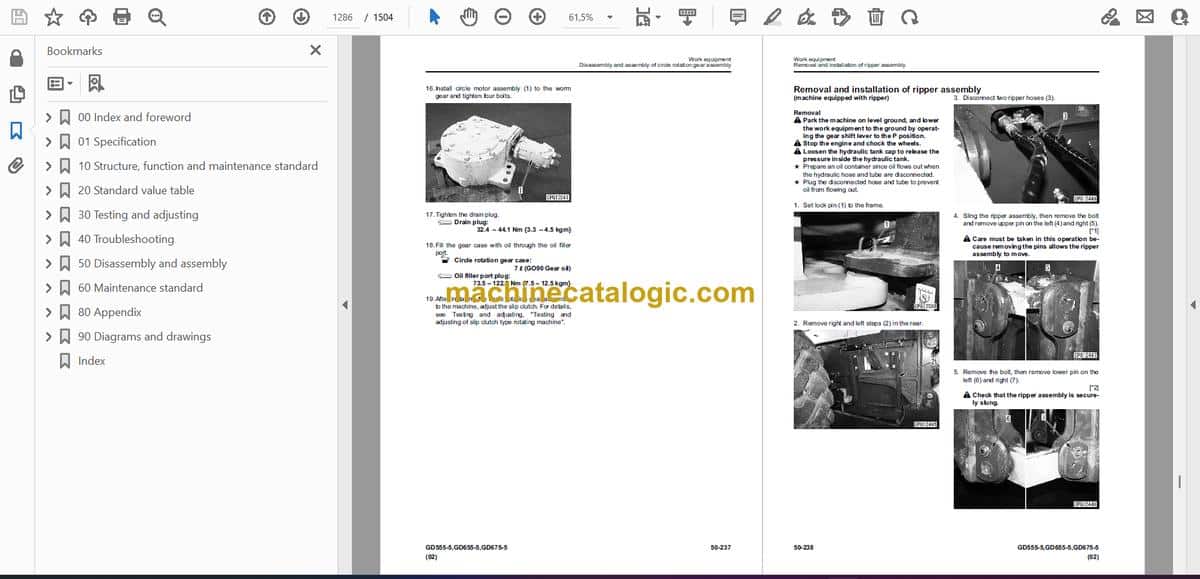
- Removal and installation of circle rotation gear assembly
- Disassembly and assembly of circle rotation gear assembly
- Removal and installation of ripper assembly
- Cab and its attachments
- Removal and installation of operator cab assembly
- Removal and installation of floor frame assembly
- Removal and installation of operator cab glass (adhered glass)
- Removal and installation of air conditioner unit assembly
- Electrical system
- Removal and installation of engine controller assembly
- Removal and installation of machine monitor assembly
- Removal and installation of transmission controller assembly
- Removal and installation of KOMTRAX terminal assembly
- 60 Maintenance standard
- Engine and Cooling
- Engine mount and transmission mount
- Cooling system
- Cooling fan motor
- Power train system
- Transmission control
- Torque converter
- Transmission
- Main relief valve and torque converter relief valve
- Front axle
- Final drive (no differential specification)
- Final drive (differential/ differential lock specification)
- Differential lock solenoid valve
- Tandem drive
- Brake system
- Slack adjuster
- Wheel brake
- Parking brake
- Hydraulic system
- Power train pump
- Control valve
- Hydraulic cylinder
- Work equipment
- Circle and drawbar
- Blade
- Lifter
- Circle rotation gear
- 80 Appendix
- Precautions before work
- Air conditioner
- Precautions for refrigerant
- Air Conditioner Components
- Structure and Function of Refrigeration System
- Overview of Refrigeration System
- Air Conditioner Unit
- Compressor
- Condenser
- Receiver drier
- Air conditioner control panel
- Procedure for check and troubleshooting
- Circuit diagram and layout of connector pins
- System diagram
- Detail of air conditioner unit
- Parts and connectors layout
- Testing air leakage (ducts)
- Check with self-diagnosis (control panel display)
- Testing temperature control
- Testing Fresh/Recirc air changeover
- Testing evaporator temperature sensor
- Testing relays
- Testing blower amp
- Troubleshooting Chart 1
- Troubleshooting Chart 2
- Information in troubleshooting table
- Troubleshooting for power supply system (Air conditioner does not operate)
- Troubleshooting of compressor and refrigerant system (Air is not cooled)
- Troubleshooting for blower motor system (Air does not come out or air flow is improper)
- Troubleshooting for temperature control
- Troubleshooting for FRESH/RECIRC air changeover
- Troubleshooting with gauge pressure
- Connection of service tool
- Precautions for disconnecting and connecting air conditioner piping
- Handling compressor oil
- 90 Diagrams and drawings
- Hydraulic diagrams and drawings
- Symbols used in hydraulic circuit diagrams
- Hydraulic circuit diagram
- Power train hydraulic circuit diagram
- Differential hydraulic circuit diagram
- Electrical diagrams and drawings
- Symbols used in electric circuit diagrams
- Electrical circuit diagram
- Index
Komatsu


