Format: PDF (Printable Document)
File Language: English
File Pages: 507
File Size: 71.36 MB (Speed Download Link)
Brand: Komatsu
Model: HD1500-8 Dump Truck
Book No: GEN00162-13
Serial No: 81001 and up
Type of Document: Field Assembly Manual
$ 39
1-1 Parts overview (main components only)
1-2 Dimensions of main components
3-1 Rough schedule of assembling and welding (for normal disassembly packing)
3-2 Layout of work space
4 Facility, jig and consumable parts list
Field assembly instruction
0010 Oil, grease and coolant
0020 Amount of oil, grease and coolant
A00010 Rear axle assembly
A00030 Installation of tire and wheel assembly (inner)
A00040 Installation of tire and wheel assembly (outer)
A00050 Bare machine stationary and rear axle connection
A00070 Installation of rear suspension
A00100 Installation of R.H. front support
A00200 Installation of exhaust pipe sub-assembly
A00250 Installation of exhaust pipe sub-assembly – 1
A00252 Part No. Part name Q’ty State of parts(1) 562-02-3B320 V-COUPLING 1 Unit shipmentImpact wrenchSocketsInstallation of exhaust pipe sub-assembly – 2
A00254 Installation of exhaust pipe fire prevention cover
A00300 Fixing of exhaust pipe
A00350 Installation of exhaust pipe lower cover
A00400 Installation of rear axle rod
A00500 Installation of fuel tank
A00600 Installation of fuel tank
A00700 Installation of front axle assembly (R.H.)
A00800 Installation of front axle assembly (L.H.)
A00810 Installation of hub odometer to front axle assembly (L.H.)
A00900 Installation of tie rod and steering cylinder to front axle (R.H.)
A01000 Installation of tie rod and steering cylinder to front axle (L.H.)
A01100 Fixing of the front axle (R.H.) connector
A01200 Fixing of front axle (L.H.) connector
A01250 Installation of tire and wheel assembly (front)
A01400 Connection of grease hose to rear suspension pin of rear axle
A01500 Fixing of upper rod
A01550 Installation of rear axle rods (lower)
A01600 Installation of transmission – rear axle flow drive shaft
A01700 Installation of rear propeller guard
A01800 ASR valve assembly – rear axle pipe connection
A01900 ASR valve assembly – rear axle pipe connection and fixing
A02000 Connection of fuel hose
A02100 Connection of fuel hose
A02200 Left side pipe installation of auto grease injector sub-assembly
A02300 Left side pipe installation of auto grease injector sub-assembly
A02400 Right side pipe installation of auto grease injector sub-assembly
A02500 Right side pipe installation of auto grease injector sub-assembly
A02600 Pipe installation of auto grease injector sub-assembly
A02700 Pipe connection of front axle (L.H.) oil cooling
A02800 Pipe connection of front axle (R.H.) oil cooling
A02900 Installation of battery isolator
A03000 Installation of battery isolator cover
A03100 Cable wiring of battery isolator
A03200 Cable wiring of battery isolator
A03300 Connection of fuel tank harness
A03400 Connection of front axle (L.H.) and front brake lineaxle (L.H.)
A03500 Connection of front axle (R.H.) and front brake lineaxle (R.H.)
A03600 Grease tube fixing of front axle (L.H.)
A03700 Grease tube fixing of front axle (R.H.)
A03800 Fixing of grease injector hose (R.H.)
A03900 Fixing of grease injector hose (R.H.)
A04000 Fixing of grease injector hose (R.H.)
A04100 Fixing of grease injector hose (L.H.)
A04200 Fixing of grease injector hose (L.H.)
A04300 Fixing of grease injector hose (L.H.)
A04400 Fixing of grease injector hose (L.H.)
A04500 Installation of air cleaner assembly
A04600 Grease tube fixing of front axle (L.H.) upper pin
A04700 Grease tube fixing of front axle (R.H.) upper pin
A04800 Grease tube fixing of front axle (R.H.) lower pin
A04900 Hose connection of hydraulic oil tank
A05000 Hose connection of hydraulic oil tank
A05100 Hose connection of rear cooling pump
A05200 Installation of hydraulic oil tank
A05300 Installation of hydraulic oil tank
A05400 Ground connection of hydraulic oil tank
A05500 Pipe connection of rear cooling pump – hydraulic oil tank
A05600 Cooling line connection of rear axle – brake
A05700 Pipe connection of hydraulic oil tank – transmission
A05800 Hose connection of front cooling pump – hydraulic oil tank
A05900 Suction tube connection of hydraulic oil tank
A06000 Hose connection of hydraulic oil tank – transmission
A06100 Connection of brake cooling tube (L.H.)
A06200 Connection of brake cooling tube (L.H.)
A06300 Wiring connection of battery cable
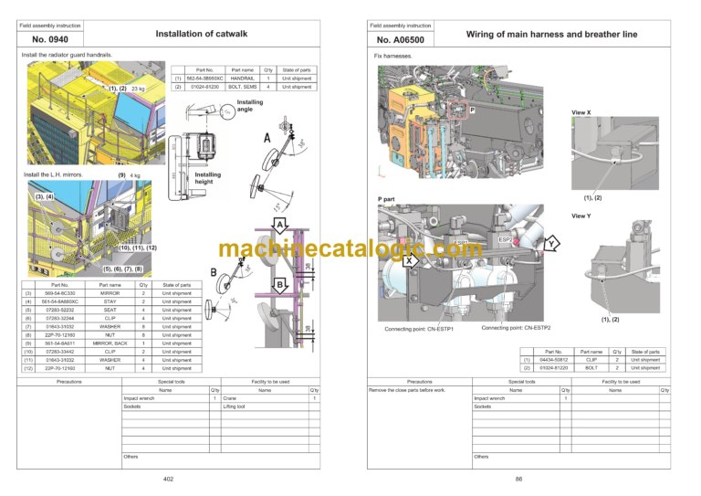
A06400 Wiring of main harness and breather line
A06500 Wiring of main harness and breather line
A06600 Wiring of breather line
A06700 Wiring of breather line
A06800 Wiring of breather line
A06900 Pump pipe connection of hydraulic oil tank – transmission
A07000 Connection and fixing of transmission – drain hose
A07100 Hose connection of hydraulic oil tank – engine and radiator
A07120 Installation of battery box
A07125 Battery box wiring -1
A07126 Battery box wiring -2
A07127 Battery box wiring -3
A07128 Battery box wiring -4
A07130 Connection of R.H. and L.H. front brake lines
A07140 Installation of accumulator
A07141 Connection of accumulator hose
A07142 Connection of accumulator hose at right of battery box -1
A07143 Connection of accumulator hose at right of battery box -2
A07145 Battery box bottom right piping disaster prevention cover assembly
A07146 Battery box right side protection cover assembly
A07150 Installation of auto grease pump
A07200 Fixing of wiring harness for auto grease pump
A07300 Connection of auto grease pump – main harness
A07305 Connection of auto grease pump – main harness (Graco specification)
A07400 Upper harness connection of front axle (R.H.)
A07500 Installation of engine room switch
A07600 Harness wiring under R.H. platform
A07700 Harness wiring under R.H. platform
A07800 Harness wiring under R.H. platform
A08000 Installation of CAB support
A08100 Installation of CAB support
A08200 Installation of refill control box
A08300 Hose connection of refill control box
A08400 Connection and fixing of heater hose
A08500 Installation of guard bracket under air intake
A08600 Installation of R.H. guard under air intake
A08610 Installation of L.H. guard under air intake
A08700 Installation of L.H. front support
A08800 Installation of R.H. front support
A09400 Installation of air intake
A09500 Installation of air intake
A09600 Installation of air intake
A09700 Installation of air intake
A09800 Fixing and connection of air intake wiring harness
A10000 Installation of bracket upper air intake
A10100 Fixing of air intake tube
A10200 Installation of VHMS box
A10210 Installation of VHMS box
A10300 Installation of diagonal ladder step
A10400 Installation of diagonal ladder step
A10500 Installation of diagonal ladder step
A10600 Installation of diagonal ladder step
A10700 Installation of diagonal ladder step
A10750 Installation of lower step toe guard
A10800 Installation of diagonal ladder step
A10900 Installation of diagonal ladder step
A10901 Installation of diagonal ladder step 7 6HA89A
A10905 Installation of diagonal ladder step 7 6HA89B
A10910 Sub-assembly of diagonal ladder step and radar
A11000 Installation of diagonal ladder step
A11001 Installation of reflector box
A11005 Installation of diagonal ladder step 8 6HA89B
A11010 Sub-assembly of R.H. radar
A11020 Sub-assembly of R.H. radar
A11100 Installation of diagonal ladder step
A11300 Installation of R.H. platform (R.H. support)
A11400 Installation of R.H. platform (R.H. support)
A11450 Installation of mudguard under R.H. platform
A11500 Installation of R.H. side ladder step
A12000 Harness wiring under R.H. platform
A12100 Harness wiring under R.H. platform
A12200 Harness wiring under R.H. platform
A12400 Installation of rear ladder
A12500 Installation of R.H. handrail
A12600 Installation of R.H. handrail
A12650 Installation of side camera
A12655 Installation of side camera 6HA89B
A12700 Installation of CAB assembly
A12800 Installation of radiator
A12801 Installation of R.H. and L.H. rods of radiator
A12802 Adjustment procedure of fan and radiator shroud
A12810 Connection of hose between radiator and oil cooler
A12815 Installation of fan guard
A12820 Installation of radiator piping -1
A12821 Installation of radiator piping -2
A12822 Installation of radiator piping -3
A12823 Installation of radiator piping -4
A12824 Installation of radiator piping -5
A12830 Fixing of radiator drain hose and installation of cover
A12831 Fixing of radiator drain hose and connection of hydraulic tank hose
A12835 Connection and fixing of air conditioner hose -1
A12836 Connection and fixing of air conditioner hose -2
A12840 Installation of top hood support
A12841 Installation of top hood
A12843 Battery box bottom left piping disaster prevention cover assembly
A12850 Connection and fixing of heater hose -1
A12851 Connection and fixing of heater hose -2
A12855 Fixing of radiator hose water tube
A12860 Installation of L.H. radiator guard
A12861 Installation of R.H. radiator guard
A12865 Installation of radiator guard upper cover and handrail
A12867 Installation of radiator grille
A12868 Installation of radiator curtain
A12900 Installation of washer tank
A13000 Installation of CAB assembly
A13050 Installation of CAB step
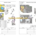
A13100 Installation of catwalk
A13200 Installation of catwalk
A13300 Installation of catwalk
A13400 Installation of catwalk
A13450 Installation of catwalk toe guards
A13460 Installation of catwalk assembling step
A13500 Mounting of CAB assembly
A13600 Mounting of CAB assembly
A13610 Wiring of L.H. mirror with heater
A13650 Installation of CAB assembly and drain hose
A13700 Main harness and transmission harness wiring
A13790 Wiring procedure between cab and antenna pole 1
A13791 Wiring procedure between cab and antenna pole 2
A13800 GPS harness and KOMTRAX harness connection
A13900 GPS harness and KOMTRAX harness connection
A14000 GPS harness and KOMTRAX harness connection
A14100 GPS/KOMTRAX/Antenna harness wiring
A14200 GPS/KOMTRAX/Antenna harness wiring
A14250 GPS/KOMTRAX/Antenna harness wiring
A14300 GPS/KOMTRAX/Antenna harness wiring
A14350 Modem-GPS/KOMTRAX/Antenna harness wiring
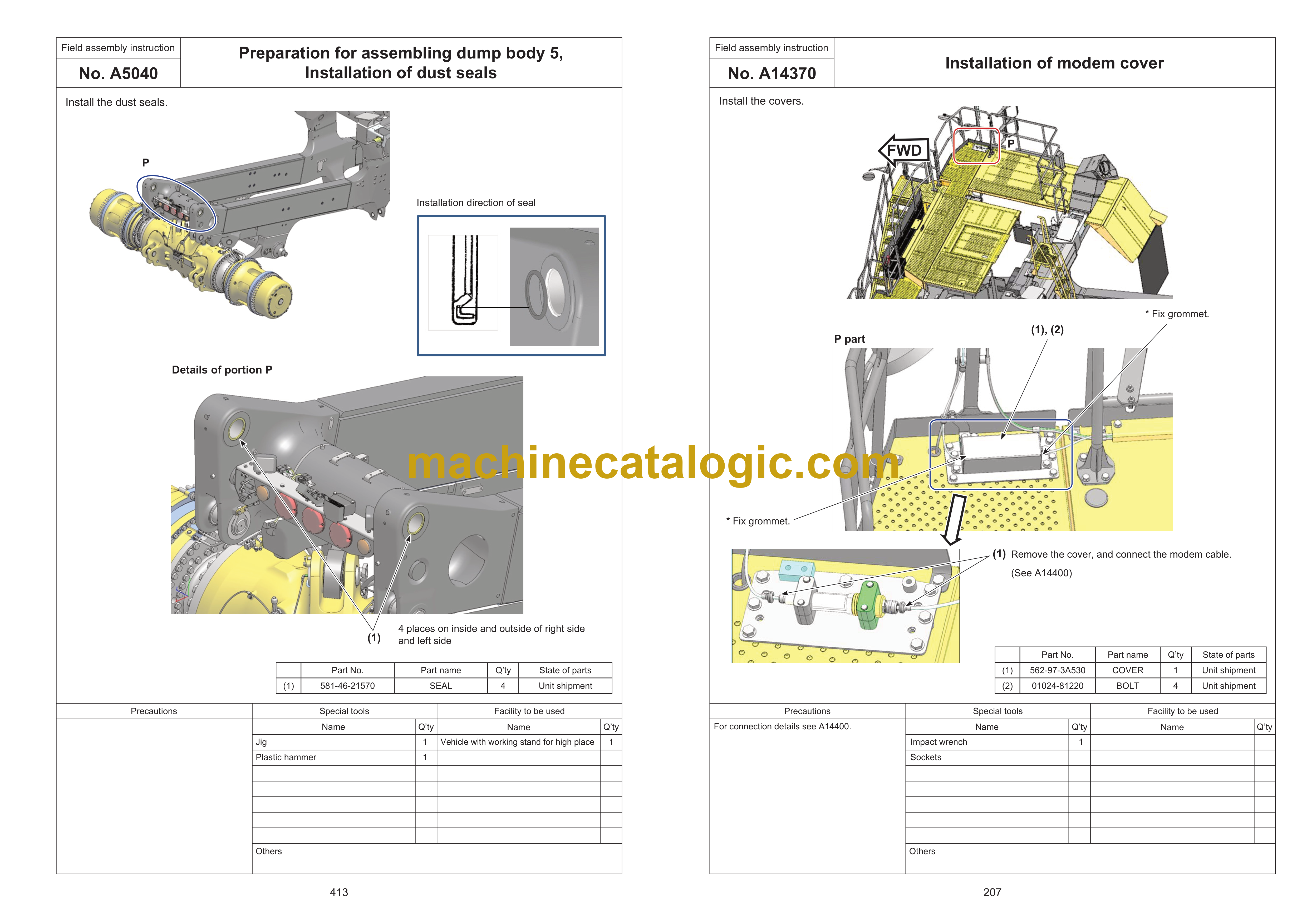
A14370 Installation of modem cover
A14400 Connection of modem and wireless LAN harness
A14450 Installation of GPS/KOMTRAX/Antenna harness cover
A14500 GPS/KOMTRAX/Antenna harness wiring
A14510 Installation of R.H. platform ORBCOMM pole
A14520 Wiring and installation of R.H. platform antennas
A14530 Wiring and installation of R.H. platform antennas
A14550 GPS/KOMTRAX/Antenna harness wiring
A14600 GPS/KOMTRAX/Antenna harness wiring
A14700 GPS/KOMTRAX/Antenna harness wiring
A14750 GPS/KOMTRAX/Antenna harness wiring
A14900 Fixing of main harness under right CAB
A14920 Fixing of main harness under CAB
A14940 Fixing of main harness under CAB – CN-SUFL
A14960 Fixing of main harness under CAB
A15050 Fixing of main harness under right CAB
A15100 Fixing of main harness under right CAB
A15200 Fixing of main harness under right CAB
A15300 Fixing of main harness under right CAB
A15400 Fixing of main harness under right CAB
A15500 Fixing of main harness under right CAB
A15550 Installation of engine shutdown switch box
A15560 Installation of junction box
A15570 Installation of heater fuse box
A15600 Main harness fixing of front L.H. light support
A15700 Main harness fixing of front L.H. light support
A15800 Main harness fixing of front L.H. light support
A15900 Main harness fixing of front L.H. light support
A16000 Connection of air compressor wiring harness
A16100 Connection of air compressor wiring harness
A16200 Wiring of harness leading to radiator
A16300 Wiring of harness leading to radiator
A16400 Wiring of harness leading to radiator
A16500 Wiring of harness leading to radiator
A16900 Monitor harness wiring (under R.H. platform)
A17300 Installation of ladder lamp
A17400 Wiring of harness leading to R.H. fender lamp
A17500 Installation of protection bracket for harness leading to R.H. fender lamp
A17600 Installation of mudguard
A17610 Installation of rear mudguard for catwalk
A17700 Installation of R.H. platform mudguard
A18700 Installation of L.H. fender
A18710 Installation of L.H. fender
A18800 Installation of R.H. fender
A18810 Installation of R.H. fender
A18900 Installation of L.H. fender mudguard
A19000 Installation of R.H. fender mudguard
A19100 L.H. fender harness wiring
A19200 L.H. fender harness wiring
A19300 L.H. fender harness wiring
A19400 Wiring of R.H. fender working lamp harness
A19500 Wiring of L.H. fender working lamp harness
A19600 Installation of front light covers, L.H. and R.H.
A19610 Installation of L.H. fog lamp
A19620 Installation of R.H. fog lamp
A19700 Installation of catwalk
A19710 Installation of catwalk mirror
A19720 Connection and fixing of wiring harness for L.H. mirror with heater
A19800 Installation of R.H. platform mirror
A19810 Installation of R.H. platform mirror
A19820 Connection and fixing of wiring harness for R.H. mirror with heater
A20700 Installation of transmission under guard
A20800 Installation of cab front step cover
A20900 Installation of covers under the cab
A21000 Installation of covers under the cab
A22000 Installation of quick charge hose
A22010 Installation of quick charge hose
A22020 Installation of quick charge box
A22100 Installation of radiator curtain
A23000 Installation of fire extinguisher
A23010 Installation of fire extinguisher
A23900 Installation of L.H. side cover – 1
A23910 Installation of L.H. side cover -2
A23920 Installation of L.H. side cover -3
A23950 Installation of R.H. side cover – 1
A23960 Installation of R.H. side cover – 2
A23970 Installation of R.H. side cover -3
A24000 Installation of L.H. side cover
A25000 Installation of tire stopper
A29000 Air bleeding procedure of brake
A29100 Starting engine
A29200 Air bleeding of steering cylinders
A29300 Air conditioner gas filling
A30000 Preparation for mounting of dump body
A30010 Preparation for mounting of 78 dump body
A30100 Preparation for mounting of dump body
A30110 Preparation for mounting 78 dump body
A30200 Preparation for mounting dump body
A30300 Preparation for mounting dump body
A30350 Preparation for mounting dump body – Installation of dust seals
A30400 Mounting of dump body
A30410 Mounting of dump body – Removal of extension/ retraction prevention plate
A30500 Mounting of dump body – Adjustment of bottom mount
A30600 Preparation for welding mount on dump body front side
A30700 Mounting of dump body – Welding of body mount
A30800 Mounting of dump body – Welding of dump body heating tube
A30810 Mounting of dump body – Welding of dump body heating tube
A30900 Dump body mounting – Installation of exhaust pipe cover
A30930 Mounting of 78 dump body – Installation of exhaust pipe cover 1
A30940 Mounting of 78 dump body – Installation of exhaust pipe cover 2
A31000 Dump body mounting – Grease piping
A31100 Dump body mounting – Installation of dump body mudguard
A31200 Fixing of positioner sensor rod
A31300 Installation procedure for dump body angle sensor and lever
A33000 Adjustment procedure of suspension gas – Front
A33100 Adjustment procedure of suspension gas – Rear
A33200 Procedure for bleeding air from hoist cylinder
A33300 KomVision
A33310 KomVision
A33320 KomVision
A33330 KomVision
A33340 KomVision
A33350 Check before starting KomVision
A33400 Sticking tie-off decal
A33410 Sticking dump body tie-off decals – 1
A33420 Sticking dump body tie-off decals – 2
A33430 Sticking tie-off decals to dump body for compliancewith Australian regulations – 1
A33440 Sticking tie-off decals to dump body for compliancewith Australian regulations – 2
B10300 Installation of power ladder lower step
B10310 Installation of power ladder lower step handrail
B10320 Fixing handrail of power ladder lower step
B10330 Installation of power ladder
B10340 Installation of power ladder angle sensor
B10350 Installation of power ladder angle sensor cover
B10360 Installation of power ladder handrail
B10370 Installation of power ladder pump piping 1
B10380 Installation of power ladder pump piping 2
B10390 Installation of power ladder piping cover
B10400 Installation of power ladder upper step
B10500 Installation of diagonal ladder of power ladder
B10600 Installation of emergency ladder of power ladder
B10700 Installation of power ladder handrail
B10800 Installation of emergency ladder gate of power ladder
B10900 Installation of power ladder surrounding monitor
B10901 Connection of power ladder step harness
B10910 Sub-assembly of power ladder step monitor
B11000 Installation of power ladder surrounding monitor 2
B11010 Sub-assembly of R.H. monitor
B11020 Sub-assembly of R.H. monitor 2
B11050 Installation of step for going up and down
B11100 Installation of power ladder front camera
B11200 Oil refilling of power ladder
B11210 Adjustment of power ladder operation time
C-0010 Preparation of dump body welding
C-0020 Assembly work of dump body
C-0030 Assembly work of dump body
C-0040 Tack welding of dump body
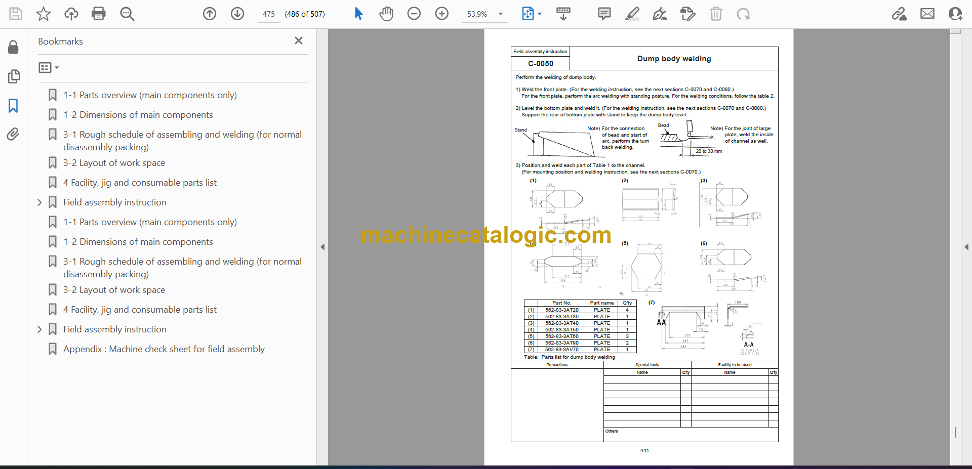
C-0050 Dump body welding 1
C-0060 Dump body welding 2
C-0070 Dump body welding procedure
C-0080 Dump body welding procedure
C-0090 Turning over of dump body
C-0100 Welding of dump body protector
C-0110 Welding of dump body protector
C-0111 Welding of dump body protector
C-0120 Weld finishing and painting of dump body
C-0200 Preparation of dump body welding (Side extension)
C-0210 Dump body welding – 1 (Side extension)
C-0220 Dump body welding – 2 (Side extension)
C-0230 Dump body welding – 3 (Side extension)
C-0240 Dump body welding – 4 (Side extension)
C-0250 Dump body welding procedure – 1 (Side extension)
C-0260 Dump body welding procedure – 2 (Side extension)
C-0270 Dump body welding procedure – 3 (Side extension)
C-0280 Weld finishing and painting of dump body (Side extension)
– Method for checking and inflating tire
1-1 Parts overview (main components only)
1-2 Dimensions of main components
3-1 Rough schedule of assembling and welding (for normal disassembly packing)
3-2 Layout of work space
4 Facility, jig and consumable parts list
Field assembly instruction
0010 Oil, grease and coolant
0020 Amount of oil, grease and coolant
0100 Bare machine stationary and rear axle connection
0200 Installation of tire and wheel assembly 1
0205 Installation of tire and wheel assembly 2
0500 Installation of diagonal ladder step
0510 Installation of diagonal ladder step
0520 Installation of diagonal ladder step
0530 Installation of diagonal ladder step
0540 Installation of diagonal ladder step
0550 Installation of diagonal ladder step
0560 Installation of diagonal ladder step
0560S Sub-assembly of diagonal ladder step and radar
0570 Installation of diagonal ladder step
0580 Installation of diagonal ladder step
0600 Installation of R.H. side ladder
0610 Installation of side camera
0620 Installation of ladder lamp
0630 Installation of rear ladder
0700 Installation of R.H. handrail
0710 Installation of R.H. handrail 2
0720 Installation of R.H. platform mirror
0750 Installation of R.H. platform ORBCOMM pole
0760 Wiring and installation of R.H. platform antennas
0770 Wiring and installation of R.H. platform antennas
0790 Installation of R.H. platform mudguard
0800 Preparation for mounting of CAB assembly
0810 Installation of CAB assembly
0820 Installation of CAB assembly
0830 Installation of CAB assembly 4
0840 Installation of CAB step
0850 Installation of CAB assembly 6
0860 Installation of washer tank
0890 Restoration of hood after mounting the CAB assembly
0900 Installation of catwalk
0910 Installation of catwalk
0920 Installation of catwalk
0930 Installation of catwalk
0940 Installation of catwalk
1500 Installation of transmission under guard
1600 Installation of muffler
3100 Air bleeding procedure of brake
3200 Starting engine
3300 Air bleeding of steering cylinders
5000 Preparation of mounting of dump body
5010 Preparation for mounting of dump body 2
5015 Preparation for mounting 78 dump body
5020 Preparation for mounting dump body 3
5030 Preparation for mounting dump body 4
A5040 Preparation for assembling dump body 5, Installation of dust seals
5100 Mounting dump body 1
5110 Mounting of dump body 1-2, Removal of extension/retraction prevention plate
5120 Mounting of dump body 2 (Adjustment of bottom mount)
5130 Preparation for welding mount on dump body front side
5140 Mounting dump body 4, Welding of body mount
5150 Mounting dump body 5, Welding of dump body heating tube
5155 Mounting of 78 dump body – Welding of dump body heating tube
5160 Dump body mounting – Installation of exhaust pipe cover
5163 Mounting of 78 dump body – Installation of exhaust pipe cover 1
5164 Mounting of 78 dump body – Installation of exhaust pipe cover 2
5170 Dump body mounting – Grease piping
5180 Dump body mounting – Installation of dump body mudguard
5190 Fixing of positioner sensor rod
5195 Installation procedure for dump body angle sensor and lever
5900 Adjustment procedure of front suspension gas
5910 Adjustment procedure of rear suspension gas
5920 Procedure for bleeding air from hoist cylinder
6000 KomVision
6010 KomVision
6020 KomVision
6030 KomVision
6040 KomVision
6050 Check before starting KomVision
6060 Method for checking and inflating tire
C-0010 Preparation of dump body welding
C-0020 Assembly work of dump body
C-0030 Assembly work of dump body
C-0040 Tack welding of dump body
C-0050 Dump body welding
C-0060 Dump body welding
C-0070 Dump body welding procedure
C-0080 Dump body welding procedure
C-0090 Turning over of dump body
C-0100 Welding of dump body protector
C-0110 Welding of dump body protector
C-0111 Welding of dump body protector
C-0120 Weld finishing and painting of dump body
Appendix : Machine check sheet for field assembl


