These Komatsu HD325-7R, HD405-7R rigid dump trucks are production trucks for quarries, mines, and heavy earthmoving, where downtime burns money fast. The Komatsu HD325-7R, HD405-7R Rigid Dump Truck Shop Manual (SEN02373-19) is what shops and fleet managers reach for when a truck is down in the bay, not when someone just needs operating tips. People usually buy this kind of manual to plan major repairs, support diagnostics, and standardize work between shifts and sites. If you’re trying to keep parts on the shelf and avoid repeat failures, this is the right document type.
What this manual helps you do
- Trace hydraulic, brake, and steering issues using the kind of troubleshooting steps shops rely on for rigid dump trucks.
- Diagnose engine, transmission, and driveline faults with the procedures you’d expect in a workshop-level repair guide.
- Follow teardown and reassembly sequences for major components so technicians don’t waste time guessing the order.
- Check adjustment points and set up linkages, brakes, and controls to factory spec using the reference data these usually provide.
- Verify systems after repair with the inspection and testing routines that are standard in a Komatsu shop manual.
Who this is for
This is aimed at field techs, shop mechanics, and fleet managers who schedule and oversee heavy repairs. It’s overkill if you’re just operating the truck or doing daily/weekly checks; in that case you’d want the Operation & Maintenance Manual instead.
FAQ
Q: Is this a searchable PDF I can download and print?
A: Yes, it’s a digital manual you can keep on a laptop, search by keyword, and print pages for the shop wall.
Q: Is this deep enough for full overhauls, or just light service?
A: This is a shop manual, so it’s meant for workshop-level diagnostics, disassembly, repair, and reassembly, not just routine maintenance.
Q: How do I know it matches my exact HD325-7R or HD405-7R?
A: Check your model designation and match the book reference SEN02373-19; if your plate doesn’t match those models, you’ll need a different manual.
Bottom line: If you’re planning or supervising real repair work on HD325-7R or HD405-7R trucks, this is the one you want; if you only need basic operation and service intervals, keep looking for the O&M manual instead.
📘 Show Index
Table of Contents:
- 00 Index and foreword
- Index
- Composition of shop manual
- Table of contents
- Foreword and general information
- Safety notice
- How to read the shop manual
- Explanation of terms for maintenance standard
- Handling of electric equipment and hydraulic component
- Handling of connectors newly used for engines
- How to read electric wire code
- Precautions when carrying out operation
- Method of disassembling and connecting push-pull type coupler
- Standard tightening torque table
- Conversion table
- 01 Specification
- Specification and technical data
- Specification drawing
- Specifications
- Specifications (Vietnam spec)
- Weight table
- Fuel, coolant and lubricants
- 10 Structure, function and maintenance standard
- Engine and cooling system
- Radiator, oil cooler, aftercooler
- Output shaft
- Power train, Part 1
- Power train skeleton
- Drive shaft
- Torque converter and transmission hydraulic piping
- Power train charge pump
- Retarder cooling pump
- Torque converter
- Torque converter valve
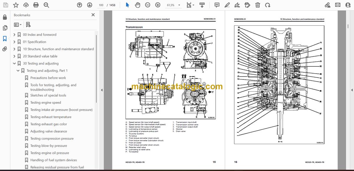
- Transmission
- Transmission control valve
- ECMV
- Power train, Part 2
- Axle
- Differential
- Final drive
- Wheel
- Steering system
- Steering column
- Steering linkage
- Brake system
- Brake piping
- Brake valve
- Secondary brake valve
- Relay valve
- Front brake cut valve
- Accumulator charge valve
- Accumulator
- Slack adjuster
- Brake
- Proportional reducing valve
- Parking brake
- Parking brake solenoid
- Hand brake (retarder)
- Undercarriage and frame
- Suspension
- Suspension cylinder
- Rear axle support
- Hydraulic system
- Steering, hoist oil pressure piping diagram
- Dump body control
- Hydraulic tank
- Steering valve
- Cross-over relief valve
- Steering control valve
- Hoist valve
- EPC valve
- Steering cylinder
- Hoist cylinder
- Work equipment and steering pump
- Cab and its attachments
- ROPS cab
- Air conditioner
- Rear view monitor
- Electrical system, Part 1
- Electrical system, Part 2
- Automatic shift control system
- Transmission controller
- Auto emergency steering system
- Retarder control system
- Dump control lever
- Auto suspension system
- Electrical system, Part 3
- Payload meter II (card type)
- Payload meter (PLM) controller related
- Electrical system, Part 4
- Sensors, switches
- KOMTRAX terminal system (If equipped)
- 20 Standard value table
- Standard service value table
- Standard value table for engine
- Standard value table for machine
- Standard value table for machine (Vietnam spec)
- 30 Testing and adjusting
- Testing and adjusting, Part 1
- Precautions before work
- Tools for testing, adjusting, and troubleshooting
- Sketches of special tools
- Testing engine speed
- Testing intake air pressure (boost pressure)
- Testing exhaust temperature
- Testing exhaust gas color
- Adjusting valve clearance
- Testing compression pressure
- Testing blow-by pressure
- Testing engine oil pressure
- Handling of fuel system devices
- Releasing residual pressure from fuel system
- Testing fuel pressure
- Reduced cylinder mode operation
- No-injection cranking
- Testing fuel return rate and leakage
- Bleeding air from fuel circuit
- Testing the fuel circuit for leakage
- Testing and adjusting alternator belt tension
- Testing and adjusting fan belt tension
- Testing and adjusting air conditioner compressor belt tension
- Testing and adjusting, Part 2
- Testing torque converter stall speed
- Testing power train oil pressure
- Adjusting transmission speed sensor
- Testing brake oil pressure
- Testing of accumulator nitrogen gas pressure and procedure for charging accumulator with nitrogen gas
- Testing brake performance
- Testing and adjusting parking brake performance
- Releasing remaining pressure in brake circuit
- Bleeding air from brake circuit
- Testing wear of rear brake disc
- Testing wear of front brake pad
- Method for emergency release of parking brake
- Testing and adjusting front suspension cylinder
- Testing and adjusting inverted type rear suspension cylinder
- Testing and adjusting front suspension cylinder (mode selector hydraulic cylnder)
- Testing and adjusting hydraulic pressure in steering, hoist circuit
- Testing and adjusting dump EPC circuit oil pressure
- Air bleeding from steering cylinder
- Procedure for raising body in emergency
- Adjusting body positioner sensor
- Resetting method for dump body seating control
- Adjustment of tilt lock lever of steering wheel
- Handling of high voltage circuit of engine controller
- Adjusting transmission controller
- Method for emergency escape at electrical system failure
- Testing and adjusting, Part 3
- Setting and adjusting of devices
- Special functions of machine monitor (EMMS)
- Testing and adjusting, Part 4
- How to start operation of KOMTRAX terminal
- Lamp display of KOMTRAX terminal
- Pm Clinic check sheet
- Setting of card-type payload meter (PLM-) after installation or replacement
- Setting of payload meter
- 40 Troubleshooting
- Failure code table and fuse locations
- Failure codes table
- Fuse locations
- General information on troubleshooting
- Precautions before work
- Points to remember when performing troubleshooting
- How to proceed in troubleshooting
- Checks before troubleshooting
- Checking water pump for water leakag
- Classification and procedures of troubleshooting
- Information in troubleshooting table
- Troubleshooting method for disconnecting wiring harness of pressure sensor system
- Contents of troubleshooting table
- Connection table for connector pin numbers
- T-branch box and T-branch adapter table
- Troubleshooting by failure code, Part 1
- Failure code [1500L0] Dual engagement
- Failure code [15B0NX] Transmission oil filter: Clogging
- Failure code [15F0KM] R → F shifting abuse 1: Mistake in operation
- Failure code [15F0MB] R → F shifting abuse 2: Mistake in operation
- Failure code [15F7KM] Forward clutch disk abuse: Mistake in operation or setting
- Failure code [15G0MW] R clutch: Slipping
- Failure code [15G7KM] Reverse clutch disk abuse: Mistake in operation or setting
- Failure code [15H0MW] Hi clutch: Slipping
- Failure code [15J0MW] Lo clutch: Slipping
- Failure code [15K0MW] 1st clutch: Slipping
- Failure code [15L0MW] 2nd clutch: Slipping
- Failure code [15M0MW] 3rd clutch: Slipping
- Failure code [15N0MW] 4th clutch: Slipping
- Failure code [15SBL1] R clutch solenoid: Fill signal is ON when command current is OFF
- Failure code [15SBMA] R clutch solenoid: Malfunction
- Failure code [15SCL1] Hi clutch solenoid: Fill signal is ON when command current is OFF
- Failure code [15SCMA] Hi clutch solenoid: Malfunction
- Failure code [15SDL1] Lo clutch solenoid: Fill signal is ON when command current is OFF
- Failure code [15SDMA] Lo clutch solenoid: Malfunction
- Failure code [15SEL1] 1st clutch solenoid: Fill signal is ON when command current is OFF
- Failure code [15SEMA] 1st clutch solenoid: Malfunction
- Failure code [15SFL1] 2nd clutch solenoid: Fill signal is ON when command current is OFF
- Failure code [15SFMA] 2nd clutch solenoid: Malfunction
- Failure code [15SGL1] 3rd clutch solenoid: Fill signal is ON when command current is OFF
- Failure code [15SGMA] 3rd clutch solenoid: Malfunction
- Failure code [15SHL1] 4th clutch solenoid: Command current is OFF and fill signal is ON
- Failure code [15SHMA] 4th clutch solenoid: Malfunction
- Failure code [15SJMA] Lockup clutch solenoid: Malfunction
- Failure code [989A00] Engine over run prevention command signal: Operating
- Failure code [989D00] Rear section tipping over alarm: Alarm is activated
- Failure code [2F00KM] Parking brake: Mistake in operation or setting
- Failure code [2G42ZG] Front accumulator: Lowering of oil pressure
- Failure code [2G43ZG] Rear accumulator: Lowering of oil pressure
- Failure code [A570NX] Engine oil filter: Clogging
- Failure code [AA10NX] Air cleaner element: Clogging
- Failure code [AB00MA] Alternator: Malfunction
- Failure code [B@BAZG] Abnormal lowering of engine oil pressure: Lowering of oil pressure
- Failure code [B@BAZK] Engine oil: Level too low
- Failure code [B@BCZK] Lowering of radiator coolant: Lowering of level
- Failure code [B@BCNS] Engine: Overheat
- Failure code [B@C7NS] Rear brake oil: Overheat
- Failure code [B@CENS] Torque converter oil: Overheat
- Failure code [B@GAZK] Battery electrolyte level: Lowering of level
- Failure code [B@JANS] Steering oil: Overheat
- Troubleshooting by failure code, Part 2
- Failure code [CA111] Abnormality in engine controller
- Failure code [CA115] Engine Ne or Bkup speed sensor error
- Failure code [CA122] Charge (boost) pressure sensor high error
- Failure code [CA123] Charge (boost) pressure sensor low error
- Failure code [CA131] Throttle sensor high error
- Failure code [CA132] Throttle sensor low error
- Failure code [CA135] Engine oil pressure sensor high error
- Failure code [CA141] Engine oil pressure sensor low error
- Failure code [CA144] Coolant temperature sensor high error
- Failure code [CA145] Coolant temperature sensor low error
- Failure code [CA153] Charge (boost) temperature sensor high error
- Failure code [CA154] Charge (boost) temperature sensor low error
- Failure code [CA187] Sensor power supply 2 low error
- Failure code [CA221] Atmospheric pressure sensor high error
- Failure code [CA222] Atmospheric pressure sensor low error
- Failure code [CA227] Sensor power supply 2 high error
- Failure code [CA234] Engine overspeed
- Failure code [CA238] Ne speed sensor power supply error
- Failure code [CA263] Fuel Temperature Sensor High Error
- Failure code [CA265] Fuel Temperature Sensor Low Error
- Failure code [CA271] PCV1 Short circuit
- Failure code [CA272] PCV1 Disconnection
- Failure code [CA273] PCV2 Short circuit
- Failure code [CA274] PCV2 Disconnection
- Failure code [CA322] Injector #1 open/short error
- Failure code [CA323] Injector #5 open/short error
- Failure code [CA324] Injector #3 open/short error
- Failure code [CA325] Injector #6 open/short error
- Failure code [CA331] Injector #2 open/short error
- Failure code [CA332] Injector #4 open/short error
- Failure code [CA342] Calibration code inconsistency
- Failure code [CA351] Injectors drive circuit error
- Failure code [CA352] Sensor power supply 1 low error
- Failure code [CA386] Sensor power supply 1 high error
- Failure code [CA431] Idle validation switch error
- Failure code [CA432] Idle validation action error
- Failure code [CA441] Battery voltage low error
- Failure code [CA442] Battery voltage high error
- Failure code [CA449] Common rail pressure high error 2
- Failure code [CA451] Common rail pressure sensor high error
- Failure code [CA452] Common rail pressure sensor low error
- Failure code [CA553] Common rail pressure high error 1
- Failure code [CA554] Common rail pressure sensor in range error
- Failure code [CA559] Supply pump pressure very low error 1
- Failure code [CA689] Engine Ne speed sensor error
- Failure code [CA731] Engine Bkup speed sensor phase error
- Failure code [CA757] All continuous data lost error
- Failure code [CA778] Engine Bkup speed sensor error
- Troubleshooting by failure code, Part 3
- Failure code [CA1633] KOMNET datalink timeout error
- Failure code [CA2185] Throttle sensor power supply voltage high error
- Failure code [CA2186] Throttle sensor power supply voltage low error
- Failure code [CA2249] Supply pump pressure very low error 2
- Failure code [CA2555] Intake air heater relay open circuit error
- Failure code [CA2556] Intake air heater relay short circuit error
- Failure code [D19HKB] Stop lamp relay output system: Short circuit
- Failure code [D5ZKKZ] Front brake cut-off solenoid valve: Disconnection or short circuit
- Failure code [DAF9KM] Machine monitor: Wrong operation or wrong setting
- Failure code [DAFRKR] Abnormal CAN communication (machine monitor): Abnormal communication
- Failure code [DAQ0KK] Transmission controller direct power supply: Lowering of source voltage
- Failure code [DAQ0KT] Transmission controller nonvolatile memory: Abnormality in controller
- Failure code [DAQ2KK] Transmission controller solenoid power source: Power source voltage too low
- Failure code [DAQ9KQ] Transmission controller: Disagreement of model selection
- Failure code [DAQRKR] Abnormal CAN communication (Transmission): Abnormal communication
- Failure code [DAQRMA] Transmission controller option setting: Malfunction
- Failure code [DB10KT] Retarder controller nonvolatile memory: Abnormality in controller
- Failure code [DB12KK] Retarder controller solenoid power source: Power source voltage too low
- Failure code [DB13KK] Retarder controller direct power source: Power source voltage too low
- Failure code [DB19KQ] Retarder controller model selection signal: Disagreement of model selection signals
- Failure code [DB1RKR] CAN communication (retarder controller): Communication disabled
- Failure code [DB1RMA] Retarder controller option setting: Defective function
- Failure code [DB1SKQ] Model selection: Wrong information
- Failure code [DB2RKR] CAN communication (engine controller): Communication disabled
- Failure code [DBB0KK] PLM controller: Low source voltage (input) or PLM controller_LED display: "n9" → "01"
- Failure code [DBB0KQ] PLM controller: Disagreement of model selection signals or PLM controller_LED display: "nF" → "11"
- Failure code [DBB3KK] PLM controller battery power supply: Low source voltage (input) or PLM controller_LED display: "n9" → "05"
- Failure code [DBB6KP] PLM controller 24V power supply output: Low output voltage or PLM controller_LED display: "n9" → "02"
- Failure code [DBBQKR] PLM controller CAN communication: Defective communication or PLM controller_LED display: "n8" → "02"
- Failure code [DBBRKR] Abnormal CAN communication (PLM) : Defective communication
- Failure code [DBC9KQ] Disagreement of model selection (ABS controller)
- Failure code [DBCRMA] Disagreement of option setting (ABS controller)
- Failure code [DDD7KX] Trouble in travel speed setting switch system: Out of input signal range (If equipped)
- Failure code [DDD8KA] ARSC system switch system: Disconnection
- Failure code [DDD8KB] ARSC system switch system: Short circuit
- Failure code [DDDAKA] ASR system switch: Disconnection (If equipped)
- Failure code [DDDAKB] ASR system switch: Short circuit
- Failure code [DDTHKA] Hi clutch fill switch: Disconnection
- Failure code [DDTJKA] Lo clutch fill switch: Disconnection
- Failure code [DDTKKA] 1st clutch fill switch: Disconnection
- Failure code [DDTLKA] 2nd clutch fill switch: Disconnection
- Failure code [DDTMKA] 3rd clutch fill switch: Disconnection
- Failure code [DDTNKA] R clutch fill switch: Disconnection
- Failure code [DDTPKA] 4th clutch fill switch : Disconnection
- Failure code [DF10KA] Gear shift lever: Disconnection
- Failure code [DF10KB] Gear shift lever: Short circuit
- Failure code [DGF1KX] Transmission oil temperature sensor: Out of input signal range
- Failure code [DGR2KZ] Retarder oil temperature sensor : Disconnection or short circuit
- Failure code [DGR6KX] Steering oil temperature sensor: Input signal out of range
- Failure code [DGT1KX] Torque converter oil temperature sensor: Out of input signal range
- Troubleshooting by failure code, Part 4
- Failure code [DHP4KY] Short circuit in suspension pressure sensor system (Front right) or PLM controller_LED display: "n5" → "44"
- Failure code [DHP4KZ] Disconnection or ground fault in suspension pressure sensor system (Front right) or PLM controller_LED display: "n5" → "43"
- Failure code [DHP5KY] Short circuit in suspension pressure sensor system (Front left) or PLM controller_LED display: "n5" → "54"
- Failure code [DHP5KZ] Disconnection or ground fault in suspension pressure sensor system (Front left) or PLM controller_LED display: "n5" → "53"
- Failure code [DHP6KA] (Suspension pressure sensor system (Rear right): Disconnection)
- Failure code [DHP6KX] (Failure in suspension pressure sensor system trouble (Rear right): Out of input signal range)
- Failure code [DHP6KY] Suspension pressure sensor system: Short circuit (Right rear) or PLM controller_LED display: "n5" → "64"
- Failure code [DHP6KZ] Suspension pressure sensor system: Disconnection or ground fault (Right rear) or PLM controller_LED display: "n5" → "63"
- Failure code [DHP7KA] (Suspension pressure sensor system (Rear left): Disconnection)
- Failure code [DHP7KX] (Failure in suspension pressure sensor system trouble (Rear left): Out of input signal range)
- Failure code [DHP7KY] Suspension pressure sensor system: Short circuit (Left rear) or PLM controller_LED display: "n5" → "74"
- Failure code [DHP7KZ] Suspension pressure sensor system: Disconnection or ground fault (Left rear) or PLM controller_LED display: "n5" → "73"
- Failure code [DHT5KX] (Torque converter oil pressure sensor: Out of input signal range)
- Failure code [DHT5L6] (Torque converter oil pressure sensor: Disagreement of run and stop condition with signal)
- Failure code [DHU2KX] (Front accumulator oil pressure sensor: Out of input signal range)
- Failure code [DHU3KX] (Rear accumulator oil pressure sensor: Out of input signal range)
- Failure code [DJF1KA] (Fuel level sensor: Disconnection)
- Failure code [DK30KX] Trouble in steering angle potentiometer
- Failure code [DK51L5] (Retarder lever potentiometer: Potentiometer signal is inconsistent with switch signal)
- Failure code [DK52KX] (Failure in hoist lever potentiometer 1: Out of input signal range)
- Failure code [DK53L8] (Failure in hoist lever potentiometer 2: Disagreement of analog signal)
- Failure code [DK54KX] (Body positioner sensor: Out of input signal range)
- Failure code [DKD0L6] (Failure in steering speed sensor: Disagreement of run and stop condition with signal) (If equipped)
- Failure code [DKH0KX] (Pitch angle sensor: Out of input signal range) (If equipped)
- Failure code [DKH1KX] Abnormality in clinometer sensor or PLM controller_LED display: "n4" → "33"
- Failure code [DLF1KA] (Transmission input shaft speed sensor: Disconnection)
- Failure code [DLF1LC] (Transmission input shaft speed sensor: Disagreement of revolution speed signal)
- Failure code [DLF2KA] (Transmission intermediate shaft speed sensor: Disconnection)
- Failure code [DLF2LC] (Transmission intermediate shaft speed sensor: Disagreement of revolution speed signal)
- Failure code [DLF8KA] Disconnection in wheel speed sensor (Right rear)
- Failure code [DLF8LC] Trouble in wheel speed sensor system (Right rear)
- Failure code [DLF9KA] Disconnection in wheel speed sensor (Left rear)
- Failure code [DLF9LC] Trouble in wheel speed sensor system (Left rear)
- Failure code [DLT3KA] (Transmission output shaft speed sensor: Disconnection)
- Failure code [DLT3LC] (Transmission output shaft speed sensor: Disagreement of revolution speed signal) (If equipped)
- Failure code [DLT4KA] (Transmission output shaft speed sensor: Disconnection) (If equipped)
- Failure code [DLT4MA] (Transmission output shaft speed sensor: Malfunction)
- Failure code [DV00KB] (Warning buzzer output: Short circuit)
- Failure code [DW35KZ] (Failure in output system of auto suspension solenoid 1: Disconnection or short circuit) (If equipped)
- Failure code [DW36KZ] (Failure in output system of auto suspension solenoid 2: Disconnection or short circuit) (If equipped)
- Failure code [DW72KZ] (Failure in kick-out solenoid output system: Disconnection or short circuit)
- Failure code [DW73KZ] (Failure in hoist select valve output system: Disconnection or short circuit)
- Failure code [DW78KZ] (Failure in rear brake BCV command output system: Disconnection or short circuit)
- Failure code [DWNBK4] Trouble in ASR shut-off valve (Valve keeps operating)
- Failure code [DWNBKA] Disconnection in ASR shut-off valve output circuit
- Failure code [DWNBKB] Ground fault in ASR shut-off valve output circuit
- Failure code [DWNBKY] Short circuit in ASR shut-off valve output circuit
- Failure code [DWNBMA] Trouble in ASR shut-off valve (Valve does not operate)
- Failure code [DX11K4] (Rear brake proportional pressure reducing solenoid valve: Out of control)
- Failure code [DX11KA] (Rear brake proportional pressure reducing solenoid valve output circuit: Disconnection)
- Failure code [DX11KB] (Rear brake proportional pressure reducing solenoid valve: Short circuit)
- Failure code [DX11KY] (Rear brake proportional pressure reducing solenoid valve: Short circuit to power source line)
- Failure code [DX11MA] (Rear brake proportional pressure reducing solenoid valve: Malfunction)
- Failure code [DX13KA] (Output circuit of hoist EPC valve: Disconnection)
- Failure code [DX13KB] (Output circuit of hoist EPC valve: Short circuit)
- Failure code [DX13KY] (Output circuit of hoist EPC valve: Short circuit with power source line)
- Troubleshooting by failure code, Part 5
- Failure code [DX17K4] Trouble in ASR proportional pressure reducing solenoid valve (right) (Valve keeps operating)
- Failure code [DX17KA] Disconnection in ASR proportional pressure reducing solenoid valve (right) output circuit
- Failure code [DX17KB] Ground fault in ASR proportional pressure reducing solenoid valve (right) output circuit
- Failure code [DX17KY] Short circuit in ASR proportional pressure reducing solenoid valve (right) output circuit
- Failure code [DX17MA] Trouble in ASR proportional pressure reducing solenoid valve (right) (Valve does not operate)
- Failure code [DX18K4] Trouble in ASR proportional pressure reducing solenoid valve (left) (Valve keeps operating)
- Failure code [DX18KA] Disconnection in ASR proportional pressure reducing solenoid valve (left) output circuit
- Failure code [DX18KB] Ground fault in ASR proportional pressure reducing solenoid valve (left) output circuit
- Failure code [DX18KY] Short circuit in ASR proportional pressure reducing solenoid valve (left) output circuit
- Failure code [DX18MA] Trouble in ASR proportional pressure reducing solenoid valve (left) (Valve does not operate)
- Failure code [DXH1KA] Lockup clutch solenoid output circuit: Disconnection
- Failure code [DXH1KB] Lock-up clutch solenoid output circuit: Short circuit
- Failure code [DXH1KY] Lockup clutch solenoid output circuit: Short circuit to power source line
- Failure code [DXH2KA] Hi clutch solenoid output circuit: Disconnection
- Failure code [DXH2KB] Hi clutch solenoid output circuit: Short circuit
- Failure code [DXH2KY] Hi clutch solenoid output circuit: Short circuit to power source line
- Failure code [DXH3KA] Lo clutch solenoid output circuit: Disconnection
- Failure code [DXH3KB] Lo clutch solenoid output circuit: Short circuit
- Failure code [DXH3KY] Lo clutch solenoid output circuit: Short circuit in power source line
- Failure code [DXH4KA] 1st clutch solenoid output circuit: Disconnection
- Failure code [DXH4KB] 1st clutch solenoid output circuit: Short circuit
- Failure code [DXH4KY] 1st clutch solenoid output circuit: Short circuit to power source line
- Failure code [DXH5KA] 2nd clutch solenoid output circuit: Disconnection
- Failure code [DXH5KB] 2nd clutch solenoid output circuit: Short circuit
- Failure code [DXH5KY] 2nd clutch solenoid output circuit: Short circuit in power source line
- Failure code [DXH6KA] 3rd clutch solenoid output circuit: Disconnection
- Failure code [DXH6KB] 3rd clutch solenoid output circuit: Short circuit
- Failure code [DXH6KY] 3rd clutch solenoid output circuit: Short circuit to power source line
- Failure code [DXH7KA] R clutch solenoid output circuit: Disconnection
- Failure code [DXH7KB] R clutch solenoid output circuit: Short circuit
- Failure code [DXH7KY] R clutch solenoid output circuit: Short circuit to power source line
- Failure code [DXHHKA] 4th clutch solenoid output circuit: Disconnection
- Failure code [DXHHKB] 4th clutch solenoid output circuit: Short circuit
- Failure code [DXHHKY] 4th clutch solenoid output circuit: Short circuit to power source line
- Troubleshooting of electrical system (E-mode)
- Fuse locations
- E-1 Engine does not start
- E-2 Automatic preheating does not operate
- E-3 Machine monitor does not display all, when starting switch is turned ON
- E-4 Machine monitor does not operate when starting switch is OFF
- E-5 Alarm buzzer does not stop sounding
- E-6 Gauges of machine monitor, caution lamps or character display section do not display properly
- E-7 A selection of the display in character display section cannot be changed
- E-8 Power mode selecting function does not operate properly
- E-9 AISS function does not operate properly
- E-10 Seat belt caution lamp does not display properly
- E-11 Turn signal lamp or turning lamp (hazard lamp) do not work properly
- E-12 Night illumination (lighting) does not work properly
- E-13 Emergency steering does not operate
- E-14 KOMTRAX system does not operate normally
- E-15 Electric priming pump does not operate or does not stop automatically
- Troubleshooting of hydraulic and mechanical system (H-mode)
- Contents of troubleshooting table
- H-1 Machine does not start
- H-2 Machine does not travel smoothly (hunting)
- H-3 Lockup cannot be cancelled
- H-4 Excessive shock when starting or shifting
- H-5 Transmission does not shift up
- H-6 Machine lacks power or speed when traveling
- H-7 Time lag is excessive when starting or shifting gear
- H-8 Torque converter oil temperature is high
- H-9 Torque converter oil pressure is low
- H-10 Front brake is ineffective
- H-11 Rear brake is ineffective
- H-12 Steering wheel is heavy
- H-13 Steering wheel does not work
- H-14 Steering wheel vibrates
- H-15 Dump body lifting speed is slow
- H-16 Dump body does not work
- H-17 Excessive hydraulic drift of dump body
- Troubleshooting of mechanical system (S-mode)
- Method of using troubleshooting chart
- S-1 Starting performance is poor
- S-2 Engine does not start
- S-3 Engine does not pick up smoothly
- S-4 Engine stops during operations
- S-5 Engine does not rotate smoothly
- S-6 Engine lacks output (or lacks power)
- S-7 Exhaust gas color is black (incomplete combustion)
- S-8 Oil consumption is excessive (or exhaust smoke is blue)
- S-9 Oil becomes contaminated quickly
- S-10 Fuel consumption is excessive
- S-11 Oil is in coolant (or coolant spurts back or coolant level goes down)
- S-12 Oil pressure drops
- S-13 Oil level rises (Entry of coolant/fuel)
- S-14 Coolant temperature becomes too high (overheating)
- S-15 Abnormal noise is made
- S-16 Vibration is excessive
- S-17 Air cannot be bled from fuel circuit
- 50 Disassembly and assembly
- General information on disassembly and assembly
- Precautions before work
- How to read this manual
- Coating materials list
- Special tool list
- Sketches of special tools
- Engine and cooling system
- Removal and installation of engine assembly
- Removal and installation of radiator assembly
- Removal and installation of output shaft assembly
- Disassembly and assembly of output shaft assembly
- Removal and installation of fuel supply pump assembly
- Removal and installation of fuel injector assembly
- Removal and installation of cylinder head assembly
- Removal and installation of engine front seal
- Removal and installation of engine rear seal
- Power train, Part 1
- Removal and installation of torque converter and transmission assembly
- Disassembly and assembly of torque converter and control valve assembly
- Disassembly and assembly of torque converter assembly
- Disassembly and assembly of PTO assembly
- Disassembly and assembly of transmission assembly
- Removal and installation of transmission control valve assembly (ECMV assembly)
- Disassembly and assembly of transmission control valve assembly (ECMV assembly)
- Power train, Part 2
- Removal and installation of differential assembly
- Disassembly and assembly of differential assembly
- Removal and installation of rear final drive carrier assembly
- Disassembly and assembly of rear final drive carrier assembly
- Disassembly and assembly of rear final drive assembly
- Disassembly and assembly of front wheel hub assembly
- Steering system
- Disassembly and assembly of steering cylinder assembly
- Removal and installation of emergency steering motor pump assembly
- Brake system
- Removal and installation of front brake caliper pad
- Removal and installation of front brake caliper assembly
- Disassembly and assembly of front brake caliper assembly
- Removal and installation of rear brake assembly
- Disassembly and assembly of rear brake assembly
- Removal and installation of parking brake pad
- Removal and installation of parking brake caliper assembly
- Disassembly and assembly of front brake caliper pad assembly
- Removal and installation of parking brake spring cylinder assembly
- Removal and installation of slack adjuster assembly
- Disassembly and assembly of slack adjuster assembly
- Undercarriage and frame
- Removal and installation of front wheel assembly
- Removal and installation of rear wheel assembly
- Removal and installation of front suspension cylinder assembly
- Disassembly and assembly of front suspension cylinder assembly
- Disassembly and assembly of variable damping selector valve assembly
- Removal and installation of rear suspension cylinder assembly
- Disassembly and assembly of rear suspension cylinder assembly
- Hydraulic system
- Disassembly and assembly of hoist cylinder assembly
- Body
- Removal and installation of body assembly
- Cab and its attachments
- Disassembly and assembly of operator’s seat assembly
- Removal and installation of air conditioner unit assembly
- Electrical system
- Removal and installation of engine controller assembly
- Removal and installation of transmission controller assembly
- Removal and installation of retarder controller assembly
- 90 Diagrams and drawings
- Hydraulic diagrams and drawings
- Power train hydraulic circuit diagram
- Steering and hoist hydraulic circuit diagram HD325-7R Serial No. 11001 _ 11023 HD405-7R Serial No. 11001 _ 11023
- Steering and hoist hydraulic circuit diagram HD325-7R Serial No. 11024 – HD405-7R Serial No. 11024 –
- Brake hydraulic circuit diagram
- Electrical diagrams and drawings
- Electrical circuit diagram for inside cab (1/5)
- Electrical circuit diagram for inside cab (2/5)
- Electrical circuit diagram for inside cab (3/5)
- Electrical circuit diagram for inside cab (4/5)
- Electrical circuit diagram for inside cab (5/5)
- Electrical circuit diagram for outside cab (1/3)
- Electrical circuit diagram for outside cab (2/3)
- Electrical circuit diagram for outside cab (3/3)
- Air conditioner electrical circuit diagram
- Payload meter electrical circuit diagram
- Connectors table and arrangement drawing
Komatsu


