This Komatsu HD785-8R Rigid Dump Truck Shop Manual (SEN06819-18) is aimed at the big quarry and mine trucks doing heavy haul all day, not light construction gear. The people who usually reach for this kind of book are shop mechanics, field techs, and anyone stuck with a dead truck a long way from the dealer. They’re trying to get hard faults sorted, major components off and back on, and prove the repair’s done right, not just guess and hope.
What this manual helps you do
- Trace hydraulic issues in the dump, steering, and brake circuits using the kind of step-by-step checks these manuals usually lay out.
- Diagnose engine, transmission, and electrical faults with the structured troubleshooting trees you’d expect in a Komatsu shop manual.
- Follow teardown and reassembly sequences for major components like powertrain, axles, and suspension so you don’t miss critical steps.
- Check adjustment procedures for linkages, braking systems, and machine controls after repairs so the truck behaves correctly under load.
- Verify lubrication points, test ports, and inspection locations that matter for long-term reliability on a high-hour HD785-8R.
Who this is for
This is aimed at a field tech or shop mechanic who already knows their way around heavy haul trucks and needs factory-style repair guidance. A fleet manager might use it to sanity-check repairs. If you’re just learning to operate the truck, you want the Operation & Maintenance manual instead, not this one.
FAQ
Q: Is this a PDF I can search and print?
A: Yes, it’s typically provided as a PDF you can search by keyword and print individual sections for use in the shop.
Q: Does it go beyond basic maintenance?
A: Yes, the Komatsu HD785-8R Rigid Dump Truck Shop Manual walks through diagnostic procedures, disassembly sequences, and workshop-level testing.
Q: How do I know if it matches my exact HD785-8R variant?
A: You’ll want to match your machine’s identification details to the SEN06819-18 reference; if they line up, this is the right shop manual family for your truck.
Bottom line: If you’re doing real repairs or diagnostics on an HD785-8R, this is the right kind of book. If you just need daily checks and operating tips, keep looking for the O&M manual instead.
📘 Show Index
Table of Contents:
- 00 Index and Foreword
- Index
- Foreword, Safety, Basic Information
- How to Read the Shop Manual
- Safety Notice for Operation
- Precautions to Prevent Fire
- Procedures If Fire Occurs
- Precautions for Disposing of Waste Materials
- Precautions When You Handle Hydraulic Equipment
- Precautions When You Disconnect and Connect Pipings
- Precautions When You Handle Electrical Equipment
- Precautions When You Handle Fuel System Equipment
- Precautions When You Handle Intake System Equipment
- Practical Use of KOMTRAX
- Disconnect and Connect Push-Pull Type Coupler
- How to Disconnect and Connect Type 1 Push-Pull Type Coupler
- How to Disconnect and Connect Type 2 Push-Pull Type Coupler
- How to Disconnect and Connect Type 3 Push-Pull Type Coupler
- Precautions for Disconnection and Connection of Connectors
- How to Disconnect and Connect Deutsch Connector
- How to Disconnect and Connect Slide Lock Type Connector
- How to Disconnect and Connect Connector with Lock to Pull
- How to Disconnect and Connect Connector with Lock to Push
- How to Disconnect and Connect Connector with Housing to Rotate
- Standard Tightening Torque Table
- Conversion Table
- Abbreviation List
- 01 Specifications
- Table of Contents
- Specifications
- Specification Drawing
- Specification Drawing HD785-8R
- Specification Drawing: HD785-8R (Vietnamese Specifications)
- Specifications
- Specifications HD785-8R
- Specifications: HD785-8R (Vietnamese Specifications)
- Weight Table
- Fuel, Coolant, Lubricant
- How to Use Fuel, Coolant and Lubricants by Ambient Temperature
- 10 Structure and Function
- Table of Contents
- Boot-up System
- Layout Drawing of Boot-up System (Machine with KOMTRAX Plus Controller)
- Layout Drawing of Boot-up System (Machine with Gateway Function Controller)
- Pre-lubrication System
- Pre-lubrication System Diagram
- Function of Pre-lubrication System
- Operation of Pre-lubrication System
- System Operating Lamp System
- System Diagram of System Operating Lamp System (Machine with KOMTRAX Plus Controller)
- Function of Operating Lamp System (Machine with KOMTRAX Plus Controller)
- Operation of System Operating Lamp System (Machine with KOMTRAX Plus Controller)
- System Diagram of System Operating Lamp System (Machine with Gateway Function Controller)
- Function of System Operating Lamp System (Machine with Gateway Function Controller)
- Operation of System Operating Lamp System (Machine with Gateway Function Controller)
- Battery Disconnect Switch
- Function of Battery Disconnect Switch
- Operation of Battery Disconnect Switch
- Starting Motor Disconnect Switch
- Function of Starting Motor Disconnect Switch
- Operation of Starting Motor Disconnect Switch
- Preheating System
- System Diagram of Preheating System
- Function of Automatic Preheating System
- Operation of Automatic Preheating System
- Function of Manual Preheating System
- Operation of Manual Preheating System
- Engine Shutdown Secondary Switch
- Function of Engine Shutdown Secondary Switch
- Operation of Engine Shutdown Secondary Switch
- Emergency Engine Stop Switch
- Function of Emergency Engine Stop Switch
- Operation of Emergency Engine Stop Switch
- Engine System
- Layout Drawing of Engine System
- Engine Control System
- System Diagram of Engine Control (Machine with KOMTRAX Plus Controller)
- System Diagram of Engine Control System (Machine with Gateway Function Controller)
- Operation of Engine Control System
- Engine Power Mode Selector System
- Engine Power Mode Selector System Diagram
- Function of Engine Power Mode Selector System
- Operation of Engine Power Mode Selector System
- Automatic Idle Stop System
- Function of Automatic Idle Stop System
- Operation of Automatic Idle Stop System
- Component Parts of Engine System
- Damper
- Turbocharger
- Muffler
- Cooling System
- Layout Drawing of Cooling System
- Specifications of Cooling System
- Control System
- Layout Drawing of Control System (Machine with KOMTRAX Plus Controller)
- Layout Drawing of Control System (Machine with KOMTRAX Plus Controller and Communication Terminal)
- Layout Drawing of Control System (Machine with Gateway Function Controller)
- Machine Monitor System
- System Diagram of Machine Monitor System (Machine with Komtrax Plus Controller)
- System Diagram of Machine Monitor System (Machine with Gateway Function Controller)
- Function of Machine Monitor System
- Rearview Monitor System
- System Diagram of Rearview Monitor System
- Function of Rearview Monitor System
- KOMTRAX Plus System (Machine with KOMTRAX Plus Controller)
- System Diagram of KOMTRAX Plus System
- System Diagram of KOMTRAX Plus System (Machine with KOMTRAX Plus Controller and Communication Terminal)
- Function of KOMTRAX Plus System
- KOMTRAX System
- System Diagram of KOMTRAX System (Machine with Gateway Function Controller)
- Function of KOMTRAX System (Machine with Gateway Function Controller)
- Payload Meter System
- Layout Drawing of Payload Meter System (Machine with KOMTRAX Plus Controller)
- Payload Meter System Diagram (Machine with KOMTRAX Plus Controller)
- Function of Payload Meter System (Machine with KOMTRAX Plus Controller)
- Layout Drawing of Payload Meter System (Machine with Gateway Function Controller)
- System Diagram of Payload Meter (Machine with Gateway Function Controller)
- Function of Payload Meter System (Machine with Gateway Function Controller)
- Measurement Principle of Loading Mass
- Make Download Function
- Communication Function with External Device Other Than Data Download
- Drowsiness Detection System
- Layout Drawing of Drowsiness Detection System
- System Diagram of Drowsiness Detection System
- Function of Drowsiness Detection System
- Operation of Drowsiness Detection System
- Component Parts of Control System
- Machine Monitor
- Switch Panel
- Rearview Monitor
- Rearview Camera
- KOMTRAX Terminal
- KOMTRAX Plus Controller
- Gateway Function Controller
- Communication Terminal
- Wireless LAN Unit
- Transmission Controller
- Retarder and Hoist Controller
- Monitor Controller
- CAN Terminating Resistor
- Engine Controller
- Payload Meter Controller
- ABS Controller
- Translator Controller
- Drowsiness Detection Camera
- Driver Status Monitor
- Accelerator Pedal
- Gear Shift Lever
- Retarder Control Lever
- Fuel Feed Pump
- Fuel Feed Pump Switch
- Hydraulic System
- Layout Drawing of Hydraulic System
- Component Parts of Hydraulic System
- Hydraulic Tank
- Pump Assembly (Steering, Hoist)
- Pump Assembly (Power Train)
- Pump Assembly (Rear Brake Cooling, Brake Charge)
- Steering, Hoist Filter
- Hoist Valve
- Power Train System
- Layout Drawing of Power Train System
- Operation of Power Train System
- Transmission Control System
- Transmission Control System Diagram
- Transmission Gear Shift Control System
- Electric Modulation Function System Diagram
- Electric Modulation Function
- Gear Shift Display Function
- Hunting Prevention Function
- Transmission Initial Learning and ECMV Current Adjustment Function
- Transmission Protection Function
- Gear Shift Lever Positions and Automatic Gear Shift Range
- Safe Travel Function of Transmission Control System
- Protection Function of Transmission Control System
- Self-Diagnosis Function of Transmission Control System
- Gear Shift Control System
- Automatic Gear Shift Control of Gear Shift Control System
- How to Shift in Each Shift Lever Positions of Gear Shift Control System
- Gear Shift Disabled Time Control of Gear Shift Control System
- Throttle Limit Function at F1 Start at D Position Setting of Direction Control System
- Komatsu Traction Control System (KTCS)
- Komatsu Traction Control System (KTCS) Diagram
- Function of Komatsu Traction Control System (KTCS)
- Operation of Komatsu Traction Control System (KTCS)
- Travel Speed Limitation System
- System Diagram of Travel Speed Limitation System
- Function of Travel Speed Limitation System
- Operation of Travel Speed Limitation System
- Component Parts of Power Train System
- Drive Shaft
- Torque Converter and PTO
- Transmission
- Transmission Control Valve
- Lockup Clutch ECMV
- H, L, R, 1st, 2nd, 3rd, 4th Clutch ECMV
- Valve Assembly (Main Pressure Variable, Torque Converter Relief, Main Flow Rate Select)
- Transmission Lubricating Oil Level Selector Valve
- Axle
- Differential
- Final Drive
- Work Equipment System
- Layout Drawing of Work Equipment System
- Hoist Control System
- Hoist Control System Diagram
- Function of Hoist Control System
- Component Parts of Work Equipment System
- Dump Lever
- Hoist EPC Valve
- Steering System
- Layout Drawing of Steering System
- Secondary Steering System
- Secondary Steering System Diagram
- Function of Secondary Steering System
- Steering Column
- Structure of Steering Column
- Steering Linkage
- Structure of Steering Linkage
- Component Parts of Steering System
- Demand Valve
- Steering Relief Valve
- Steering Unit
- Solenoid Valve (Steering Pump Selector)
- Cross over Relief Valve
- Secondary Steering Pump
- Secondary Steering Motor
- Brake System
- Layout Drawing of Brake System
- Retarder Control
- Retarder Control System Diagram
- Function of Retarder Control
- ARSC System
- ARSC System Diagram
- Function of ARSC System
- ABS
- Layout Drawing of ABS
- ABS System Diagram
- Function of ABS
- Operation of ABS
- Exhaust Brake
- Layout Drawing of Exhaust Brake
- System Diagram of Exhaust Brake System
- Function of Exhaust Brake
- Operation of Exhaust Brake
- Component Parts of Brake System
- Solenoid Valve (Parking Brake)
- Accumulator Charge Valve
- Accumulator (Brake Circuit)
- Brake Valve
- Secondary Brake Valve
- Solenoid Valve (Retarder Shut-off)
- Proportional Pressure Reducing Valve
- Slack Adjuster
- Brake Cooling Oil Control Valve
- Brake
- Parking Brake
- Brake Sub-Tank
- ABS Control Valve
- ABS Cut Valve
- Auto-Greasing System
- Layout Drawing of Auto-Greasing System
- Auto-Greasing System Diagram
- FUNCTION OF AUTO-GREASING SYSTEM
- Auto-Greasing System
- Auto-Greasing Pump
- Auto-Greasing Injector
- Auto-Greasing Controller
- Condition Monitoring System
- Layout Drawing of Condition Monitoring System
- Condition Monitoring System Diagram
- Function of Condition Monitoring System
- Operation of Condition Monitoring System
- Undercarriage and Frame
- Automatic Suspension System
- Layout Drawing of Automatic Suspension System
- Function of Automatic Suspension System
- Solenoid Valve (Automatic Suspension)
- Suspension
- Structure of Suspension
- Function of Suspension
- Front Suspension
- Function of Front Suspension
- Rear Suspension
- Function of Rear Suspension
- Front Suspension Cylinder
- Structure of Front Suspension Cylinder
- Function of Front Suspension Cylinder
- Operation of Front Suspension Cylinder
- Rear Suspension Cylinder
- Structure of Rear Suspension Cylinder
- Function of Rear Suspension Cylinder
- Operation of Rear Suspension Cylinder
- Tires
- Structure of Radial Tire
- Function of Radial Tire
- Work Equipment
- Structure of Work Equipment
- Function of Work Equipment
- CAB Related Parts
- ROPS CAB
- Structure of ROPS CAB
- Function of ROPS CAB
- CAB Mount
- Structure of CAB Mount
- Function of CAB Mount
- 20 Standard Value Table
- Table of Contents
- Standard Value Table for Engine
- Standard Value Table for Engine HD785-8R
- Standard Value Table for Machine
- Standard Value Table for Machine: HD785-8R
- Standard Value Table for Machine: HD785-8R (Vietnamese Specifications)
- Machine Posture and Procedures to Measure Performance
- 30 Testing and Adjusting
- Table of Contents
- Precautions Before Work
- Differences In Machine Monitor Symbols
- Related Information on Testing and Adjusting
- Tools for Testing and Adjusting
- Sketch of Tools for Testing and Adjusting
- Engine and Cooling System
- Examine Engine Speed
- How to Examine Engine Speed
- Examine Boost Pressure
- How to Examine Boost Pressure
- Examine Exhaust Gas Temperature
- How to Examine Exhaust Gas Temperature
- Examine Exhaust Gas Color
- How to Examine Exhaust Gas Color with the Handy Smoke Checker
- How to Examine Exhaust Gas Color with Smoke Meter
- Examine and Adjust Valve Clearance
- How to Examine Valve Clearance
- How to Adjust Valve Clearance
- Examine Compression Pressure
- How to Examine Compression Pressure
- Examine Blowby Pressure
- How to Examine Blowby Pressure
- Examine Engine Oil Pressure
- How to Examine Engine Oil Pressure on Machine Monitor
- How to Examine Engine Oil Pressure by Testing Tool
- Examine Fuel Pressure
- How to Examine Fuel Pressure
- Examine Fuel Return Rate and Leakage
- How to Examine Fuel Return Rate and Leakage
- Bleed Air from Fuel System
- How to Bleed Air from Fuel System
- Examine Fuel Circuit for Leakage
- How to Examine Fuel Circuit for Leakage
- Examine Low Pressure Circuit Devices
- How to Examine Low Pressure Circuit Devices
- Handle Cylinder Cut-out Mode Operation
- Handle No-Injection Cranking Operation
- Examine Muffler and Muffler Stack for Looseness and Damage
- How to Examine Muffler and Muffler Stack for Looseness and Damage
- Examine Installation of Cylinder Head Cover and Manifolds
- How to Examine Installed Condition of Cylinder Head covers and Manifolds
- Examine Engine Piping for Damage and Looseness
- How to Examine Engine Piping for Damage and Looseness
- Write Injector Compensation Value to Engine Controller
- How to Write Injector Compensation Value
- Examine and Adjust Alternator Belt
- How to Examine Alternator Belt
- How to Adjust Tension of Alternator Belt
- Examine and Adjust Air Conditioner Compressor Belt
- How to Examine Air Conditioner Compressor Belt
- How to Adjust Air Conditioner Compressor Belt Tension
- Power Train
- Examine Power Train Oil Pressure
- How to Examine Power Train Oil Pressure
- Adjust Speed Sensor (Transmission)
- How to Adjust Speed Sensor (Transmission)
- Examine After You Adjust Speed Sensor (Transmission)
- How to Examine After You Adjust Speed Sensor (Transmission)
- Flush Torque Converter and Transmission Hydraulic Circuit
- How to Flush Torque Converter and Transmission Hydraulic Circuit
- Clean Magnet of Final Drive Case
- How to Clean Final Drive Case Magnet
- Move Machine Which Has a Trouble in Electrical System
- How to Move Machine Which Has a Trouble in Engine Control System
- How to Move Machine Which Has a Trouble in Transmission Control System
- Steering System
- Examine Steering Wheel
- How to Examine Play of Steering Wheel
- How to Examine Operating Force of Steering Wheel
- Examine and Adjust Steering Circuit Oil Pressure
- How to Examine Steering Circuit Oil Pressure
- How to Adjust Steering Circuit Oil Pressure
- Examine Outlet Pressure of Demand Valve
- How to Examine Outlet Pressure of Demand Valve
- Examine Outlet Pressure of Steering Valve
- How to Examine Outlet Pressure of Steering Valve
- Bleed Air from Steering Cylinder Circuit
- How to Bleed Air from Steering Cylinder Circuit
- Brake System
- Release Remained Pressure in Brake Accumulator Circuit
- How to Release Remained Pressure in Brake Accumulator Circuit
- Examine Wheel Brake Oil Pressure
- How to Examine Operating Pressure of Front Brake
- How to Examine Operating Pressure of Rear Brake
- How to Examine Operating Pressure of Retarder Brake by Machine Monitor
- How to Examine Operating Pressure of Retarder Brake by Testing Tool
- Examine and Adjust Brake Accumulator Charge Pressure
- How to Examine Brake Accumulator Charge Pressure on Machine Monitor
- How to Examine Brake Accumulator Charge Pressure by Testing Tool
- How to Adjust Brake Accumulator Charge Pressure
- Examine Nitrogen Gas Pressure in Brake Accumulator and Charge Gas
- How to Examine Accumulator Nitrogen Gas Pressure for Brake
- How to Charge Accumulator Nitrogen Gas for Brake
- How to Release Nitrogen Gas When You Discard Accumulator
- Examine Brake Performance
- How to Examine Foot Brake Performance
- How to Examine Retarder Brake Performance
- How to Examine Parking Brake Performance
- Bleed Air from Brake Circuit
- How to Bleed Air from Front Brake Circuit
- How to Bleed Air from Front Brake Circuit (Machine with ABS)
- How to Bleed Air from Rear Brake Circuit
- How to Bleed Air from Rear Brake Circuit (Machine with ABS)
- How to Bleed Air from Parking Brake Circuit
- Examine Releasing Pressure of Parking Brake
- How to Examine Releasing Pressure of Parking Brake by Machine Monitor
- How to Examine Releasing Pressure of Parking Brake on Front Brake Side
- How to Examine Releasing Pressure of Parking Brake on Rear Brake Side
- Examine Operating Pressure of Secondary Brake
- How to Examine Operating Pressure of Secondary Brake
- Release Parking Brake Manually
- How to Release Front Parking Brake Manually
- How to Release Rear Parking Brake Manually
- Examine Wear of Wheel Brake Disc
- How to Examine Front Brake Disc Wear Volume
- How to Examine Rear Brake Disc Wear Volume
- Hydraulic System
- Examine and Adjust Hoist Circuit Oil Pressure
- How to Examine Hoist Circuit Oil Pressure
- How to Adjust Hoist Circuit Oil Pressure
- Examine Hoist Cylinder Source Pressure
- How to Examine Source Pressure of Hoist Cylinder
- Examine Oil Pressure of Hoist EPC Valve Circuit
- How to Examine Source Pressure of Hoist EPC Valve
- How to Examine Outlet Pressure of Hoist EPC Valve
- Examine and Adjust Front Suspension Cylinder
- How to Examine Front Suspension Cylinder
- How to Adjust Front Suspension Cylinder
- Examine and Adjust Front Suspension Cylinder (Automatic Suspension Specification)
- How to Examine Front Suspension Cylinder (Automatic Suspension Specification)
- How to Adjust Front Suspension Cylinder (Automatic Suspension Specification)
- Examine and Adjust Rear Suspension Cylinder
- How to Examine Rear Suspension Cylinder
- How to Adjust Rear Suspension Cylinder
- Examine Oil Pressure of KTCS Circuit
- How to Examine Oil Pressure of KTCS Circuit
- Bleed Air from Hydraulic Circuit
- How to Bleed Air from Piston Pump
- How to Bleed Air from Hoist Cylinder
- Work Equipment
- Examine and Adjust Dump Body Positioner Sensor
- How to Examine Dump Body Positioner Sensor
- How to Adjust Dump Body Positioner Sensor
- Lower Dump Body Manually
- How to Lower Dump Body Manually
- How to Lower Dump Body Manually (Machine with 2 Pieces of Forced Lower Valves)
- Lift Dump Body Manually
- How to Lift Dump Body Manually
- CAB Related Parts
- Adjust Tilt Lock Lever of Steering Wheel
- How to Adjust Tilt Lock Lever of Steering Wheel
- Adjust Play of Operator Seat
- How to Adjust Play of Operator Seat
- Adjust Door Lock Link
- How to Adjust Door Lock Link
- Examine and Adjust Clearance of Escape Door
- How to Examine Clearance of Escape Door
- How to Adjust Clearance of Escape Door
- Electrical System
- Set and Adjust Each Equipment
- Set and Operate Machine Monitor
- Operator Mode
- Function to Show Operator Identification Input Screen
- Examine Function by LCD (Liquid Crystal Display)
- Examine Function of Service Meter and Odometer
- How to Set Usage Limitation Setting and Change Password
- Travel Speed Limit Function
- Service Mode
- How to Operate Service Mode
- How to See Pre-defined Monitoring Information
- How to Examine Monitoring Information
- Abnormality Record Menu
- How to See Maintenance Record
- Maintenance Mode Setting
- How to Set Phone Number Entry
- Default Setting Menu
- Testing Menu
- Adjustment Menu
- No-Injection Cranking Operation
- Set Payload Meter
- Communication with External Device Specification of Payload Meter System
- KOMTRAX Settings Menu
- How to Show Service Message
- How to Operate Snap Shot Manually
- Adjustment by S-PRIT
- Adjustment Method by S-PRIT
- How to Connect by Wired LAN
- Set and Operate by SDT (Machine with Gateway Function Controller)
- Connect SDT
- How to Adjust Vehicle service Menu (Steering Angle Correction Adjustment)
- How to Operate Data Download
- How to Examine KOMTRAX Settings (Terminal State)
- How to Operate KOMTRAX Settings (Communication inspection)
- How to Examine KOMTRAX Settings (GPS & Communication State)
- How to Examine KOMTRAX Settings (Modem Information)
- How to Examine Vehicle service Menu (Controller data)
- How to Operate Vehicle service Menu (Gateway function controller settings)
- How to Start Up KOMTRAX System
- How to Start Up KOMTRAX System (Machine with Gateway Function Controller)
- How to Stop Use of KOMTRAX System
- Default Setting of KOMTRAX Plus Controller
- Default Setting of KOMTRAX Plus Controller
- Default Setting of Wireless LAN Modem
- Default Setting of Wireless LAN Modem
- How to Examine Wireless LAN Modem Communication
- Download Data from KOMTRAX Plus Controller
- How to Download Data from KOMTRAX Plus Controller
- How to Download Data from Service Connector in Cab
- How to Download Data Through the Service Connector Outside Cab (Ground Level Download Specification)
- How to Download Data from Wireless LAN (Wireless LAN Spec)
- Adjust After Replacement of KOMTRAX Plus Controller
- How to Adjust After Replacement of KOMTRAX Plus Controller
- Adjust After Replacement of Wireless LAN Modem
- How to Adjust After Replacement of Wireless LAN Modem
- Setting of Mobile Communication Terminal
- How to Set Mobile Communication Terminal
- Set Driver Status Monitor
- Preparation for Driver Status Monitor Setting
- How to Set Driver Status Monitor
- How to Do Operation Check of Driver Status Monitor
- How to Adjust Drowsiness Detection Camera Angle
- Adjust Rearview Camera Angle
- How to Adjust Rearview Camera Angle
- Set Region of Bluetooth(R) Compatible Radio
- How to Set Region of Bluetooth(R) Compatible Radio
- Handle Voltage Circuit of Engine Controller
- Handle Battery Disconnect Switch
- Battery Disconnect Switch (Machine with Mobile Communication Terminal)
- Examine Diodes
- How to Examine Diodes by Digital Tester
- How to Examine Diodes by Analog Tester
- Pm Clinic
- Pm Clinic Service
- Pm Clinic Check Sheet HD785-8R
- Perform Quick Pm
- 40 Troubleshooting
- Table of Contents
- Precautions Before Work
- Related Information for Troubleshooting
- General Troubleshooting Points
- Sequence of Events in Troubleshooting
- Checks Before Troubleshooting
- Inspection Procedure Before Troubleshooting
- Test in Accordance with Testing Procedure
- Examine Fuel Level
- Examine for Impure Ingredient in Fuel
- Examine Fuel Prefilter
- Examine Fuel Main Filter
- Examine Water Pump for Leakage
- Examine Engine Oil Level (Oil Quantity in Oil Pan) and Type
- Examine Coolant Level (Sub-Tank)
- Examine Air Cleaner Clogging
- Clean Outer Element
- Replace Element
- Examine Hydraulic Oil Level
- Examine Hydraulic Oil Filter or Hydraulic Oil Strainer
- Examine Oil Level in Transmission Case
- Examine Oil Level in Differential Case
- Examine Oil Level in Final Drive Case
- Bleed Air from Fuel System
- Bleed Air from Hydraulic System
- How to Examine Electric Equipment
- Preparation for Troubleshooting of Electrical System
- How to Connect Adapter for Troubleshooting Machine Monitor
- How to Connect Adapter to Troubleshoot Transmission Controller
- How to Connect Adapter to Troubleshoot Retarder and Hoist Controller
- How to Connect Adapter to Troubleshoot Monitor Controller
- How to Connect Adapter to Troubleshoot KOMTRAX Terminal
- How to Connect Adapter to Troubleshoot KOMTRAX Plus Controller
- How to Connect Adapter to Troubleshoot KomVision Controller
- How to Connect Adapter to Troubleshoot ABS Controller
- How to Connect Adapter for Troubleshooting Gateway Function Controller
- How to Connect Adapter to Troubleshoot Payload Meter Controller
- How to Connect Adapter to Troubleshoot Mobile Communication Terminal
- How to Connect Adapter to Troubleshoot Satellite Communication Terminal
- How to Connect Adapter for Troubleshooting Engine Controller
- How to Connect Connectors for Engine Related Parts
- How to Disconnect KomVision Radar Connector
- Procedure for Troubleshooting
- Symptom and Troubleshooting Numbers
- Information Shown in Troubleshooting
- Connector and Wiring Harness Identification Table
- Connector List (Machine with Mobile Communication Terminal)
- Connector List (Machine with Drowsiness Detection System)
- Connector List (Machine with Gateway Function Controller)
- Connector List (Machine with Condition Monitoring System)
- Connector Layout
- Connector Layout (Machine with Gateway Function Controller)
- Connector Layout (Machine with Gateway Function Controller)
- Connector Contact Connection Table
- T-Branch Box and T-Branch Adapter Table
- Fuse Location Table
- Prepare Troubleshoot Machine Monitor
- Procedure to Make Harness Checker on Machine Monitor LCD Unit
- Failure Code Table
- Troubleshooting by Failure Code (Display of Code)
- Failure Code [1500L0]
- Failure Code [15B0NX]
- Failure Code [15F0KM]
- Failure Code [15F0MB]
- Failure Code [15F7KM]
- Failure Code [15G0MW]
- List of Number of Gear Shift When Failure is Found
- Failure Code [15G7KM]
- Failure Code [15H0MW]
- List of Number of Gear Shift When Failure is Found
- Failure Code [15J0MW]
- List of Number of Gear Shift When Failure is Found
- Failure Code [15K0MW]
- List of Number of Gear Shift When Failure is Found
- Failure Code [15L0MW]
- List of Number of Gear Shift When Failure is Found
- Failure Code [15M0MW]
- List of Number of Gear Shift When Failure is Found
- Failure Code [15N0MW]
- List of Number of Gear Shift When Failure is Found
- Failure Code [15SBL1]
- List of Number of Gear Shift When Failure is Found
- Failure Code [15SBMA]
- List of Number of Gear Shift When Failure is Found
- Failure Code [15SCL1]
- List of Number of Gear Shift When Failure is Found
- Failure Code [15SCMA]
- List of Number of Gear Shift When Failure is Found
- Failure Code [15SDL1]
- List of Number of Gear Shift When Failure is Found
- Failure Code [15SDMA]
- List of Number of Gear Shift When Failure is Found
- Failure Code [15SEL1]
- List of Number of Gear Shift When Failure is Found
- Failure Code [15SEMA]
- List of Number of Gear Shift When Failure is Found
- Failure Code [15SFL1]
- List of Number of Gear Shift When Failure is Found
- Failure Code [15SFMA]
- List of Number of Gear Shift When Failure is Found
- Failure Code [15SGL1]
- List of Number of Gear Shift When Failure is Found
- Failure Code [15SGMA]
- List of Number of Gear Shift When Failure is Found
- Failure Code [15SHL1]
- List of Number of Gear Shift When Failure is Found
- Failure Code [15SHMA]
- List of Number of Gear Shift When Failure is Found
- Failure Code [15SJMA]
- Failure Code [2B00GB]
- Failure Code [2B00GJ]
- Failure Code [2C4MNX]
- Failure Code [2F00KM]
- Failure Code [2G42ZG]
- Failure Code [2G43ZG]
- Failure Code [6014NX] (Machine with KOMTRAX Plus Controller)
- Failure Code [6014NX] (Machine with Gateway Function Controller)
- Failure Code [879AKA]
- Failure Code [879AKB]
- Failure Code [879BKA]
- Failure Code [879BKB]
- Failure Code [879CKA]
- Failure Code [879CKB]
- Failure Code [879EMC]
- Failure Code [879FMC]
- Failure Code [879GKX]
- Failure Code [989D00]
- Failure Code [989L00]
- Failure Code [989M00]
- Failure Code [989N00]
- Failure Code [989X00]
- Failure Code [989Y00]
- Failure Code [98A000]
- Failure Code [98A100]
- Failure Code [98A200]
- Failure Code [98A300]
- Failure Code [98A400]
- Failure Code [98A500]
- Failure Code [98A600]
- Failure Code [AA10NX]
- Failure Code [AB00KE]
- Failure Code [AB00KY]
- Failure Code [B@BAZG]
- Failure Code [B@BAZK]
- Failure Code [B@BCNS]
- Failure Code [B@BCQA]
- Failure Code [B@BCZK]
- Failure Code [B@C6NS]
- Failure Code [B@C7NS]
- Failure Code [B@CENS]
- Failure Code [B@CFBN]
- Failure Code [B@CFBP]
- Failure Code [B@CFZA]
- Failure Code [B@CFZB]
- Failure Code [B@CZZA]
- Failure Code [B@CZZB]
- Failure Code [B@JANS]
- Failure Code [CA111]
- Failure Code [CA115]
- Failure Code [CA122]
- Failure Code [CA123]
- Failure Code [CA131]
- Failure Code [CA132]
- Failure Code [CA135]
- Failure Code [CA141]
- Failure Code [CA144]
- Failure Code [CA145]
- Failure Code [CA153]
- Failure Code [CA154]
- Failure Code [CA187]
- Failure Code [CA212]
- Failure Code [CA213]
- Failure Code [CA221]
- Failure Code [CA222]
- Failure Code [CA227]
- Failure Code [CA234]
- Failure Code [CA238]
- Failure Code [CA263]
- Failure Code [CA265]
- Failure Code [CA271]
- Failure Code [CA272]
- Failure Code [CA273]
- Failure Code [CA274]
- Failure Code [CA322]
- Failure Code [CA323]
- Failure Code [CA324]
- Failure Code [CA325]
- Failure Code [CA331]
- Failure Code [CA332]
- Failure Code [CA351]
- Failure Code [CA352]
- Failure Code [CA386]
- Failure Code [CA431]
- Failure Code [CA432]
- Failure Code [CA441]
- Failure Code [CA442]
- Failure Code [CA449]
- Failure Code [CA451]
- Failure Code [CA452]
- Failure Code [CA553]
- Failure Code [CA554]
- Failure Code [CA559]
- Failure Code [CA689]
- Failure Code [CA691]
- Failure Code [CA692]
- Failure Code [CA731]
- Failure Code [CA757]
- Failure Code [CA778]
- Failure Code [CA781]
- Failure Code [CA1257]
- Failure Code [CA2185]
- Failure Code [CA2186]
- Failure Code [CA2249]
- Failure Code [CA2555]
- Failure Code [CA2556]
- Failure Code [CA9117]
- Failure Code [CB111]
- Failure Code [CB115]
- Failure Code [CB187]
- Failure Code [CB227]
- Failure Code [CB238]
- Failure Code [CB263]
- Failure Code [CB265]
- Failure Code [CB271]
- Failure Code [CB272]
- Failure Code [CB273]
- Failure Code [CB274]
- Failure Code [CB351]
- Failure Code [CB352]
- Failure Code [CB386]
- Failure Code [CB441]
- Failure Code [CB442]
- Failure Code [CB449]
- Failure Code [CB451]
- Failure Code [CB452]
- Failure Code [CB553]
- Failure Code [CB554]
- Failure Code [CB559]
- Failure Code [CB689]
- Failure Code [CB731]
- Failure Code [CB757]
- Failure Code [CB778]
- Failure Code [CB781]
- Failure Code [CB1257]
- Failure Code [CB1548]
- Failure Code [CB1549]
- Failure Code [CB1551]
- Failure Code [CB1552]
- Failure Code [CB1553]
- Failure Code [CB1622]
- Failure Code [CB2249]
- Failure Code [CB9117]
- Failure Code [D018KB]
- Failure Code [D018KY]
- Failure Code [D019KB]
- Failure Code [D019KY]
- Failure Code [D150KB]
- Failure Code [D150KZ]
- Failure Code [D164KY]
- Failure Code [D180KA]
- Failure Code [D180KB]
- Failure Code [D180KY]
- Failure Code [D19HKZ]
- Failure Code [D19JKZ]
- Failure Code [D19QKZ]
- Failure Code [D1EFKA]
- Failure Code [D1EFKB]
- Failure Code [D1EFKY]
- Failure Code [D1EHKA]
- Failure Code [D1EHKB]
- Failure Code [D1EHKY]
- Failure Code [D1EMKA]
- Failure Code [D1EMKB]
- Failure Code [D1EMKY]
- Failure Code [D1FBKB]
- Failure Code [D1J0KB]
- Failure Code [D5WNKZ]
- Failure Code [D5ZHL6]
- Failure Code [D811MC]
- Failure Code [D862KA] (Machine with KOMTRAX Plus Controller)
- Failure Code [D862KA] (Machine with Gateway Function Controller)
- Failure Code [D8ALKA]
- Failure Code [D8ALKB]
- Failure Code [D8AQK4]
- Failure Code [D8AQKR]
- Failure Code [D8G1KT]
- Failure Code [D8G6KR]
- Failure Code [D8G6KT]
- Failure Code [D8G7KR]
- Failure Code [D8G7KT]
- Failure Code [D8GDKB]
- Failure Code [D8GQKT]
- Failure Code [D8GRKR]
- Failure Code [D8GSKP]
- Failure Code [D8GSKX]
- Failure Code [D8GTKB]
- Failure Code [DAF0KT]
- Failure Code [DAF0MB]
- Failure Code [DAF0MC]
- Failure Code [DAF3KK]
- Failure Code [DAF8KB]
- Failure Code [DAFDKB]
- Failure Code [DAFGMC] (Machine with KOMTRAX Plus Controller)
- Failure Code [DAFGMC] (Machine with Gateway Function Controller)
- Failure Code [DAFLKA]
- Failure Code [DAFLKB]
- Failure Code [DAFQKR] (Machine with KOMTRAX Plus Controller)
- Failure Code [DAFQKR] (Machine with Gateway Function Controller)
- Failure Code [DAQ0KK]
- Failure Code [DAQ0KT]
- Failure Code [DAQ0MC]
- Failure Code [DAQ1KA]
- Failure Code [DAQ2KK]
- Failure Code [DAQ9KQ]
- Failure Code [DAQLKA]
- Failure Code [DAQLKB]
- Failure Code [DAQQKR]
- Failure Code [DAQRKR]
- Failure Code [DAQRMA]
- Failure Code [DAQV00]
- Failure Code [DAQW00]
- Failure Code [DAZ9KQ]
- Failure Code [DAZQKR]
- Failure Code [DB10KT]
- Failure Code [DB10MC]
- Failure Code [DB11KA]
- Failure Code [DB12KK]
- Failure Code [DB13KK]
- Failure Code [DB19KQ]
- Failure Code [DB1LKA]
- Failure Code [DB1LKB]
- Failure Code [DB1QKR]
- Failure Code [DB1QMA]
- Failure Code [DB1RKR]
- Failure Code [DB2QKR]
- Failure Code [DBC0KT]
- Failure Code [DBC0MC]
- Failure Code [DBC1KA]
- Failure Code [DBC2KK]
- Failure Code [DBC3KK]
- Failure Code [DBC9KQ]
- Failure Code [DBCLKA]
- Failure Code [DBCLKB]
- Failure Code [DBCQKR]
- Failure Code [DBCQMA]
- Failure Code [DBCRKR]
- Failure Code [DBP0KM]
- Failure Code [DBP0KT]
- Failure Code [DBP0NR]
- Failure Code [DBP5KP]
- Failure Code [DBPLKA]
- Failure Code [DBPLKB]
- Failure Code [DBPQKR]
- Failure Code [DBPRKR]
- Failure Code [DBPRMA]
- Failure Code [DBPUKR]
- Failure Code [DBPVKR]
- Failure Code [DBPWKR]
- Failure Code [DBPXKR]
- Failure Code [DBS0KK]
- Failure Code [DBS6KB]
- Failure Code [DBS8KB]
- Failure Code [DBSQKQ]
- Failure Code [DBSQKR]
- Failure Code [DBSRKR]
- Failure Code [DBV0MC]
- Failure Code [DBV1KK]
- Failure Code [DBV6KB]
- Failure Code [DBV7KB]
- Failure Code [DBV8KB]
- Failure Code [DBVLKA]
- Failure Code [DBVLKB]
- Failure Code [DBVQKR]
- Failure Code [DBVRKR]
- Failure Code [DBVVKR]
- Failure Code [DBVWKR]
- Failure Code [DCR0MC]
- Failure Code [DCR2KK]
- Failure Code [DCR8L4]
- Failure Code [DCR9KQ]
- Failure Code [DCRLKA]
- Failure Code [DCRLKB]
- Failure Code [DCRQKR]
- Failure Code [DCRRKR]
- Failure Code [DDAAL6]
- Failure Code [DDB4KX]
- Failure Code [DDD7KX]
- Failure Code [DDE2KB]
- Failure Code [DDE2L6]
- Failure Code [DDP6L4]
- Failure Code [DDTHKA]
- Failure Code [DDTJKA]
- Failure Code [DDTKKA]
- Failure Code [DDTLKA]
- Failure Code [DDTMKA]
- Failure Code [DDTNKA]
- Failure Code [DDTPKA]
- Failure Code [DE65KB]
- Failure Code [DE65KY]
- Failure Code [DE6SKR]
- Failure Code [DF10KA]
- Failure Code [DF10KB]
- Failure Code [DGE5KX] (Machine with KOMTRAX Plus Controller)
- Failure Code [DGE5KX] (Machine with Gateway Function Controller)
- Failure Code [DGF1KX]
- Failure Code [DGR2KB]
- Failure Code [DGR2L8]
- Failure Code [DGR4KB]
- Failure Code [DGR4L8]
- Failure Code [DGR6KB]
- Failure Code [DGR6L8]
- Failure Code [DGT1KX]
- Failure Code [DGTUKY] (Machine with KOMTRAX Plus Controller)
- Failure Code [DGTUKY] (Machine with Gateway Function Controller)
- Failure Code [DGTUKZ] (Machine with KOMTRAX Plus Controller)
- Failure Code [DGTUKZ] (Machine with Gateway Function Controller)
- Failure Code [DGTVKY] (Machine with KOMTRAX Plus Controller)
- Failure Code [DGTVKY] (Machine with Gateway Function Controller)
- Failure Code [DGTVKZ] (Machine with KOMTRAX Plus Controller)
- Failure Code [DGTVKZ] (Machine with Gateway Function Controller)
- Failure Code [DGTWKY] (Machine with KOMTRAX Plus Controller)
- Failure Code [DGTWKY] (Machine with Gateway Function Controller)
- Failure Code [DGTWKZ] (Machine with KOMTRAX Plus Controller)
- Failure Code [DGTWKZ] (Machine with Gateway Function Controller)
- Failure Code [DGTXKY] (Machine with KOMTRAX Plus Controller)
- Failure Code [DGTXKY] (Machine with Gateway Function Controller)
- Failure Code [DGTXKZ] (Machine with KOMTRAX Plus Controller)
- Failure Code [DGTXKZ] (Machine with Gateway Function Controller)
- Failure Code [DHE5KY] (Machine with KOMTRAX Plus Controller)
- Failure Code [DHE5KY] (Machine with Gateway Function Controller)
- Failure Code [DHE5KZ] (Machine with KOMTRAX Plus Controller)
- Failure Code [DHE5KZ] (Machine with Gateway Function Controller)
- Failure Code [DHP4KY] (Machine with KOMTRAX Plus Controller)
- Failure Code [DHP4KY] (Machine with Gateway Function Controller)
- Failure Code [DHP4KZ] (Machine with KOMTRAX Plus Controller)
- Failure Code [DHP4KZ] (Machine with Gateway Function Controller)
- Failure Code [DHP5KY] (Machine with KOMTRAX Plus Controller)
- Failure Code [DHP5KY] (Machine with Gateway Function Controller)
- Failure Code [DHP5KZ] (Machine with KOMTRAX Plus Controller)
- Failure Code [DHP5KZ] (Machine with Gateway Function Controller)
- Failure Code [DHP6KA]
- Failure Code [DHP6KX]
- Failure Code [DHP6KY] (Machine with KOMTRAX Plus Controller)
- Failure Code [DHP6KY] (Machine with Gateway Function Controller)
- Failure Code [DHP6KZ] (Machine with KOMTRAX Plus Controller)
- Failure Code [DHP6KZ] (Machine with Gateway Function Controller)
- Failure Code [DHP7KA]
- Failure Code [DHP7KX]
- Failure Code [DHP7KY] (Machine with KOMTRAX Plus Controller)
- Failure Code [DHP7KY] (Machine with Gateway Function Controller)
- Failure Code [DHP7KZ] (Machine with KOMTRAX Plus Controller)
- Failure Code [DHP7KZ] (Machine with Gateway Function Controller)
- Failure Code [DHQ2KX]
- Failure Code [DHQ4KX]
- Failure Code [DHQ6KX]
- Failure Code [DHT5KX]
- Failure Code [DHT5L6]
- Failure Code [DHT8KX]
- Failure Code [DHT8ZG]
- Failure Code [DHU2KX]
- Failure Code [DHU3KX]
- Failure Code [DHU6KX]
- Failure Code [DHU7KX]
- Failure Code [DHU8KX]
- Failure Code [DHU9KX]
- Failure Code [DHUBKX]
- Failure Code [DHUCKX]
- Failure Code [DHUDKX]
- Failure Code [DHUHKX]
- Failure Code [DHULKX]
- Failure Code [DHUMKX]
- Failure Code [DHUQKX]
- Failure Code [DHUTKX]
- Failure Code [DJ12MB]
- Failure Code [DJ12MC]
- Failure Code [DJ13MB]
- Failure Code [DJ13MC]
- Failure Code [DJF1KA]
- Failure Code [DJG1KX]
- Failure Code [DJG2KX]
- Failure Code [DK30KX]
- Failure Code [DK51L5]
- Failure Code [DK52KX]
- Failure Code [DK53L8]
- Failure Code [DK54KX]
- Failure Code [DK60KX]
- Failure Code [DK60MB]
- Failure Code [DKD0L6]
- Failure Code [DKH0KX]
- Failure Code [DKH1KX] (Machine with KOMTRAX Plus Controller)
- Failure Code [DKH1KX] (Machine with Gateway Function Controller)
- Failure Code [DKR2KY] (Machine with KOMTRAX Plus Controller)
- Failure Code [DKR2KY] (Machine with Gateway Function Controller)
- Failure Code [DKR2KZ] (Machine with KOMTRAX Plus Controller)
- Failure Code [DKR2KZ] (Machine with Gateway Function Controller)
- Failure Code [DLF1KA]
- Failure Code [DLF1LC]
- Failure Code [DLF2KA]
- Failure Code [DLF2LC]
- Failure Code [DLF6L3]
- Failure Code [DLF7L3]
- Failure Code [DLF8L3]
- Failure Code [DLF8LC]
- Failure Code [DLF9L3]
- Failure Code [DLF9LC]
- Failure Code [DLT3KA]
- Failure Code [DLT3LC]
- Failure Code [DPQ1KR]
- Failure Code [DPQ1LD]
- Failure Code [DPQ2KR]
- Failure Code [DPQ3KR]
- Failure Code [DPQ4KB]
- Failure Code [DQ11KQ]
- Failure Code [DQ11KR]
- Failure Code [DQ11KT]
- Failure Code [DQ11MA]
- Failure Code [DQ11NR]
- Failure Code [DQ12KQ]
- Failure Code [DQ12KR]
- Failure Code [DQ12KT]
- Failure Code [DQ12MA]
- Failure Code [DQ12NR]
- Failure Code [DQ13KQ]
- Failure Code [DQ13KR]
- Failure Code [DQ13KT]
- Failure Code [DQ13MA]
- Failure Code [DQ13NR]
- Failure Code [DQ14KQ]
- Failure Code [DQ14KR]
- Failure Code [DQ14KT]
- Failure Code [DQ14MA]
- Failure Code [DQ14NR]
- Failure Code [DQ15KQ]
- Failure Code [DQ15KR]
- Failure Code [DQ15KT]
- Failure Code [DQ15MA]
- Failure Code [DQ15NR]
- Failure Code [DQ16KQ]
- Failure Code [DQ16KR]
- Failure Code [DQ16KT]
- Failure Code [DQ16MA]
- Failure Code [DQ16NR]
- Failure Code [DQ17KQ]
- Failure Code [DQ17KR]
- Failure Code [DQ17KT]
- Failure Code [DQ17MA]
- Failure Code [DQ17NR]
- Failure Code [DQ18KQ]
- Failure Code [DQ18KR]
- Failure Code [DQ18KT]
- Failure Code [DQ18MA]
- Failure Code [DQ18NR]
- Failure Code [DR10KA]
- Failure Code [DR20KA]
- Failure Code [DR30KA]
- Failure Code [DR40KA]
- Failure Code [DR50KA]
- Failure Code [DR60KA]
- Failure Code [DR81KR]
- Failure Code [DR81MA]
- Failure Code [DSJ0KR]
- Failure Code [DUMBKB]
- Failure Code [DV00KB]
- Failure Code [DV01KB]
- Failure Code [DV03KB]
- Failure Code [DV03KY]
- Failure Code [DW2AKA]
- Failure Code [DW2AKB]
- Failure Code [DW2AKY]
- Failure Code [DW2AL1]
- Failure Code [DW2ALH]
- Failure Code [DW2BKA]
- Failure Code [DW2BKB]
- Failure Code [DW2BKY]
- Failure Code [DW2BL1]
- Failure Code [DW2BLH]
- Failure Code [DW2CKA]
- Failure Code [DW2CKB]
- Failure Code [DW2CKY]
- Failure Code [DW2CL1]
- Failure Code [DW2CLH]
- Failure Code [DW35KZ]
- Failure Code [DW36KZ]
- Failure Code [DW4BK4]
- Failure Code [DW4BMA]
- Failure Code [DW71KB]
- Failure Code [DW71KY]
- Failure Code [DW71KZ]
- Failure Code [DW72KZ]
- Failure Code [DW73KA]
- Failure Code [DW73KB]
- Failure Code [DW73KY]
- Failure Code [DW78KZ]
- Failure Code [DW7NKZ]
- Failure Code [DWNJKZ]
- Failure Code [DWNMKZ]
- Failure Code [DWPQKZ]
- Failure Code [DWPQMA]
- Failure Code [DWPRKZ]
- Failure Code [DWPRMA]
- Failure Code [DWPSKZ]
- Failure Code [DWPSMA]
- Failure Code [DWPTKZ]
- Failure Code [DWPTMA]
- Failure Code [DX13KA]
- Failure Code [DX13KB]
- Failure Code [DX13KY]
- Failure Code [DX21KA]
- Failure Code [DX21KB]
- Failure Code [DX21KY]
- Failure Code [DX21MA]
- Failure Code [DX22KA]
- Failure Code [DX22KB]
- Failure Code [DX22KY]
- Failure Code [DX22MA]
- Failure Code [DX23KA]
- Failure Code [DX23KB]
- Failure Code [DX23KY]
- Failure Code [DX23MA]
- Failure Code [DX24KA]
- Failure Code [DX24KB]
- Failure Code [DX24KY]
- Failure Code [DX24MA]
- Failure Code [DX25MA]
- Failure Code [DX26MA]
- Failure Code [DX30K4]
- Failure Code [DX30KA]
- Failure Code [DX30KB]
- Failure Code [DX30KY]
- Failure Code [DX30MA]
- Failure Code [DX33K4]
- Failure Code [DX33KA]
- Failure Code [DX33KB]
- Failure Code [DX33KY]
- Failure Code [DX33MA]
- Failure Code [DX37K4]
- Failure Code [DX37KA]
- Failure Code [DX37KB]
- Failure Code [DX37KY]
- Failure Code [DX37MA]
- Failure Code [DX38K4]
- Failure Code [DX38KA]
- Failure Code [DX38KB]
- Failure Code [DX38KY]
- Failure Code [DX38MA]
- Failure Code [DX46KA]
- Failure Code [DX46KB]
- Failure Code [DX46KY]
- Failure Code [DXH1KA]
- Failure Code [DXH1KB]
- Failure Code [DXH1KY]
- Failure Code [DXH2KA]
- List of Number of Gear Shift When Failure is Found
- Failure Code [DXH2KB]
- List of Number of Gear Shift When Failure is Found
- Failure Code [DXH2KY]
- List of Number of Gear Shift When Failure is Found
- Failure Code [DXH3KA]
- List of Number of Gear Shift When Failure is Found
- Failure Code [DXH3KB]
- List of Number of Gear Shift When Failure is Found
- Failure Code [DXH3KY]
- List of Number of Gear Shift When Failure is Found
- Failure Code [DXH4KA]
- List of Number of Gear Shift When Failure is Found
- Failure Code [DXH4KB]
- List of Number of Gear Shift When Failure is Found
- Failure Code [DXH4KY]
- List of Number of Gear Shift When Failure is Found
- Failure Code [DXH5KA]
- List of Number of Gear Shift When Failure is Found
- Failure Code [DXH5KB]
- List of Number of Gear Shift When Failure is Found
- Failure Code [DXH5KY]
- List of Number of Gear Shift When Failure is Found
- Failure Code [DXH6KA]
- List of Number of Gear Shift When Failure is Found
- Failure Code [DXH6KB]
- List of Number of Gear Shift When Failure is Found
- Failure Code [DXH6KY]
- List of Number of Gear Shift When Failure is Found
- Failure Code [DXH7KA]
- Failure Code [DXH7KB]
- Failure Code [DXH7KY]
- Failure Code [DXHHKA]
- Failure Code [DXHHKB]
- Failure Code [DXHHKY]
- List of Number of Gear Shift When Failure is Found
- Failure Code [DY30MA]
- Failure Code [DY30MC]
- Failure Code [DY30ME]
- Failure Code [F@B3NR] (Machine with KOMTRAX Plus Controller)
- Failure Code [F@B3NR] (Machine with Gateway Function Controller)
- Failure Code [F@B3NS] (Machine with KOMTRAX Plus Controller)
- Failure Code [F@B3NS] (Machine with Gateway Function Controller)
- Failure Code [F@B4NR] (Machine with KOMTRAX Plus Controller)
- Failure Code [F@B4NR] (Machine with Gateway Function Controller)
- Failure Code [F@B4NS] (Machine with KOMTRAX Plus Controller)
- Failure Code [F@B4NS] (Machine with Gateway Function Controller)
- Failure Code [F@B5NR] (Machine with KOMTRAX Plus Controller)
- Failure Code [F@B5NR] (Machine with Gateway Function Controller)
- Failure Code [F@B5NS] (Machine with KOMTRAX Plus Controller)
- Failure Code [F@B5NS] (Machine with Gateway Function Controller)
- Failure Code [F@B6NR] (Machine with KOMTRAX Plus Controller)
- Failure Code [F@B6NR] (Machine with Gateway Function Controller)
- Failure Code [F@B6NS] (Machine with KOMTRAX Plus Controller)
- Failure Code [F@B6NS] (Machine with Gateway Function Controller)
- Failure Code [F@BBZL] (Machine with KOMTRAX Plus Controller)
- Failure Code [F@BBZL] (Machine with Gateway Function Controller)
- Failure Code [F311KA]
- Failure Code [F311KB]
- Failure Code [F312KA]
- Failure Code [F312KB]
- Failure Code [F313KA]
- Failure Code [F313KB]
- Failure Code [F314KA]
- Failure Code [F314KB]
- Failure Code [F315KY]
- Failure Code [F316KB]
- Failure Code [F316KY]
- Failure Code [F318KB]
- Failure Code [F318KY]
- Failure Code [F319KB]
- Failure Code [F319KY]
- Failure Code [F31AKB]
- Failure Code [F31AKY]
- Failure Code [F31BKB]
- Failure Code [F31BKY]
- Failure Code [F31CKB]
- Failure Code [F31CKY]
- Failure Code [F31DKB]
- Failure Code [F31DKY]
- Failure Code [F31EKB]
- Failure Code [F31EKY]
- Failure Code [FS10ZE]
- Troubleshooting of Electrical System (E-Mode)
- Engine Does Not Start (Engine Does Not Crank)
- Manual Preheating System Does Not Operate
- Automatic Preheating System Does Not Operate
- While Preheating is in Operation, Preheating Pilot Lamp Does Not Come On
- LCD Unit, LED Unit, and Meter Unit on Machine Monitor Do Not Show Anything
- LCD Unit on Machine Monitor Shows Nothing
- Backlight of LCD Unit on Machine Monitor is Abnormal (Backlight Goes Off or Flickers)
- LCD Screen on Machine Monitor Does Not Show Correctly
- Meter Unit Display on Machine Monitor is Abnormal
- Night Mode Lamp of Meter Unit on Machine Monitor is Abnormal
- LED Unit Lamp on Machine Monitor is Abnormal
- Night Mode Lamp of Switch Panel on Machine Monitor is Abnormal or Switches Do Not Operate Correctly
- Two Switches Operation of Switch Panel on Machine Monitor Does Not Operate
- Switch Panel Buzzer of Machine Monitor is Abnormal
- Some Items of Gauges and Caution Lamps on Machine Monitor are Not Shown Correctly
- Rearview Monitor Does Not Come On or Backlight Flickers
- Rearview Monitor Images are Not Shown Clearly
- Rearview Monitor Brightness Cannot be Adjusted
- Night Mode Lamp of Rearview Monitor is Abnormal
- Air Cleaner Clogging Caution Lamp Does Not Come On
- Transmission Oil Filter Clogging Caution Lamp Does Not Come On
- Radiator Coolant Level Caution Lamp Does Not Come On
- Rear View Monitor is Not Shown in Conjunction with Revers When the Constant Display Setting is Disable
- Rear View Monitor Reference Line is Not Shown When the Reference Line Display Setting is Turned ON
- Fuel Gauge Does Not Show Normally
- Torque Converter Oil Temperature Gauge Does Not Rise or Torque Converter Oil Temperature Caution Lamp Does Not Come On
- Retarder Oil Temperature Gauge Does Not Rise or Retarder Oil Temperature Caution Lamp Does Not Come On
- Seatbelt Caution Lamp Does Not Show Normally
- Machine Monitor Cannot be Operated When Starting Switch is in OFF Position
- Alarm Buzzer Does Not Operate
- Alarm Buzzer Does Not Stop
- Engine Mode Selector Function Does Not Operate Correctly When Engine Power Mode Selector Switch is Operated
- AISS Function Does Not Operate Correctly
- Dump (Hoist) Control Lever Does Not Operate Correctly
- Fuel Feed Pump Does Not Operate or Stop Automatically
- Turn Signal Lamp and Hazard Lamp Do Not Operate Correctly
- Horn Does Not Sound
- Horn Does Not Stop
- Headlamp, Clearance Lamp, and Tail Lamp Do Not Come On
- Clearance Lamp Does Not Come On
- Tail Lamp Does Not Come On
- Headlamp (Low Beam) Does Not Come On
- Headlamp (High Beam) Does Not Come On
- Headlamp (Low Beam) and (High Beam) Do Not Come On
- Passing Lamp Does Not Come On
- KOMTRAX System Does Not Operate Correctly
- Data Download with Wireless LAN Does Not Operate
- KomVision Monitor Does Not Come On or Backlight Flickers
- KomVision Monitor Images are Not Shown Clearly
- KomVision Monitor Brightness Cannot be Adjusted
- Night Mode Lamp of KomVision Monitor is Abnormal
- A Part of Camera Image of KomVision Monitor is Not Shown
- Example of Black Out on KomVision Monitor
- KomVision Monitor is Not Shown Correctly After Calibration
- Cannot Access to the Setting Screen of the Mobile Communication Terminal
- Cannot Log in to the Setting Screen of the Mobile Communication Terminal Because the Log in Password is Unknown
- KOMTRAX Plus Controller is Not Found
- KOMTRAX Plus Controller Does Not Become Active
- Communication Failure Occurs Between Mobile Communication Terminal and KOMTRAX Plus Server
- Restrictions on Radio Reception
- Data is Not Sent to KOMTRAX Plus Server
- Troubleshooting for Hydraulic and Mechanical Systems (H Mode)
- Information Shown in Troubleshooting Table (H-Mode)
- Failure Mode and Cause Table
- Machine Does Not Start
- Table of Clutch to be Used
- Machine Does Not Travel Smoothly (Machine Hunts)
- Table of Clutch to be Used
- Lockup is Not Released
- Strong Shock is Made When You Start Machine or Shift Gears
- Table of Clutch to be Used
- Shiftup Does Not Operate
- Table of Clutch to be Used
- Travel Speed in All Gear Speed is Low or Power is Low During Travel with Lockup Function
- Travel Speed is Low or Power is Low During Travel with Torque Converter
- Travel Speed is Low or Power is Low in Specified Gear Speed
- Table of Clutch to be Used
- Time Lag is Large When You Start Machine or Shift Gears
- Table of Clutch to be Used
- Torque Converter Oil Temperature is High
- Torque Converter Oil Pressure is Low
- Steering Wheel is Heavy to Operate
- Steering Wheel is Disabled
- Steering Wheel is Shaken
- Parking Brake Does Not Operate or is Weak
- Parking Brake is Not Released or Drags
- Front Brake Does Not Operate Sufficiently
- Rear Brake Does Not Operate Sufficiently
- Speed is Low When Dump Body is Raised
- Hydraulic Drift of Dump Body is Large
- Dump Body is Disabled
- Manual Greasing Switch of Auto-Greasing Controller is On
- Troubleshooting of Engine (S-Mode)
- How to Use Troubleshooting Charts
- Engine Startability is Unsatisfactory
- Engine Does Not Start
- Engine Does Not Pick Up Smoothly
- Engine Stops During Operation
- Engine Does Not Rotate Smoothly
- Engine Lacks Output (or Lacks Power)
- Exhaust Smoke is Black (Incomplete Combustion)
- Oil Consumption is Excessive (or Exhaust Smoke is Blue)
- Oil Becomes Dirty Quickly
- Fuel Consumption is Excessive
- Oil is in Coolant (or Coolant Spurts Back or Coolant Level Goes Down)
- Oil Pressure Drops
- Oil Level Increases (Entry of Coolant or Fuel)
- Coolant Temperature Increases Too High (Overheat)
- Unusual Noise is Heard
- Vibration is Excessive
- 50 Disassembly and Assembly
- Table of Contents
- Precautions Before Work
- Related Information on Disassembly and Assembly
- How to Read This Manual
- Coating Materials List
- Special Tool List
- Sketches of Special Tools
- Engine and Cooling System
- Drain and Add Fuel
- How to Drain Fuel
- How to Add Fuel
- Remove and Install Supply Pump Assembly
- How to Remove Supply Pump Assembly
- How to Install Supply Pump Assembly
- Remove and Install Injector Assembly
- How to Remove Injector Assembly
- How to Install Injector Assembly
- Remove and Install Cylinder Head Assembly
- How to Remove Cylinder Head Assembly
- How to Install Cylinder Head Assembly
- Remove and Install Cooler Assembly
- How to Remove Cooling Assembly
- How to Install Cooling Assembly
- Remove and Install Radiator Assembly
- How to Remove Radiator Assembly
- How to Install Radiator Assembly
- Disassemble and Assemble Radiator Assembly
- How to Disassemble Radiator Assembly
- How to Assemble Radiator Assembly
- Remove and Install Engine Assembly
- How to Remove Engine Assembly
- How to Install Engine Assembly
- Remove and Install Engine Front Oil Seal Assembly
- How to Remove Engine Front Oil Seal Assembly
- How to Install Engine Front Oil Seal Assembly
- Remove and Install Engine Rear Oil Seal Assembly
- How to Remove Engine Rear Oil Seal Assembly
- How to Install Engine Rear Oil Seal Assembly
- Remove and Install Fuel Tank Assembly
- How to Remove Fuel Tank Assembly
- How to Install Fuel Tank Assembly
- Remove and Install Air Cleaner Assembly
- How to Remove Air Cleaner Assembly
- How to Install Air Cleaner Assembly
- Remove and Install Air Conditioner Compressor Assembly
- How to Remove Air Conditioner Compressor Assembly
- How to Install Air Conditioner Compressor Assembly
- Remove and Install Air Conditioner Condenser Assembly
- How to Remove Air Conditioner Condenser Assembly
- How to Install Air Conditioner Condenser Assembly
- Replace and Adjust Fan Belt
- How to Replace and Adjust Fan Belt
- Power Train
- Drain and Add Transmission Oil
- How to Drain Transmission Oil
- How to Add Transmission Oil
- Remove and Install Damper Assembly
- How to Remove Damper Assembly
- How to Install Damper Assembly
- Disassemble and Assemble Damper Assembly
- How to Disassemble Damper Assembly
- How to Assemble Damper Assembly
- Remove and Install Front Drive Shaft
- How to Remove Front Drive Shaft
- How to Install Front Drive Shaft
- Remove and Install Rear Drive Shaft
- How to Remove Rear Drive Shaft
- How to Install Rear Drive Shaft
- Remove And Install Torque Converter and PTO Assembly, and Transmission Assembly
- How to Remove Torque Converter and PTO Assembly, and Transmission Assembly
- How to Install Torque Converter and PTO Assembly, and Transmission Assembly
- Disconnect And Connect Torque Converter and PTO Assembly, and Transmission Assembly
- How to Disconnect Torque Converter and PTO Assembly, and Transmission Assembly
- How to Connect Torque Converter and PTO Assembly, and Transmission Assembly
- Disassemble and Assemble Torque Converter and PTO Assembly
- How to Disassemble Torque Converter and PTO Assembly
- How to Assemble Torque Converter and PTO Assembly
- Disassemble and Assemble Transmission Assembly
- How to Disassemble Transmission Assembly
- How to Assemble Transmission Assembly
- Remove and Install Differential Assembly
- How to Remove Differential Assembly
- How to Install Differential Assembly
- Disassemble and Assemble Differential Assembly
- How to Disassemble Differential Assembly
- How to Assemble Differential Assembly
- Remove and Install Final Drive and Rear Brake Assembly
- How to Remove Final Drive and Rear Brake Assembly
- How to Install Final Drive and Rear Brake Assembly
- Disassemble and Assemble Final Drive and Rear Brake Assembly
- How to Disassemble Final Drive and Rear Brake Assembly
- How to Assemble Final Drive and Rear Brake Assembly
- Remove and Install Final Drive Carrier Assembly
- How to Remove Final Drive Carrier Assembly
- How to Install Final Drive Carrier Assembly
- Disassemble and Assemble Final Drive Carrier Assembly
- How to Disassemble Final Drive Carrier Assembly
- How to Assemble Final Drive Carrier Assembly
- Brake System
- Drain and Add Brake Oil
- How to Drain Brake Oil
- How to Add Brake Oil
- Remove and Install Slack Adjuster Assembly
- How to Remove Slack Adjuster Assembly
- How to Install Slack Adjuster Assembly
- Remove and Install Brake Accumulator Charge Valve Assembly
- How to Remove Brake Accumulator Charge Valve Assembly
- How to Install Brake Accumulator Charge Valve Assembly
- Remove and Install Front Wheel Hub and Brake Assembly
- Remove Front Wheel Hub and Brake Assembly
- Install Front Wheel Hub and Brake Assembly
- Disassemble and Assemble Front Wheel Hub and Brake Assembly
- How to Disassemble Front Wheel Hub and Brake Assembly
- How to Assemble Front Wheel Hub and Brake Assembly
- Steering System
- Remove and Install Steering Valve Assembly
- How to Remove Steering Valve Assembly
- How to Install Steering Valve Assembly
- Remove and Install Steering Cylinder Assembly
- How to Remove Steering Cylinder Assembly
- How to Install Steering Cylinder Assembly
- Disassemble and Assemble Steering Cylinder Assembly
- How to Disassemble Steering Cylinder Assembly
- How to Assemble Steering Cylinder Assembly
- Undercarriage and Frame
- Remove and Install Front Wheel Assembly
- How to Remove Front Wheel Assembly
- How to Install Front Wheel Assembly
- Remove and Install Rear Wheel Assembly
- How to Remove Rear Wheel Assembly
- How to Install Rear Wheel Assembly
- Remove and Install Right Front Suspension Cylinder Assembly
- How to Remove Right Front Suspension Cylinder Assembly
- How to Install Right Front Suspension Cylinder Assembly
- Remove and Install Left Front Suspension Cylinder Assembly
- How to Remove Left Front Suspension Cylinder Assembly
- How to Install Left Front Suspension Cylinder Assembly
- Disassemble and Assemble Front Suspension Cylinder Assembly (Cylinder with Buffer Ring)
- How to Disassemble Front Suspension Cylinder Assembly (Cylinder with Buffer Ring)
- How to Assemble Front Suspension Cylinder Assembly (Cylinder with Buffer Ring)
- Remove and Install Kingpin
- How to Remove Kingpin
- How to Install Kingpin
- Remove and Install Rear Suspension Cylinder Assembly
- How to Remove Rear Suspension Cylinder Assembly
- How to Install Rear Suspension Cylinder Assembly
- Disassemble and Assemble Rear Suspension Cylinder Assembly (Cylinder with Buffer Ring)
- How to Disassemble Rear Suspension Cylinder Assembly (Cylinder with Buffer Ring)
- How to Assemble Rear Suspension Cylinder Assembly (Cylinder with Buffer Ring)
- Remove and Install Slanted Ladder Assembly
- How to Remove Slanted Ladder Assembly
- How to Install Slanted Ladder Assembly
- Hydraulic System
- Drain and Add Hydraulic Oil
- How to Drain Hydraulic Oil
- How to Add Hydraulic Oil
- Remove and Install Hydraulic Tank Assembly
- How to Remove Hydraulic Tank Assembly
- How to Install Hydraulic Tank Assembly
- Remove and Install Steering and Hoist Pump Assembly
- How to Remove Steering and Hoist Pump Assembly
- How to Install Steering and Hoist Pump Assembly
- Remove and Install Power Train Duplex Pump Assembly
- How to Remove Power Train Duplex Pump Assembly
- How to Install Power Train Duplex Pump Assembly
- Remove and Install Rear Brake Cooling and Brake Charge Triplex Pump Assembly
- How to Remove Rear Brake Cooling and Brake Charge Triplex Pump Assembly
- How to Install Rear Brake Cooling and Brake Charge Triplex Pump Assembly
- Remove and Install Cooling Fan and Hoist Pump Assembly
- How to Remove Cooling Fan and Hoist Pump Assembly
- How to Install Cooling Fan and Hoist Pump Assembly
- Remove and Install Demand Valve Assembly
- How to Remove Demand Valve Assembly
- How to Install Demand Valve Assembly
- Remove and Install Hoist Valve Assembly
- How to Remove Hoist Valve Assembly
- How to Install Hoist Valve Assembly
- Remove and Install Hoist Cylinder Assembly
- How to Remove Hoist Cylinder Assembly
- How to Install Hoist Cylinder Assembly
- Disassemble and Assemble Hoist Cylinder Assembly
- How to Disassemble Hoist Cylinder Assembly
- How to Assemble Hoist Cylinder Assembly
- Work Equipment
- Fix and Release Body RAISE Position
- How to Fix Body RAISE Position
- How to Release Body RAISE Position
- Remove and Install Dump Body Assembly
- How to Remove Body Assembly
- How to Install Body Assembly
- CAB Related Parts
- Remove and Install Operator Cab Assembly
- How to Remove Operator Cab Assembly
- How to Install Operator Cab Assembly
- Remove and Install Operator CAB Glass
- How to Remove Operator Cab Front Window Glass
- How to Install Operator Cab Front Window Glass
- How to Remove Operator Cab Glass (Adhered Glass)
- How to Install Operator Cab Glass (Adhered Glass)
- Remove and Install Air Conditioner Unit Assembly
- How to Remove Air Conditioner Unit Assembly
- How to Install Air Conditioner Unit Assembly
- Remove and Install Operator Seat Assembly
- How to Remove Operator Seat Assembly
- How to Install Operator Seat Assembly
- How to Remove and Install Seat Belt
- How to Remove Seat Belt
- How to Install Seatbelt
- Electrical System
- Remove and Install Retarder and Hoist Controller Assembly
- How to Remove Retarder and Hoist Controller Assembly
- How to Install Retarder and Hoist Controller Assembly
- Remove and Install ABS and Power Ladder Controller Assembly
- How to Remove ABS and Power Ladder Controller Assembly
- How to Install ABS and Power Ladder Controller Assembly
- Remove and Install Transmission Controller Assembly
- How to Remove Transmission Controller Assembly
- How to Install Transmission Controller Assembly
- Remove and Install Machine Monitor Assembly
- How to Remove Machine Monitor Assembly
- How to Install Machine Monitor Assembly
- Remove and Install Monitor Controller Assembly
- How to Remove Monitor Controller Assembly
- How to Install Monitor Controller Assembly
- Remove And Install KOMTRAX Plus Controller Assembly
- How to Remove KOMTRAX Plus Controller Assembly
- How to Install KOMTRAX Plus Controller Assembly
- Remove and Install KomVision Controller Assembly
- How to Remove KomVision Controller Assembly
- How to Install KomVision Controller Assembly
- Remove and Install KOMTRAX Terminal Assembly
- How to Remove KOMTRAX Terminal Assembly
- How to Install KOMTRAX Terminal Assembly
- Remove and Install Gateway Function Controller Assembly
- How to Remove Gateway Function Controller Assembly
- How to Install Gateway Function Controller Assembly
- Remove and Install Payload Meter Controller Assembly
- How to Remove Payload Meter Controller Assembly
- How to Install Payload Meter Controller Assembly
- Remove and Install Vibration Sensor Controller
- How to Remove Vibration Sensor Controller
- How to Install Vibration Sensor Controller
- Remove and Install Sensor IF Controller
- How to Remove Sensor IF Controller
- How to Install Sensor IF Controller
- Remove and Install Mobile Communication Terminal (Machine with KOMTRAX Plus Controller)
- How to Remove Mobile Communication Terminal (Machine with KOMTRAX Plus Controller)
- How to Install Mobile Communication Terminal (Machine with KOMTRAX Plus Controller)
- Remove and Install Communication Terminal (Machine with Gateway Function Controller)
- How to Remove Mobile Communication Terminal (Machine with Gateway Function Controller)
- How to Install Mobile Communication Terminal (Machine with Gateway Function Controller)
- Remove and Install Satellite Communication Terminal
- How to Remove Satellite Communication Terminal
- How to Install Satellite Communication Terminal
- Remove and Install DC-DC Converter
- How to Remove DC-DC Converter
- How to Install DC-DC Converter
- Remove and Install Mobile Communication Terminal Wiring Harness
- How to Remove Mobile Communication Terminal Wiring Harness
- How to Install Mobile Communication Terminal Wiring Harness
- Remove and Install Rearview Camera
- How to Remove Rearview Camera
- How to Install Rearview Camera
- Remove and Install KomVision Camera
- How to Remove KomVision Camera
- How to Install KomVision Camera
- Remove and Install Wireless LAN Unit Assembly
- How to Remove Wireless LAN Unit Assembly
- How to Install Wireless LAN Unit Assembly
- Remove and Install Driver Status Monitor
- How to Remove Driver Status Monitor
- How to Install Driver Status Monitor
- Remove and Install Translator Controller
- How to Remove Translator Controller
- How to Install Translator Controller
- Remove and Install Drowsiness Detection Camera
- How to Remove Drowsiness Detection Camera
- How to Install Drowsiness Detection Camera
- Remove and Install Drowsiness Alarm Buzzer
- How to Remove Drowsiness Alarm Buzzer
- How to Install Drowsiness Alarm Buzzer
- Remove and Install Drowsiness Detection Wiring Harness
- How to Remove Drowsiness Detection Wiring Harness
- How to Install Drowsiness Detection Wiring Harness
- 60 Maintenance Standard
- Table of Contents
- Explanation of Terms for Maintenance Standard
- Engine and Cooling System
- Maintenance Standard for Engine Mount
- Maintenance Standard for Damper
- Power Train
- Maintenance Standard for Drive Shaft
- Maintenance Standard for Torque Converter and Transmission Mount
- Maintenance Standard for Torque Converter and PTO
- Maintenance Standard for Transmission
- Maintenance Standard for Transmission Control Valve
- Maintenance Standard for Lockup Clutch ECMV
- Maintenance Standard for H, L, R, 1st, 2nd, 3rd, 4th Clutch ECMV
- Maintenance Standard for Valve Assembly (Main Pressure Variable, Torque Converter Relief, Main Flow Rate Select)
- Maintenance Standard for Transmission Lubricating Oil Selector Valve
- Maintenance Standard for Front Axle
- Maintenance Standard for Rear Axle
- Maintenance Standard for Differential
- Maintenance Standard for Final Drive
- Steering System
- Maintenance Standard for Steering Column
- Maintenance Standard for Steering Linkage
- Maintenance Standard for Demand Valve
- Maintenance Standard for Steering Cylinder
- Brake System
- Maintenance Standard for Front Brake, Parking Brake
- Maintenance Standard for Rear Brake, Parking Brake
- Undercarriage and Frame
- Maintenance Standard for Front Suspension Cylinder
- Maintenance Standard for Rear Suspension Cylinder
- Maintenance Standard for Rear Axle Support
- Hydraulic System
- Maintenance Standard for Hydraulic Tank
- Maintenance Standard for Pump Assembly (Steering, Hoist)
- Maintenance Standard for Servo Valve of Pump Assembly (Steering, Hoist)
- Maintenance Standard for Hoist Valve
- Work Equipment
- Maintenance Standard for Hoist Cylinder
- CAB Related Parts
- Maintenance Standard for CAB Mount
- 80 Others
- Table of Contents
- Precautions Before Work
- Air Conditioner System
- Precautions for Refrigerant
- Layout Drawing of Air Conditioner System
- Specifications of Air Conditioner
- Structure of Refrigeration Cycle
- Function of Refrigeration Cycle
- System Diagram of Air Conditioner
- Component Parts of Air Conditioner System
- Component Parts of Air Conditioner Unit
- Function of Evaporator in Air Conditioner Unit
- Function of Heater Core in Air Conditioner Unit
- Function of Servomotor in Air Conditioner Unit
- Operation of Servo Motor of Air Conditioner Unit
- Structure of Expansion Valve in Air Conditioner Unit
- Function of Expansion Valve in Air Conditioner Unit
- Operation of Expansion Valve in Air Conditioner Unit
- Function of Dual Pressure Switch
- Air Conditioner Controller
- Structure of Air Conditioner Controller
- Input and Output Signals of Air Conditioner Controller
- Compressor
- Structure of Compressor
- Specifications of Compressor
- Function of Compressor
- Operation of Compressor
- Condenser
- Structure of Condenser
- Specifications of Condenser
- Function of Condenser
- Air Conditioner Related Sensors
- Structure of Temperature Sensor (Fresh Air)
- Function of Temperature Sensor (Fresh Air)
- Explanation of Procedure for Test of and Troubleshooting of Air Conditioner
- Circuit Diagram and Configuration of Connector Pins of Air Conditioner
- Locations of Air Conditioner Parts and Layout of Connectors
- Examine Air Leakage (Duct)
- How to Examine Air Leakage in Duct Connection
- Examine Air Conditioner with Self-Diagnosis Function
- Examine Vent (Mode) Changeover
- How to Examine Vent (Mode) Changeover
- Examine Fresh/Recirc Air Changeover
- How to Examine Fresh/Recirc Air Changeover
- Examine Refrigerant (Dual) Pressure Switch
- How to Examine Refrigerant (Dual) Pressure Switch
- Examine Relay
- Simple Check of Refrigerant Level Through Sight Glass
- Air Conditioner Troubleshooting Chart 1
- Air Conditioner Troubleshooting Chart 2
- Information Shown in Troubleshooting
- Troubleshooting by Failure Code (Display of Code)
- Failure Code [879AKA]
- Failure Code [879AKB]
- Failure Code [879BKA]
- Failure Code [879BKB]
- Failure Code [879CKA]
- Failure Code [879CKB]
- Failure Code [879EMC]
- Failure Code [879FMC]
- Failure Code [879GKX]
- Troubleshooting of Air Conditioner System (A-Mode)
- Troubleshooting for Power Supply System (Air Conditioner Does Not Operate)
- Troubleshooting for Compressor and Refrigerant System (Air is Not Cooled)
- Troubleshooting for Blower Motor System (No Air Comes Out or Air Flow is Abnormal)
- Troubleshooting for Fresh/Recirc Air Changeover
- Troubleshooting by Gauge Pressure
- Connect Service Tool
- How to Connect Service Tool
- Precautions for Disconnection and Connection of Air Conditioner Piping
- Handle Compressor Oil
- How to Replace Desiccant
- How to Remove Desiccant
- How to Attach Desiccant
- KomVision System
- Structure and Operation of KomVision System
- Precautions for KomVision System
- Layout Drawing of KomVision System
- Component Parts of KomVision System
- Examine and Adjust KomVision System
- Set and Operate KomVision Monitor
- Camera Calibration
- 6 Camera Calibration
- 1 Camera Calibration
- Troubleshooting for KomVision System
- Related Information to Troubleshooting
- Troubleshooting by Failure Code (Display of Code)
- Troubleshooting of Electrical System (E-Mode)
- 90 Circuit Diagrams
- Table of Contents
- How to Read the Codes for Electric Cable
- Hydraulic Circuit Diagram
- Symbols Used in Hydraulic Circuit Diagram
- Hydraulic Circuit Diagram of Steering, Hoist
- Hydraulic Circuit Diagram of Steering, Hoist (Machine with 2 Pieces of Forced Lower Valves)
- Hydraulic Circuit Diagram of Brake Control
- Hydraulic Circuit Diagram of Transmission, Brake Cooling System
- Hydraulic Circuit Diagram of Steering, Hoist (at Reverse 1st, Right Turn, Brake Operation)
- Hydraulic Circuit Diagram of Steering, Hoist (Machine with 2 Pieces of Forced Lower Valves) (at Reverse 1st, Right Turn, Brake Operation)
- Hydraulic Circuit Diagram of Brake Control (at Reverse 1st, Right Turn, Brake Operation)
- Hydraulic Circuit Diagram of Transmission, Brake Cooling System (at Reverse 1st, Right Turn, Brake Operation)
- Hydraulic Circuit Diagram of Steering, Hoist (at Hoist Raise, Forward 2nd Operation)
- Hydraulic Circuit Diagram of Steering, Hoist (Machine with 2 Pieces of Forced Lower Valves) (at Hoist Raise, Forward 2nd Operation)
- Hydraulic Circuit Diagram of Brake Control (at Retarder Brake Operation)
- Hydraulic Circuit Diagram of Transmission, Brake Cooling System (at Hoist Raise, Forward 2nd Operation)
- Electrical Circuit Diagram
- Symbols Used in Electric Circuit Diagram
- Electrical Circuit Diagram of Inside of CAB (1/14)
- Electrical Circuit Diagram of Inside of CAB (2/14)
- Electrical Circuit Diagram of Inside of CAB (3/14)
- Electrical Circuit Diagram of Inside of CAB (4/14)
- Electrical Circuit Diagram of Inside of CAB (5/14)
- Electrical Circuit Diagram of Inside of CAB (6/14)
- Electrical Circuit Diagram of Inside of CAB (7/14)
- Electrical Circuit Diagram of Inside of CAB (8/14)
- Electrical Circuit Diagram of Inside of CAB (9/14)
- Electrical Circuit Diagram of Inside of CAB (10/14)
- Electrical Circuit Diagram of Inside of CAB (11/14)
- Electrical Circuit Diagram of Inside of CAB (12/14)
- Electrical Circuit Diagram of Inside of CAB (13/14)
- Electrical Circuit Diagram of Inside of CAB (14/14)
- Electrical Circuit Diagram of Machine (1/11)
- Electrical Circuit Diagram of Machine (2/11)
- Electrical Circuit Diagram of Machine (3/11)
- Electrical Circuit Diagram of Machine (4/11)
- Electrical Circuit Diagram of Machine (5/11)
- Electrical Circuit Diagram of Machine (6/11)
- Electrical Circuit Diagram of Machine (7/11)
- Electrical Circuit Diagram of Machine (8/11)
- Electrical Circuit Diagram of Machine (9/11)
- Electrical Circuit Diagram of Machine (10/11)
- Electrical Circuit Diagram of Machine (11/11)
- Electrical Circuit Diagram of Engine (1/2)
- Electrical Circuit Diagram of Engine (2/2)
- Electrical Circuit Diagram (Drowsiness Detection System (DDS))
- Electrical Circuit Diagram (Auto-Greasing System)
- Index
Komatsu

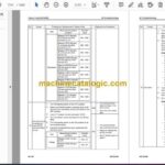
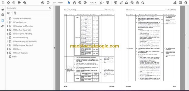
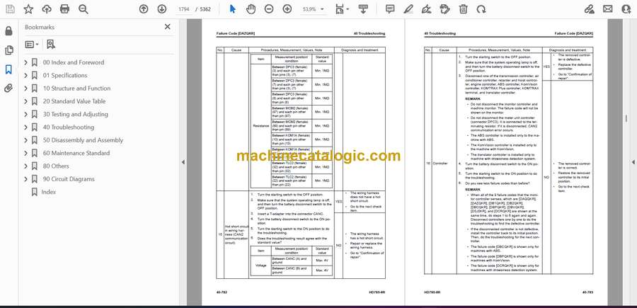