Komatsu HM460-6 Articulated Dump Truck Shop Manual (SEN07019-06) (SN 50001-UP)
The Komatsu HM460-6 Articulated Dump Truck is a production machine, moving heavy loads in quarries, big earthmoving jobs, and mine sites. People who reach for the Komatsu HM460-6 Articulated Dump Truck Shop Manual (SEN07019-06) are usually shop mechanics, field techs, or serious owner-operators. They’re trying to actually fix faults, rebuild components, and get to the “why did this fail?” level, not just do daily checks. If you’re chasing wiring faults, driveline issues, or hydraulic problems, this is the kind of book you’d expect to use.
What this manual helps you do
- Trace hydraulic and electrical faults using system layouts and step‑by‑step diagnostic procedures that these manuals usually provide.
- Check engine, transmission, and brake systems with guided test procedures so you don’t just throw parts at a problem.
- Follow teardown and reassembly sequences for major components on the truck, with the typical workshop-style instructions you see in a factory shop manual.
- Diagnose warning lights and abnormal behaviors by working through symptom-based troubleshooting trees that are normally included.
- Handle adjustments and post‑repair checks so the truck leaves the bay safe and behaving like it should, which is where most students struggle.
Who this is for
This shop manual is aimed at field technicians, dealership or fleet shop mechanics, and advanced trainees learning full repair procedures. If you only want basic operation, safety, and daily service points, you’re better off with the Operation and Maintenance Manual instead of this one.
FAQ
Q: Is this a PDF I can download and search or print?
A: Yes, it’s supplied as a PDF, so you can search terms and print specific sections for use in the shop.
Q: Is this deep enough for full rebuilds, or just basic service?
A: The Komatsu HM460-6 Articulated Dump Truck Shop Manual normally covers diagnostic procedures, disassembly/assembly, and adjustment work for workshop-level repairs.
Q: How do I know if it matches my exact HM460-6 truck?
A: Check your machine’s model and any serial information against the listing; this manual is written for the HM460-6 series, but you should always confirm it matches your specific build before buying.
If you’re repairing or diagnosing the HM460-6 at component level, this is what you want; if you just operate or schedule maintenance, you should keep looking.
📘 Show Index
Komatsu HM460-6 Articulated Dump Truck Shop Manual (SEN07019-06) (SN 50001-UP) Index:
- 00 Index and Foreword
- Index
- Foreword, Safety, Basic Information
- How to Read the Shop Manual
- Safety Notice for Operation
- Precautions to Prevent Fire
- Procedures If Fire Occurs
- Precautions for Disposing of Waste Materials
- Engine Technology to Conform Exhaust Gas Emission
- Precautions for DEF
- General Character and Precautions for Handling
- Precautions for Adding
- Precautions for Storage
- Precautions for Fire Hazard and Leakage
- Other Precautions
- Store DEF
- Precautions When You Handle Hydraulic Equipment
- Precautions When You Disconnect and Connect Pipings
- Precautions When You Handle Electrical Equipment
- Precautions When You Handle Fuel System Equipment
- Precautions When You Handle Intake System Equipment
- Practical Use of KOMTRAX
- Disconnect and Connect Push-Pull Type Coupler
- How to Disconnect and Connect Type 1 Push-Pull Type Coupler
- How to Disconnect and Connect Type 2 Push-Pull Type Coupler
- How to Disconnect and Connect Type 3 Push-Pull Type Coupler
- Precautions for Disconnection and Connection of Connectors
- How to Disconnect and Connect Deutsch Connector
- How to Disconnect and Connect Slide Lock Type Connector
- How to Disconnect and Connect Connector with Lock to Pull
- How to Disconnect and Connect Connector with Lock to Push
- How to Disconnect and Connect Connector with Housing to Rotate
- Standard Tightening Torque Table
- Conversion Table
- Abbreviation List
- 01 Specifications
- Table of Contents
- Specifications
- Specification Drawing
- Specification Drawing: HM460-6
- Specifications
- Weight Table
- Fuel, Coolant, Lubricant(For North America)
- How to Use Fuel, Coolant and Lubricants by Ambient Temperature
- Fuel, Coolant, and Lubricating Oil (For Europe)
- How to Use Fuel, Coolant and Lubricants by Ambient Temperature
- Fuel, Coolant, and Lubricating Oil (For Oceania)
- How to Use Fuel, Coolant and Lubricants by Ambient Temperature
- 10 Structure and Function
- Table of Contents
- Urea SCR System
- Layout Drawing of Urea SCR System
- Urea SCR System Diagram
- Function of Urea SCR System
- Function of DEF System
- Inducement Strategy
- Component Parts of Urea SCR System
- DEF Mixing Device
- SCR Assembly
- DEF Tank
- DEF Pump
- DEF Injector
- DEF Hose
- DEF Tank Heating Valve
- Boot-up System
- Layout Drawing of Boot-up System
- System Operating Lamp System
- System Diagram of System Operating Lamp System
- Function of Operation Lamp System
- Battery Disconnect Switch
- Function of Battery Disconnect Switch
- Preheating System
- System Diagram of Preheating System
- Function of Automatic Preheating System
- Operation of Automatic Preheating System
- Function of Manual Preheating System
- Operation of Manual Preheating System
- Starter Signal Unit System
- Starter Signal Unit System Diagram
- Function of Starter Signal Unit System
- Lamp Turn-On System
- Lamp Turn-On System Diagram
- Function of Lamp Turn-On System
- Engine System
- Layout Drawing of Engine System
- Function of Engine System
- Intake and Exhaust System Circuit Diagram
- Function of Intake and Exhaust System
- Engine Control System
- System Diagram of Engine Control
- Function of Engine Control System
- Operation of Engine Control System
- Automatic Idle Stop System
- Function of Automatic Idle Stop System
- Delayed Engine Shutdown System
- Function of Delayed Engine Shutdown System
- Component Parts of Engine System
- Fuel Tank
- Damper
- Turbocharger
- Turbo Bypass Valve
- Oil Mist Separator
- Exhaust Throttle Valve
- KDPF Assembly
- Air Cleaner
- Cooling System
- Layout Drawing of Cooling System
- Specifications of Cooling System
- Radiator Fan Control System
- Radiator Fan Control System Diagram
- Function of Radiator Fan Control System
- Aftercooler Fan Control System
- Aftercooler Fan Control System Diagram
- Function of Aftercooler Fan Control System
- Component Parts of Cooling System
- Radiator Fan Motor
- Aftercooler Fan Motor
- Hydraulic Oil Cooler Bypass Valve
- Control System
- Layout Drawing of Control System
- Retarder and Hoist Control System
- System Diagram of Retarder and Hoist Control System
- Machine Monitor System
- Machine Monitor System Diagram
- Function of Machine Monitor System
- Sub Monitor System
- Sub Monitor System Diagram
- Function of Sub Monitor System
- KomVision System
- Precautions for KomVision System
- Layout Drawing of KomVision System
- System Diagram of KomVision System
- Function of KomVision System
- Display Range of Bird’s Eye View Image
- Radio Sound System
- System Diagram of Radio Sound System
- Function of Radio Sound System
- KOMTRAX System
- System Diagram of KOMTRAX System
- Function of KOMTRAX System
- Payload Meter System
- Layout Drawing of Payload Meter System
- System Diagram of AUX Control System
- Function of AUX Control System
- Measurement Principle of Loading Mass
- Drowsiness Detection System
- Layout Drawing of Drowsiness Detection System
- System Diagram of Drowsiness Detection System
- Function of Drowsiness Detection System
- Operation of Drowsiness Detection System
- Component Parts of Control System
- Machine Monitor
- Sub Monitor
- Monitor Switch
- Keypad
- Rearview Camera and KomVision Camera
- Gateway Function Controller
- Communication Terminal
- Transmission Controller
- Retarder and Hoist Controller
- AUX Controller
- Monitor Controller
- KomVision Controller
- Starter Signal Unit
- CAN Terminating Resistor
- Engine Controller
- Drowsiness Detection Camera
- Driver Status Monitor
- Accelerator Pedal
- Gear Shift Lever
- Gear Speed Limit Selection/Shift Hold Lever
- Retarder Control Lever
- Fuel Feed Pump
- Fuel Feed Pump Switch
- Hydraulic System
- Layout Drawing of Hydraulic System
- Component Parts of Hydraulic System
- Hydraulic Tank
- Steering and Hoist Pump
- LS Valve
- PC Valve
- Power Train, Brake Cooling Duplex Pump
- Radiator Fan and Brake Charge Pump
- Valve Assembly (Dump EPC, Differential Lock, Accumulator Charge, and Parking Brake Solenoid)
- Hoist Valve
- Power Train System
- Layout Drawing of Power Train System
- Transmission Control System
- Transmission Control System Diagram
- Gear Shift Lever Positions and Automatic Gear Shift Range
- Gear Shift Control System
- Automatic Gear Shift Control of Gear Shift Control System
- Shift Hold System
- Function of Shift Hold System
- Direction Control System
- Rim Pull Limit Function for Overload Prevention of Direction Control System
- Komatsu Traction Control System (KTCS)
- Komatsu Traction Control System (KTCS) System Diagram
- Function of Komatsu Traction Control System (KTCS)
- Operation of Komatsu Traction Control System (KTCS) System Logic
- Travel Speed Limitation System
- System Diagram of Travel Speed Limitation System
- Function of Travel Speed Limitation System
- Operation of Travel Speed Limitation System
- Component Parts of Power Train System
- Drive Shaft
- Torque Converter and PTO
- Transmission
- Transmission Control Valve
- Lockup Clutch ECMV
- No.1, No.2, No.3, No.4, No.5, and No.6 Clutch ECMV
- Differential Lock Clutch ECMV
- Valve Assembly (Main Pressure Variable, Torque Converter Relief, Main Flow Rate Select)
- Power Train Scavenging Pump
- Axle
- Differential
- Final Drive
- Work Equipment System
- Work Equipment Control
- Layout Drawing of Work Equipment Control
- Function of Work Equipment Control
- Hoist Control
- Hoist Control System Diagram
- Function of Hoist Control
- Component Parts of Work Equipment System
- Steering System
- Layout Drawing of Steering System
- Function of Steering System
- Steering Column
- Structure of Steering Column
- Function of Steering Column
- Component Parts of Steering System
- Flow Amplifier Valve
- Steering Valve
- Steering Pump Selector Solenoid Valve
- Secondary Steering Pump
- Secondary Steering Motor
- Brake System
- Layout Drawing of Brake System
- Retarder Control
- Retarder Control System Diagram
- Function of Retarder Control
- Brake Performance, Allowable Max Travel Speed, and Gear Speed on Downhill
- ARSC System
- System Diagram of ARSC System
- Function of ARSC System
- Component Parts of Brake System
- Brake Circuit Accumulator
- Brake Valve
- Shut Off Solenoid Valve and Retarder Proportional Pressure Reducing Valve
- Slack Adjuster
- Brake
- Front Brake Cooling Relief Valve
- Center Brake Cooling Relief Valve
- Parking Brake
- Spring Cylinder
- Auto-Greasing System
- Layout Drawing of Auto-Greasing System
- Auto-Greasing System Diagram
- Specifications of Auto-Greasing System
- Function of Auto-Greasing System
- Auto-Greasing System
- Undercarriage and Frame
- Front Suspension
- Structure of Front Suspension
- Function of Front Suspension
- Center and Rear Suspensions
- Structure of Center and Rear Suspensions
- Function of Center Suspension
- Function of Rear Suspension
- Suspension Cylinder
- Structure of Suspension Cylinder
- Function of Suspension Cylinder
- Operation of Suspension Cylinder
- Oscillation Hitch
- Structure of Oscillation Hitch
- Function of Oscillation Hitch
- Tires
- Structure of Radial Tire
- Function of Radial Tire
- Work Equipment
- Structure of Work Equipment
- Function of Work Equipment
- CAB Related Parts
- Wiper System
- Layout Drawing of Wiper System
- Wiper System Diagram
- Function of Wiper System
- ROPS CAB
- Structure of ROPS CAB
- Function of ROPS CAB
- CAB Tilt
- CAB Mount
- Structure of CAB Mount
- Function of CAB Mount
- 20 Standard Value Table
- Table of Contents
- Standard Value Table for Engine
- Standard Value Table for Engine: HM460-6
- Standard Value Table for Machine
- Standard Value Table for Machine HM460-6
- Machine Posture and Procedures to Measure Performance
- 30 Testing and Adjusting
- Table of Contents
- Precautions Before Work
- Related Information on Testing and Adjusting
- Tools for Testing and Adjusting
- Sketch of Tools for Testing and Adjusting
- Engine and Cooling System
- Examine Engine Speed
- How to Examine Engine High Idle Speed
- How to Examine Engine Low Idle Speed
- How to Examine Engine Speed at Torque Converter Stall
- How to Examine Engine Speed When Torque Converter Lockup Function is on or off
- How to Examine Engine Speed at Transmission Upshift or Downshift
- How to Examine Engine Speed at Transmission Downshift Inhibit
- How to Examine Engine Speed When Overrun Prevention Function is on or off
- Examine Boost Pressure
- How to Examine Boost Pressure by SDT
- How to Examine Boost Pressure by Testing Tool
- Examine Exhaust Gas Temperature
- How to Examine Exhaust Air Temperature
- Examine Exhaust Gas Color
- How to Examine Exhaust Gas Color with Handy Smoke Checker
- How to Examine Exhaust Gas Color with Smoke Meter
- Examine and Adjust Valve Clearance
- How to Examine Valve Clearance
- How to Adjust Valve Clearance
- Examine Compression Pressure
- How to Examine Compression Pressure
- Examine Blowby Pressure
- How to Examine Blowby Pressure
- Examine Engine Oil Pressure
- How to Examine Engine Oil Pressure by SDT
- How to Examine Engine Oil Pressure by Testing Tool
- Examine Fuel Pressure
- How to Examine Fuel Pressure
- Examine Fuel Return Rate and Leakage
- How to Examine Fuel Return Rate and Leakage
- Bleed Air from Fuel System
- How to Bleed Air from Fuel System
- Examine Fuel Circuit for Leakage
- How to Examine Fuel System for Leakage
- Test Fuel Low Pressure Circuit Devices
- How to Examine Fuel Low Pressure Circuit Devices
- Handle Cylinder Cut-out Mode Operation
- Handle No-Injection Cranking Operation
- Examine KDPF, SCR and Muffler Stack for Looseness and Damage
- How to Examine KDPF, SCR and Muffler Stack for Looseness and Damage
- Examine Installation of Cylinder Head Cover and Manifolds
- How to Examine Installed Condition of Cylinder Head covers and Manifolds
- Examine Engine Piping for Damage and Looseness
- How to Examine Engine Piping for Damage and Looseness
- Clean Fuel Doser
- Write Injector Compensation Value to Engine Controller
- How to Write Injector Compensation Value to Engine Controller
- Examine SCR Related Function
- Examine DEF Pump Raised Pressure
- Examine Injection Volume from DEF Injector
- Examine DEF Line Heater Relay 1
- Examine DEF Line Heater Relay 2
- Examine DEF Pump Heater Relay
- Examine DEF Tank Heater Valve
- Examine SCR Denitration Efficiency
- Clean DEF Tank
- Clean DEF Pump
- Radiator Fan Speed Test
- How to Examine Radiator Fan Speed
- Power Train
- Examine Power Train Oil Pressure
- How to Examine Power Train Main Relief Pressure by SDT
- How to Examine Power Train Main Relief Pressure by Testing Tool
- How to Examine Main Flow Selector Valve Inlet Pressure by SDT
- How to Examine Main Flow Selector Valve Inlet Pressure by Machine Monitor
- How to Examine Torque Converter Inlet Pressure by SDT
- How to Examine Torque Converter Inlet Pressure by Testing Tool
- How to Examine Outlet Pressure of Torque Converter
- How to Examine Operating Pressure of Torque Converter Lockup Clutch
- How to Examine Transmission No.1 Clutch Operating Pressure
- How to Examine Transmission No.2 Clutch Operating Pressure
- How to Examine Transmission No.3 Clutch Operating Pressure
- How to Examine Transmission No.4 Clutch Operating Pressure
- How to Examine Transmission No.5 Clutch Operating Pressure
- How to Examine Transmission No.6 Clutch Operating Pressure
- How to Examine Inter-Axle Differential Lock Clutch Operating Pressure
- How to Examine Right and Left Differential Lock Operating Pressure
- Adjust Transmission Speed Sensor
- How to Adjust Transmission Speed Sensor
- Adjust Transmission Controller
- How to Adjust Transmission Controller
- Move Machine Which Has a Trouble in Electrical System
- How to Move Machine Which Has a Trouble in Engine Control System
- How to move machine Which Has a Trouble in Transmission Control System
- Move Machine Which Has a Trouble in Traction Control System (KTCS)
- How to Move Machine with Secondary KTCS Operation Connector
- Bleed Air from Differential Lock Circuit
- How to Bleed Air from Differential Lock Circuit
- Steering System
- Examine and Adjust Steering Circuit Oil Pressure
- How to Examine Steering Circuit Oil Pressure by SDT
- How to Examine Steering Circuit Pressure with Test Tools
- How to Adjust Steering Circuit Oil Pressure
- Bleed Air from Steering Cylinder Circuit
- How to Bleed Air from Steering Cylinder Circuit
- Brake System
- Examine Brake Oil Pressure
- How to Examine Brake Oil Pressure
- Examine Nitrogen Gas Pressure in Brake Accumulator and Charge Gas
- How to Examine Accumulator Nitrogen Gas Pressure
- How to Charge Accumulator Nitrogen Gas for Brake
- Release Remained Pressure in Brake Accumulator Circuit
- How to Release Remained Pressure in Brake Accumulator Circuit
- Bleed Air from Brake Circuit
- How to Bleed Air from Brake Circuit
- Examine Brake Performance
- Examine Wear of Wheel Brake Disc
- How to Examine Wear of Wheel Brake Disc
- Release Parking Brake Manually
- How to Release Parking Brake Manually
- Examine and Adjust Wear of Parking Brake Pad
- How to Examine Wear of Parking Brake Pad
- How to Adjust Clearance of Parking Brake Pad
- How to Do Contact Alignment of Parking Brake Pad
- Contact Alignment of Parking Brake Pad
- Hydraulic System
- Examine and Adjust Suspension Cylinder
- How to Examine Suspension Cylinder
- How to Adjust Suspension Cylinder
- Examine and Adjust Dump Circuit Oil Pressure
- How to Examine Dump Circuit Oil Pressure
- How to Adjust Dump Circuit Oil Pressure
- Bleed Air from Hoist Circuit
- How to Bleed Air from Hoist Cylinder
- How to Bleed Air from Pump Circuit
- Work Equipment
- Examine and Adjust Dump Body Positioner Sensor
- How to Examine Dump Body Positioner Sensor
- How to Adjust Dump Body Positioner Sensor
- Examine and Adjust Dump Body Mount
- How to Examine Dump Body Mount
- How to Adjust Dump Body Mount
- CAB Related Parts
- CAB Tilt Up
- How to Tilt Up Cab
- How to Tilt Down Cab
- Adjust Play of Operator Seat
- How to Adjust Play of Operator Seat
- Adjust Adjustment Noise of Operator Seat
- How to Eliminate Sliding Noise of Operator Seat
- How to Eliminate Tilting Noise of Operator Seat
- Electrical System
- Set and Adjust Each Equipment
- Adjustment by S-PRIT
- Adjustment Method by S-PRIT
- How to Connect by Wired LAN
- Set and Operate Machine Monitor
- Set and Operate by SDT
- Prepare for Transmission ECMV Current Adjustment
- How to Adjust Transmission ECMV Current
- How to Set and Reset Transmission Initial Learning
- How to Do System Check of KTCS (Komatsu Traction Control System)
- Connect SDT
- How to See Monitoring
- How to See Pre-Defined Monitoring
- Abnormality Record Menu
- How to Operate Maintenance
- Default Setting Menu
- Adjustment Menu
- Testing Menu
- Other Menu
- Menu for Engine
- How to Start Up KOMTRAX System
- How to Stop Use of KOMTRAX System
- Adjust Optical Axis of Head Lamp
- How to Adjust Optical Axis of Head Lamp
- Handle Voltage Circuit of Engine Controller
- Handle Battery Disconnect Switch
- Examine Diodes
- How to Examine Diodes by Digital Tester
- How to Examine Diodes by Analog Tester
- Pm Clinic
- Pm Clinic Service
- Pm Clinic Check Sheet: HM460-6
- 40 Troubleshooting
- Table of Contents
- Precautions Before Work
- Related Information for Troubleshooting
- Precautions for Troubleshooting
- Sequence of Events in Troubleshooting
- General Troubleshooting Points
- Troubleshooting Points for Urea SCR System
- Engine Controller Shutdown
- “Loaded Diagnostics Operation To Clear Failure Code” and “Loaded Diagnostics Operation To Confirm Failure Correction”on Troubleshooting
- Function to Clear Failure Code
- Select Failure Code to Be Repaired
- Table of Failure Codes that is Applied to Inducement
- Inspection Before Troubleshooting
- Inspection Procedure Before Troubleshooting
- Test in Accordance with Testing Procedure
- How to Examine Fuel Level and Add Fuel
- How to Drain Water and Sediment from Fuel Tank
- How to Examine DEF Level and Add DEF
- How to Replace Fuel Prefilter Cartridge
- How to Replace Fuel Main Filter Cartridge
- How to Examine Oil Level in Engine Oil Pan, Add Oil
- How to Examine Coolant Level, Add Coolant
- Examine, Clean and Replace Air Cleaner
- How to Examine Oil Level in Hydraulic Oil Tank, Add Oil
- How to Replace Hydraulic Oil Filter Element
- How to Examine Oil Level in Transmission Case, Add Oil
- How to Examine Oil Level in Front Differential Case and Add Oil
- How to Examine Oil Level in Final Drive Case, Add Oil
- Bleed Air from Fuel System
- Bleed Air from Hydraulic System
- How to Examine Electrical Components
- Preparation for Troubleshooting of Electrical System
- Preparation for Troubleshooting of Machine Monitor
- Preparation for Troubleshooting of Transmission Controller
- Preparation for Troubleshooting of Retarder and Hoist Controller
- Preparation for Troubleshooting of Monitor Controller
- Preparation for Troubleshooting of AUX Controller
- Preparation for Troubleshooting of Gateway Function Controller
- Preparation for Troubleshooting of Engine Controller
- How to Disconnect and Connect Connector with a Special Lock
- Inspection Procedure of Electrical System
- How to Examine Fuse
- How to Examine Fusible Link
- How to Examine Diodes
- How to Examine Relay
- How to Examine Switch
- How to Examine Sensor
- How to Examine When Sensor Power Supply is Defective
- How to Examine Solenoid and Actuation Device
- How to Examine Actuator
- Examine Wiring Harness
- How to Examine CAN Communication
- How to Examine Resistance
- How to Examine Power Supply to Controller
- Procedure for Troubleshooting
- Symptom and Troubleshooting Numbers
- Information Shown in Troubleshooting
- Connector List and Layout
- Connector Layout (1)
- Connector Layout (2)
- Connector Layout (3)
- Connector Layout (4)
- Connector Layout (5)
- Connector Layout (6)
- Connector Layout (7)
- Connector Layout (8)
- Connector Layout (9)
- Connector Layout (10)
- Connector Contact Connection Table
- T-Branch Box and T-Branch Adapter Table
- Fuse Location Table
- Precautions When You Clean and Replace KDPF (SF and KDOC)
- Prepare Troubleshoot Machine Monitor
- Prepare Short Circuit Electrical Connector (For Failure Codes [CA1883], [CA3135], and [CA5715])
- Failure Code Table
- Troubleshooting by Failure Code (Display of Code)
- Failure Code [1500L0]
- Failure Code [1572KA]
- Failure Code [1572LC]
- Failure Code [15B0NX]
- Failure Code [15SJMA]
- Failure Code [15SKMA]
- Failure Code [16A0MW]
- Failure Code [16B0MW]
- Failure Code [16C0MW]
- Failure Code [16D0MW]
- Failure Code [16E0MW]
- Failure Code [16F0MW]
- Failure Code [2A60MW]
- Failure Code [2B60MW]
- Failure Code [2F00KM]
- Failure Code [2G42ZG]
- Failure Code [2G43ZG]
- Failure Code [2H10L8]
- Failure Code [8761KX]
- Failure Code [879AKA]
- Failure Code [879AKB]
- Failure Code [879BKA]
- Failure Code [879BKB]
- Failure Code [879CKA]
- Failure Code [879CKB]
- Failure Code [879EMC]
- Failure Code [879FMC]
- Failure Code [879GKX]
- Failure Code [989800]
- Failure Code [989D00]
- Failure Code [989L00]
- Failure Code [989M00]
- Failure Code [989N00]
- Failure Code [989X00]
- Failure Code [989Y00]
- Failure Code [989YR2]
- Failure Code [A1U0N3]
- Failure Code [A1U0N4]
- Failure Code [A6LEKA]
- Failure Code [A6LEKY]
- Failure Code [A6LEKZ]
- Failure Code [A6LEL3]
- Failure Code [A6LFKA]
- Failure Code [A6LFKY]
- Failure Code [A6LFKZ]
- Failure Code [A6LFL3]
- Failure Code [AA10NX]
- Failure Code [AB00KE]
- Failure Code [AB00KY]
- Failure Code [AQ10MB]
- Failure Code [AQ10N3]
- Failure Code [AS00R2]
- Failure Code [AS00R3]
- Failure Code [AS00R4]
- Failure Code [AS00R5]
- Failure Code [AS00R6]
- Failure Code [AS00ZK]
- Failure Code [AS10KM]
- Failure Code [AS10NR]
- Failure Code [AS10NT]
- Failure Code [B@BAZG]
- Failure Code [B@BAZK]
- Failure Code [B@BCNS]
- Failure Code [B@BCQA]
- Failure Code [B@BCZK]
- Failure Code [B@C6NS]
- Failure Code [B@C8NS]
- Failure Code [B@CENS]
- Failure Code [B@JANS]
- Failure Code [C12643]
- Failure Code [C12644]
- Failure Code [C14254]
- Failure Code [C14481]
- Failure Code [CA122]
- Failure Code [CA123]
- Failure Code [CA135]
- Failure Code [CA141]
- Failure Code [CA144]
- Failure Code [CA145]
- Failure Code [CA153]
- Failure Code [CA154]
- Failure Code [CA187]
- Failure Code [CA221]
- Failure Code [CA222]
- Failure Code [CA227]
- Failure Code [CA234]
- Failure Code [CA238]
- Failure Code [CA239]
- Failure Code [CA249]
- Failure Code [CA256]
- Failure Code [CA295]
- Loaded Diagnostics Operation to Confirm Failure Correction
- Failure Code [CA322]
- Failure Code [CA323]
- Failure Code [CA324]
- Failure Code [CA325]
- Failure Code [CA331]
- Failure Code [CA332]
- Failure Code [CA343]
- Failure Code [CA351]
- Failure Code [CA352]
- Failure Code [CA386]
- Failure Code [CA431]
- Failure Code [CA432]
- Failure Code [CA449]
- Failure Code [CA451]
- Failure Code [CA452]
- Failure Code [CA515]
- Failure Code [CA516]
- Failure Code [CA553]
- Failure Code [CA555]
- Failure Code [CA556]
- Failure Code [CA559]
- Failure Code [CA584]
- Failure Code [CA585]
- Failure Code [CA595]
- Failure Code [CA687]
- Failure Code [CA689]
- Function of NE (Crankshaft) Speed Sensor
- Failure Code [CA691]
- Failure Code [CA692]
- Failure Code [CA697]
- Failure Code [CA698]
- Failure Code [CA731]
- Failure Code [CA741]
- Failure Code [CA742]
- Failure Code [CA743]
- Loaded Diagnostics Operation to Confirm Failure Correction
- Failure Code [CA778]
- Failure Code [CA1117]
- Failure Code [CA1358]
- Failure Code [CA1359]
- Failure Code [CA1669]
- Failure Code [CA1673]
- Failure Code [CA1677]
- Failure Code [CA1678]
- Failure Code [CA1682]
- Loaded Diagnostics Operation to Clear Failure Code
- Failure Code [CA1686]
- Failure Code [CA1695]
- Failure Code [CA1696]
- Failure Code [CA1713]
- Loaded Diagnostics Operation to Confirm Failure Correction
- Failure Code [CA1714]
- Failure Code [CA1715]
- Failure Code [CA1776]
- Failure Code [CA1777]
- Failure Code [CA1843]
- Failure Code [CA1844]
- Failure Code [CA1879]
- Failure Code [CA1881]
- Failure Code [CA1883]
- Clean KDPF Differential Pressure Sensor and Tube
- Loaded Diagnostics Operation to Clear Failure Code
- Failure Code [CA1885]
- Loaded Diagnostics Operation to Confirm Failure Correction
- Failure Code [CA1887]
- Loaded Diagnostics Operation to Confirm Failure Correction
- Failure Code [CA1921]
- Failure Code [CA1922]
- Failure Code [CA1923]
- Failure Code [CA1924]
- Diagram Related to Fuel Doser
- Failure Code [CA1925]
- Loaded Diagnostics Operation to Clear Failure Code
- Diagram Related to Fuel Doser
- Failure Code [CA1927]
- Failure Code [CA1928]
- Failure Code [CA1942]
- Failure Code [CA1963]
- Loaded Diagnostics Operation to Clear Failure Code
- Diagram Related to Fuel Doser
- Fuel System Circuit Diagram
- Failure Code [CA1977]
- Loaded Diagnostics Operation to Clear Failure Code
- Failure Code [CA2185]
- Failure Code [CA2186]
- Failure Code [CA2249]
- Failure Code [CA2265]
- Failure Code [CA2266]
- Failure Code [CA2638]
- Failure Code [CA2639]
- Failure Code [CA2732]
- Failure Code [CA2733]
- Failure Code [CA2741]
- Loaded Diagnostics Operation to Clear Failure Code
- Diagram Related to Fuel Doser
- Failure Code [CA2765]
- Failure Code [CA2771]
- Failure Code [CA2878]
- Loaded Diagnostics Operation to Clear Failure Code
- Diagram Related to Fuel Doser
- Failure Code [CA2881]
- Loaded Diagnostics Operation to Clear Failure Code
- Diagram Related to Fuel Doser
- Fuel System Circuit Diagram
- Failure Code [CA2973]
- Loaded Diagnostics Operation to Confirm Failure Correction
- Failure Code [CA2976]
- Failure Code [CA3133]
- Failure Code [CA3134]
- Failure Code [CA3135]
- Loaded Diagnostics Operation to Clear Failure Code
- Failure Code [CA3146]
- Failure Code [CA3147]
- Failure Code [CA3148]
- Loaded Diagnostics Operation to Confirm Failure Correction
- Failure Code [CA3151]
- Loaded Diagnostics Operation to Confirm Failure Correction
- Failure Code [CA3165]
- Loaded Diagnostics Operation to Confirm Failure Correction
- Failure Code [CA3167]
- How to Reset Fuel Doser Information
- Diagram Related to Fuel Doser
- Failure Code [CA3232]
- Failure Code [CA3235]
- Loaded Diagnostics Operation to Confirm Failure Correction
- Failure Code [CA3239]
- Failure Code [CA3241]
- Failure Code [CA3251]
- Loaded Diagnostics Operation to Clear Failure Code
- Failure Code [CA3253]
- Loaded Diagnostics Operation to Clear Failure Code
- Failure Code [CA3255]
- Loaded Diagnostics Operation to Clear Failure Code
- Failure Code [CA3311]
- Loaded Diagnostics Operation to Confirm Failure Correction
- Failure Code [CA3312]
- Loaded Diagnostics Operation to Confirm Failure Correction
- Failure Code [CA3313]
- Failure Code [CA3314]
- Failure Code [CA3315]
- Loaded Diagnostics Operation to Confirm Failure Correction
- Failure Code [CA3316]
- Failure Code [CA3317]
- Failure Code [CA3318]
- Loaded Diagnostics Operation to Confirm Failure Correction
- Failure Code [CA3319]
- Failure Code [CA3321]
- Failure Code [CA3322]
- Loaded Diagnostics Operation to Confirm Failure Correction
- Failure Code [CA3375]
- Failure Code [CA3376]
- Failure Code [CA3419]
- Failure Code [CA3421]
- Failure Code [CA3463]
- Failure Code [CA3464]
- Failure Code [CA3468]
- Failure Code [CA3471]
- Failure Code [CA3472]
- Failure Code [CA3473]
- Failure Code [CA3497]
- Failure Code [CA3498]
- Failure Code [CA3545]
- Loaded Diagnostics Operation to Confirm Failure Correction
- Failure Code [CA3547]
- Failure Code [CA3558]
- Failure Code [CA3559]
- Failure Code [CA3567]
- Loaded Diagnostics Operation to Clear Failure Code
- Failure Code [CA3568]
- Loaded Diagnostics Operation to Clear Failure Code
- Failure Code [CA3571]
- Failure Code [CA3572]
- Failure Code [CA3574]
- Loaded Diagnostics Operation to Clear Failure Code
- Failure Code [CA3575]
- Loaded Diagnostics Operation to Clear Failure Code
- Failure Code [CA3577]
- Failure Code [CA3578]
- Failure Code [CA3583]
- Loaded Diagnostics Operation to Confirm Failure Correction
- Failure Code [CA3596]
- Loaded Diagnostics Operation to Clear Failure Code
- Failure Code [CA3649]
- Loaded Diagnostics Operation to Confirm Failure Correction
- Failure Code [CA3681]
- Loaded Diagnostics Operation to Confirm Failure Correction
- Failure Code [CA3682]
- Loaded Diagnostics Operation to Confirm Failure Correction
- Failure Code [CA3725]
- Loaded Diagnostics Operation to Confirm Failure Correction
- Failure Code [CA3748]
- Loaded Diagnostics Operation to Confirm Failure Correction
- Failure Code [CA3866]
- Loaded Diagnostics Operation to Clear Failure Code
- Failure Code [CA3868]
- Failure Code [CA4151]
- Failure Code [CA4155]
- Failure Code [CA4156]
- Failure Code [CA4157]
- Loaded Diagnostics Operation to Clear Failure Code
- Failure Code [CA4158]
- Failure Code [CA4161]
- Failure Code [CA4162]
- Failure Code [CA4163]
- Loaded Diagnostics Operation to Confirm Failure Correction
- Failure Code [CA4168]
- Loaded Diagnostics Operation to Confirm Failure Correction
- Failure Code [CA4169]
- Loaded Diagnostics Operation to Confirm Failure Correction
- Failure Code [CA4171]
- Loaded Diagnostics Operation to Confirm Failure Correction
- Failure Code [CA4249]
- Loaded Diagnostics Operation to Confirm Failure Correction
- Failure Code [CA4251]
- Loaded Diagnostics Operation to Confirm Failure Correction
- Failure Code [CA4259]
- Failure Code [CA4264]
- Failure Code [CA4266]
- Failure Code [CA4267]
- Failure Code [CA4277]
- Loaded Diagnostics Operation to Clear Failure Code
- Failure Code [CA4459]
- Failure Code [CA4461]
- Failure Code [CA4731]
- Failure Code [CA4739]
- Failure Code [CA4768]
- Loaded Diagnostics Operation to Clear Failure Code
- Failure Code [CA4769]
- Loaded Diagnostics Operation to Clear Failure Code
- Failure Code [CA4842]
- Loaded Diagnostics Operation to Clear Failure Code
- Failure Code [CA5115]
- Failure Code [CA5179]
- Failure Code [CA5181]
- Failure Code [CA5271]
- Failure Code [CA5272]
- Failure Code [CA5383]
- Failure Code [CA5631]
- Failure Code [CA5632]
- Failure Code [CA5655]
- Loaded Diagnostics Operation to Confirm Failure Correction
- Failure Code [CA5689]
- Loaded Diagnostics Operation to Confirm Failure Correction
- Failure Code [CA5715]
- Loaded Diagnostics Operation to Clear Failure Code
- Failure Code [CA5741]
- Failure Code [CA5838]
- Loaded Diagnostics Operation to Confirm Failure Correction
- Failure Code [CA5864]
- Failure Code [CA5865]
- Failure Code [CA5938]
- Failure Code [CA6256]
- Failure Code [CA6257]
- Failure Code [CA6266]
- Loaded Diagnostics Operation to Confirm Failure Correction
- Failure Code [CA6475]
- Loaded Diagnostics Operation to Confirm Failure Correction
- Failure Code [CA6476]
- Loaded Diagnostics Operation to Confirm Failure Correction
- Failure Code [CA6477]
- Failure Code [CA6478]
- Failure Code [CA6479]
- Failure Code [CA6481]
- Failure Code [CA6512]
- Failure Code [CA6524]
- Failure Code [CA6525]
- Failure Code [CA6526]
- Failure Code [CA6537]
- Failure Code [CA6556]
- Failure Code [CA6557]
- Failure Code [CA6595]
- Failure Code [CA6619]
- Loaded Diagnostics Operation to Confirm Failure Correction
- Failure Code [CA6654]
- Failure Code [CA6726]
- Loaded Diagnostics Operation to Clear Failure Code
- Failure Code [CA6887]
- Failure Code [CA6891]
- Failure Code [CA7326]
- Failure Code [CA7453]
- Loaded Diagnostics Operation to Clear Failure Code
- Failure Code [CA7454]
- Loaded Diagnostics Operation to Clear Failure Code
- Failure Code [CA7681]
- Failure Code [CA7797]
- Failure Code [CA7798]
- Failure Code [CA7822]
- Failure Code [CA7869]
- Failure Code [CA8453]
- Failure Code [CA8465]
- Failure Code [CA8466]
- Failure Code [CA8526]
- Loaded Diagnostics Operation to Clear Failure Code
- Failure Code [D014KA]
- Failure Code [D01QKR]
- Failure Code [D101KA]
- Failure Code [D101KB]
- Failure Code [D101KY]
- Failure Code [D102KA]
- Failure Code [D102KB]
- Failure Code [D102KY]
- Failure Code [D141KA]
- Failure Code [D141KB]
- Failure Code [D141KY]
- Failure Code [D150KB]
- Failure Code [D150KZ]
- Failure Code [D151KB]
- Failure Code [D151KZ]
- Failure Code [D164KY]
- Failure Code [D164KZ]
- Failure Code [D16AKA]
- Failure Code [D16AKB]
- Failure Code [D16AKY]
- Failure Code [D19HKZ]
- Failure Code [D19JKZ]
- Failure Code [D1FBKB]
- Failure Code [D1FCKA]
- Failure Code [D1FCKB]
- Failure Code [D1FCKY]
- Failure Code [D1FDKA]
- Failure Code [D1FDKB]
- Failure Code [D1FDKY]
- Failure Code [D1FEKA]
- Failure Code [D1FEKB]
- Failure Code [D1FEKY]
- Failure Code [D1TFKA]
- Failure Code [D1TFKB]
- Failure Code [D1TFKY]
- Failure Code [D1THKA]
- Failure Code [D1THKB]
- Failure Code [D1THKY]
- Failure Code [D1TJKA]
- Failure Code [D1TJKB]
- Failure Code [D1TJKY]
- Failure Code [D201QC]
- Failure Code [D524KL]
- Failure Code [D524KU]
- Failure Code [D525KL]
- Failure Code [D525KN]
- Failure Code [D526KN]
- Failure Code [D527KN]
- Failure Code [D528KN]
- Failure Code [D528KP]
- Failure Code [D529KX]
- Failure Code [D52DKN]
- Failure Code [D52DKP]
- Failure Code [D52EKN]
- Failure Code [D52FKN]
- Failure Code [D52GKN]
- Failure Code [D52HKN]
- Failure Code [D52JKN]
- Failure Code [D52KKN]
- Failure Code [D52LKN]
- Failure Code [D52MKX]
- Failure Code [D52NKX]
- Failure Code [D52PKX]
- Failure Code [D52QKR]
- Failure Code [D52TKX]
- Failure Code [D52UKX]
- Failure Code [D52VKN]
- Failure Code [D52WKL]
- Failure Code [D52WKN]
- Failure Code [D52WKU]
- Failure Code [D52XKB]
- Failure Code [D52YKB]
- Failure Code [D52ZKR]
- Failure Code [D52ZKT]
- Failure Code [D52ZLA]
- Failure Code [D5ZHL6]
- Failure Code [D811MC]
- Failure Code [D862KA]
- Failure Code [D8ALKA]
- Failure Code [D8ALKB]
- Failure Code [D8G1KT]
- Failure Code [D8GCKR]
- Failure Code [D8GDKA]
- Failure Code [D8GDKB]
- Failure Code [D8GPKR]
- Failure Code [D8N1MA]
- Failure Code [D8N2MA]
- Failure Code [D8N3MA]
- Failure Code [D9DMKR]
- Failure Code [DAF0MB]
- Failure Code [DAF0MC]
- Failure Code [DAF3KK]
- Failure Code [DAF9KQ]
- Failure Code [DAFDKB]
- Failure Code [DAFEKB]
- Failure Code [DAFEKY]
- Failure Code [DAFGMC]
- Failure Code [DAFLKA]
- Failure Code [DAFLKB]
- Failure Code [DAFMKR]
- Failure Code [DAFPKR]
- Failure Code [DAFRMA]
- Failure Code [DAFUKA]
- Failure Code [DAFUKB]
- Failure Code [DAFUKY]
- Failure Code [DAQ0KK]
- Failure Code [DAQ0KT]
- Failure Code [DAQ0MC]
- Failure Code [DAQ1KA]
- Failure Code [DAQ2KK]
- Failure Code [DAQ2KT]
- Failure Code [DAQ5KX]
- Failure Code [DAQ6KX]
- Failure Code [DAQ7KX]
- Failure Code [DAQ9KQ]
- Failure Code [DAQLKA]
- Failure Code [DAQLKB]
- Failure Code [DAQMKR]
- Failure Code [DAQPKR]
- Failure Code [DAQRMA]
- Failure Code [DAQSKR]
- Failure Code [DAQV00]
- Failure Code [DAQW00]
- Failure Code [DASRKR]
- Failure Code [DAZ9KQ]
- Failure Code [DAZQKR]
- Failure Code [DB10KT]
- Failure Code [DB10MC]
- Failure Code [DB11KA]
- Failure Code [DB12KK]
- Failure Code [DB12KT]
- Failure Code [DB13KK]
- Failure Code [DB19KQ]
- Failure Code [DB1LKA]
- Failure Code [DB1LKB]
- Failure Code [DB1MKR]
- Failure Code [DB1PKR]
- Failure Code [DB1QMA]
- Failure Code [DB1SKR]
- Failure Code [DB1Z00]
- Failure Code [DB1ZKM]
- Failure Code [DB2RKR]
- Failure Code [DBP0KM]
- Failure Code [DBP0KT]
- Failure Code [DBPRKR]
- Failure Code [DBPWKR]
- Failure Code [DBRTKA]
- Failure Code [DBRTKB]
- Failure Code [DBRTKY]
- Failure Code [DBTLKB]
- Failure Code [DBTMKB]
- Failure Code [DCV0KA]
- Failure Code [DCV0KQ]
- Failure Code [DCV0KT]
- Failure Code [DCV0MA]
- Failure Code [DCV0MC]
- Failure Code [DCV2KK]
- Failure Code [DCV3KK]
- Failure Code [DCV4KB]
- Failure Code [DCV5KB]
- Failure Code [DCVLKA]
- Failure Code [DCVLKB]
- Failure Code [DCVMKR]
- Failure Code [DCVPKR]
- Failure Code [DDAAL6]
- Failure Code [DDB6L4]
- Failure Code [DDD7KX]
- Failure Code [DDNRL4]
- Failure Code [DDUAKR]
- Failure Code [DDUBKR]
- Failure Code [DDUCKR]
- Failure Code [DDUEKA]
- Failure Code [DDUFKA]
- Failure Code [DDUGKA]
- Failure Code [DDUHKA]
- Failure Code [DDUJKA]
- Failure Code [DDUKKA]
- Failure Code [DDWNKX]
- Failure Code [DDWPKY]
- Failure Code [DDWQKX]
- Failure Code [DF11KX]
- Failure Code [DF11L3]
- Failure Code [DF11L8]
- Failure Code [DF12KX]
- Failure Code [DF12L3]
- Failure Code [DF61KX]
- Failure Code [DF61L3]
- Failure Code [DF61L8]
- Failure Code [DF62KX]
- Failure Code [DF62L3]
- Failure Code [DF63K4]
- Failure Code [DF63KX]
- Failure Code [DF63L8]
- Failure Code [DF64K4]
- Failure Code [DF64KX]
- Failure Code [DGF1KX]
- Failure Code [DGR3KB]
- Failure Code [DGR3L8]
- Failure Code [DGR4KB]
- Failure Code [DGR4L8]
- Failure Code [DGR6KB]
- Failure Code [DGR6L8]
- Failure Code [DGT1KX]
- Failure Code [DHP4KY]
- Failure Code [DHP4KZ]
- Failure Code [DHP5KY]
- Failure Code [DHP5KZ]
- Failure Code [DHP6KY]
- Failure Code [DHP6KZ]
- Failure Code [DHP7KY]
- Failure Code [DHP7KZ]
- Failure Code [DHQ2KX]
- Failure Code [DHQ4KX]
- Failure Code [DHT5KX]
- Failure Code [DHT5L6]
- Failure Code [DHT8KX]
- Failure Code [DHT8ZG]
- Failure Code [DHU2KX]
- Failure Code [DHU3KX]
- Failure Code [DHUAKX]
- Failure Code [DHUBKX]
- Failure Code [DHUCKX]
- Failure Code [DHUDKX]
- Failure Code [DHUEKX]
- Failure Code [DHUGKX]
- Failure Code [DHUKKX]
- Failure Code [DHUQKX]
- Failure Code [DHURKX]
- Failure Code [DJF1KA]
- Failure Code [DK30KX]
- Failure Code [DK51L5]
- Failure Code [DK52KX]
- Failure Code [DK53L8]
- Failure Code [DK54KX]
- Failure Code [DK80KR]
- Failure Code [DK80KT]
- Failure Code [DK83KR]
- Failure Code [DK83KT]
- Failure Code [DLF1KA]
- Failure Code [DLF1LC]
- Failure Code [DLF2KA]
- Failure Code [DLF2LC]
- Failure Code [DLF4KA]
- Failure Code [DLF4KX]
- Failure Code [DLF4LC]
- Failure Code [DLF6LC]
- Failure Code [DLF7LC]
- Failure Code [DLFDLC]
- Failure Code [DLFELC]
- Failure Code [DLFFLC]
- Failure Code [DLFGLC]
- Failure Code [DLM3KA]
- Failure Code [DLM3LC]
- Failure Code [DLM3MB]
- Failure Code [DLT3KX]
- Failure Code [DLT3LC]
- Failure Code [DLT4KX]
- Failure Code [DPQ2KR]
- Failure Code [DR12KA]
- Failure Code [DR12KB]
- Failure Code [DR12KK]
- Failure Code [DR12KR]
- Failure Code [DR12KY]
- Failure Code [DU6AKB]
- Failure Code [DU6AKY]
- Failure Code [DU6BKA]
- Failure Code [DU6BKB]
- Failure Code [DU6BKY]
- Failure Code [DU6CKA]
- Failure Code [DU6CKB]
- Failure Code [DU6CKY]
- Failure Code [DU6DKA]
- Failure Code [DU6DKB]
- Failure Code [DU6DKY]
- Failure Code [DUMBKA]
- Failure Code [DUMBKB]
- Failure Code [DW2AKA]
- Failure Code [DW2AKB]
- Failure Code [DW2AKY]
- Failure Code [DW2AL1]
- Failure Code [DW2ALH]
- Failure Code [DW2BKA]
- Failure Code [DW2BKB]
- Failure Code [DW2BKY]
- Failure Code [DW2BL1]
- Failure Code [DW2BLH]
- Failure Code [DW4BK4]
- Failure Code [DW4BKA]
- Failure Code [DW4BKB]
- Failure Code [DW4BKY]
- Failure Code [DW4BMA]
- Failure Code [DW5TKT]
- Failure Code [DW5TKY]
- Failure Code [DW73KA]
- Failure Code [DW73KB]
- Failure Code [DW73KY]
- Failure Code [DW78KZ]
- Failure Code [DW7BKB]
- Failure Code [DW7BKY]
- Failure Code [DW7BKZ]
- Failure Code [DW7NKZ]
- Failure Code [DWNJKZ]
- Failure Code [DWNKKZ]
- Failure Code [DX12L8]
- Failure Code [DX13KA]
- Failure Code [DX13KB]
- Failure Code [DX13KY]
- Failure Code [DX16KA]
- Failure Code [DX16KB]
- Failure Code [DX16KY]
- Failure Code [DX1AK4]
- Failure Code [DX1AKB]
- Failure Code [DX1AKY]
- Failure Code [DX1AKZ]
- Failure Code [DX1AMA]
- Failure Code [DX30K4]
- Failure Code [DX30KA]
- Failure Code [DX30KB]
- Failure Code [DX30KY]
- Failure Code [DX30MA]
- Failure Code [DX31K4]
- Failure Code [DX31KA]
- Failure Code [DX31KB]
- Failure Code [DX31KY]
- Failure Code [DX31MA]
- Failure Code [DX32K4]
- Failure Code [DX32KA]
- Failure Code [DX32KB]
- Failure Code [DX32KY]
- Failure Code [DX32MA]
- Failure Code [DX33K4]
- Failure Code [DX33KA]
- Failure Code [DX33KB]
- Failure Code [DX33KY]
- Failure Code [DX33MA]
- Failure Code [DX3AKT]
- Failure Code [DX3AKY]
- Failure Code [DX3BKT]
- Failure Code [DX3BKY]
- Failure Code [DX3CKT]
- Failure Code [DX3CKY]
- Failure Code [DX3DKT]
- Failure Code [DX3DKY]
- Failure Code [DXD1KA]
- Failure Code [DXD1KB]
- Failure Code [DXD1KY]
- Failure Code [DXD1L1]
- Failure Code [DXD1MA]
- Failure Code [DXD2KA]
- Failure Code [DXD2KB]
- Failure Code [DXD2KY]
- Failure Code [DXD2L1]
- Failure Code [DXD2MA]
- Failure Code [DXD3KA]
- Failure Code [DXD3KB]
- Failure Code [DXD3KY]
- Failure Code [DXD3L1]
- Failure Code [DXD3MA]
- Failure Code [DXD4KA]
- Failure Code [DXD4KB]
- Failure Code [DXD4KY]
- Failure Code [DXD4L1]
- Failure Code [DXD4MA]
- Failure Code [DXD5KA]
- Failure Code [DXD5KB]
- Failure Code [DXD5KY]
- Failure Code [DXD5L1]
- Failure Code [DXD5MA]
- Failure Code [DXD6KA]
- Failure Code [DXD6KB]
- Failure Code [DXD6KY]
- Failure Code [DXD6L1]
- Failure Code [DXD6MA]
- Failure Code [DXD7KT]
- Failure Code [DXD7KY]
- Failure Code [DXD8KT]
- Failure Code [DXD8KY]
- Failure Code [DXD9KT]
- Failure Code [DXD9KY]
- Failure Code [DXDAKT]
- Failure Code [DXDAKY]
- Failure Code [DXDBKT]
- Failure Code [DXDBKY]
- Failure Code [DXDCKT]
- Failure Code [DXDCKY]
- Failure Code [DXH0KA]
- Failure Code [DXH0KB]
- Failure Code [DXH0KY]
- Failure Code [DXH1KA]
- Failure Code [DXH1KB]
- Failure Code [DXH1KY]
- Failure Code [DY20KA]
- Failure Code [DY20KB]
- Failure Code [DY20KN]
- Failure Code [DY20KX]
- Failure Code [DY20M1]
- Failure Code [DY20MZ]
- Failure Code [DY2LKK]
- Failure Code [DY2LKN]
- Failure Code [DY2LKR]
- Failure Code [DY2LKU]
- Failure Code [DY2LKY]
- Failure Code [DY2RKR]
- Failure Code [DY30MA]
- Failure Code [DY30MC]
- Failure Code [DY30ME]
- Failure Code [DY32MC]
- Failure Code [E111KT]
- Failure Code [E111MC]
- Failure Code [F312KA]
- Failure Code [F312KB]
- Failure Code [F313KA]
- Failure Code [F313KB]
- Failure Code [F314KA]
- Failure Code [F314KB]
- Failure Code [F315KB]
- Failure Code [F315KY]
- Failure Code [F316KB]
- Failure Code [F316KY]
- Failure Code [F317KA]
- Failure Code [F317KB]
- Failure Code [F318KB]
- Failure Code [F318KY]
- Failure Code [F31AKB]
- Failure Code [F31AKY]
- Failure Code [F31BKB]
- Failure Code [F31BKY]
- Failure Code [F31CKB]
- Failure Code [F31CKY]
- Failure Code [F31DKB]
- Failure Code [F31DKY]
- Failure Code [F31EKB]
- Failure Code [F31EKY]
- Failure Code [FL01KR]
- Failure Code [FL02KR]
- Failure Code [FL03KR]
- Failure Code [FL04KR]
- Failure Code [FL05KR]
- Failure Code [FL06KR]
- Failure Code [FL07KR]
- Failure Code [FL08KR]
- Failure Code [FL09KR]
- Failure Code [FL0ALD]
- Failure Code [FL0BLD]
- Failure Code [FL0CLD]
- Failure Code [FL0DLD]
- Failure Code [FL0ELD]
- Failure Code [FL0FLD]
- Failure Code [FL0GKB]
- Failure Code [FL0GLD]
- Failure Code [FL0HKB]
- Failure Code [FL0HLD]
- Failure Code [FL0JKB]
- Failure Code [FL0JLD]
- Failure Code [FL0KKB]
- Failure Code [FL0KLD]
- Failure Code [FL0LLD]
- Failure Code [FL0MLD]
- Failure Code [LA21KA]
- Failure Code [LA21KB]
- Failure Code [LA21KY]
- Failure Code [LA21MB]
- Failure Code [LA21MC]
- Troubleshooting of Electrical System (E-Mode)
- Engine Does Not Start (Engine Does Not Crank)
- Manual Preheating System Does Not Operate
- Automatic Preheating System Does Not Operate
- While Preheating is in Operation, Preheating Pilot Lamp Does Not Come On
- LCD Unit and LED Unit of Machine Monitor Show Nothing
- LCD Unit on Machine Monitor Shows Nothing, Backlight is Abnormal (Backlight Goes Off or Flickers), Screen Display is Not Correct
- LED Unit Lamp on Machine Monitor is Abnormal
- Some Items of Gauges and Caution Lamps on Machine Monitor are Not Shown Normally
- DEF Level is Not Shown Correctly
- DEF Level Correspondence Diagram
- Sub Monitor Does Not Come On or Backlight Flickers
- Sub Monitor Images are Not Shown Clearly
- Transmission Oil Filter Clogging Caution Lamp Does Not Come On
- Radiator Coolant Level Caution Lamp Does Not Come On
- Fuel Gauge Does Not Show Normally
- Torque Converter Oil Temperature Gauge Does Not Rise or Torque Converter Oil Temperature Caution Lamp Does Not Come On
- Retarder Oil Temperature Gauge Does Not Rise or Retarder Oil Temperature Caution Lamp Does Not Come On
- Seatbelt Caution Lamp Does Not Show Normally
- Machine Monitor Cannot be Operated When Starting Switch is in OFF Position
- Alarm Buzzer Does Not Operate
- Alarm Buzzer Does Not Stop
- Engine Mode Selector Function Does Not Operate Correctly When Engine Power Mode Selector Switch is Operated
- AISS Function Does Not Operate Correctly
- Dump (Hoist) Control Lever Does Not Operate Correctly
- Fuel Feed Pump Does Not Operate or Stop Automatically
- Turn Signal Lamp and Hazard Lamp Do Not Operate Correctly
- Horn Does Not Sound
- Horn Does Not Stop
- Headlamp, Clearance Lamp, and Tail Lamp Do Not Come On
- Clearance Lamp Does Not Come On
- Tail Lamp Does Not Come On
- Headlamp (Low Beam) Does Not Come On
- Headlamp (High Beam) Does Not Come On
- Headlamp (Low Beam) and (High Beam) Do Not Come On
- Dump Light Does Not Come On
- KOMTRAX System Does Not Operate Correctly
- Rear Wiper Does Not Operate
- Fan Does Not Rotate in Reverse
- Fan Remains Rotated in Reverse
- Window Washer Does Not Operate
- Angle of Rear View Mirror Can Not be Adjusted When Electric Mirror Angle Adjustment Switch is Operated
- Heater Mirror Does Not Work or Turn OFF
- Energized Tiltable Engine Hood Does Not Open/Close
- Command Selector Operation Does Not Work
- Air Conditioner Panel Operation Does Not Work
- Keypad Back Light and Pilot Lamp Do Not Dim When Monitor Brightness Selector Switch is at the Night Mode
- Back Light of Air Conditioner Panel Does Not Dim When Monitor Brightness Selector Switch is at the Night Mode
- Command Selector Back Light and Pilot Lamp Do Not Dim When Monitor Brightness Selector Switch is at the Night Mode
- Seat Belt Reminder Lamp Does Not Come on or Stays on
- Troubleshooting for Hydraulic and Mechanical Systems (H Mode)
- Information Shown in Troubleshooting Table (H-Mode)
- Failure Mode and Cause Table
- Machine Does Not Start
- Table of Clutch to be Used
- Machine Does Not Travel Smoothly (Machine Hunts)
- Lockup is Not Released
- Strong Shock is Made When You Start Machine or Shift Gears
- Table of Clutch to be Used
- Shiftup Does Not Operate
- Table of Clutch to be Used
- Travel Speed in All Gear Speed is Low or Power is Low During Travel with Lockup Function
- Travel Speed is Low or Power is Low During Travel with Torque Converter
- Travel Speed is Low or Power is Low in Specified Gear Speed
- Table of Clutch to be Used
- Time Lag is Large When You Start Machine or Shift Gears
- Table of Clutch to be Used
- Torque Converter Oil Temperature is High
- Torque Converter Oil Pressure is Low
- Inter-Axle Differential Lock Does Not Operate
- Steering Wheel is Heavy to Operate
- Steering Wheel is Disabled
- Steering Wheel is Shaken
- Parking Brake Does Not Operate or is Weak
- Parking Brake is Not Released or Drags
- Front Brake Does Not Operate Sufficiently
- Center Brake Does Not Work Sufficiently
- Speed is Low When Dump Body is Raised
- Hydraulic Drift of Dump Body is Large
- Dump Body is Disabled
- Radiator Fan Speed is Unusual (Excessively High or Low, or Fan Stops)
- Unusual Noise is Heard from Around Radiator Fan
- Unusual Noise is Heard from Around Aftercooler Fan
- Troubleshooting of Engine (S-Mode)
- Information Shown in Troubleshooting Table (S-Mode)
- Engine Does Not Crank When Starting Switch is Turned to START Position
- Engine Cranks but No Exhaust Smoke Comes Out
- Fuel is Sprayed but Engine Does Not Start (Misfiring: Engine Cranks but Does Not Start)
- Engine Startability is Unsatisfactory
- Engine Does Not Pick Up Smoothly
- Engine Stops During Operation
- Engine Runs Rough or is Not Stable
- Engine Lacks Power
- KDPF Becomes Clogged in a Short Time
- Engine Oil Consumption is Excessive
- Engine Oil Becomes Dirty Quickly
- Fuel Consumption is Excessive
- Oil is in Coolant (or Coolant Spurts Back or Coolant)
- Engine Oil Pressure Drops
- Fuel Mixes Into Engine Oil
- Water Mixes Into Engine Oil (Milky)
- Coolant Temperature Increases Too High (Overheat)
- Unusual Noise is Heard
- Vibration is Excessive
- Air Cannot be Bled from Fuel Circuit
- Active Regeneration is Done Frequently
- Active Regeneration Continues Long
- White Smoke is Exhausted During Active Regeneration
- DEF Consumption is High
- There is Unusual Smell (Irritating Odor)
- Foreign Materials Enter DEF (DEF Increases)
- Pressure in Crankcase is High
- 50 Disassembly and Assembly
- Table of Contents
- Precautions Before Work
- Related Information on Disassembly and Assembly
- How to read this manual
- Symbol List
- Coating Materials List
- Special Tool List
- Sketches of Special Tools
- Prepare
- Drain and Add Coolant
- How to Drain Coolant
- How to Add Coolant
- Drain and Add Hydraulic Oil
- How to Drain Hydraulic Oil
- How to Add Hydraulic Oil
- Drain and Add Fuel
- How to Drain Fuel
- How to Add Fuel
- Collect and Refill Refrigerant
- How to Collect Refrigerant
- How to Refill Refrigerant
- Engine and Cooling System
- Remove and Install Supply Pump Assembly
- How to Remove Supply Pump Assembly
- How to Install Supply Pump Assembly
- Remove and Install Injector Assembly
- How to Remove Injector Assembly
- How to Install Injector Assembly
- Remove and Install Fuel Doser Assembly
- How to Remove Fuel Doser Assembly
- How to Install Fuel Doser Assembly
- Remove and Install Cylinder Head Assembly
- How to Remove Cylinder Head Assembly
- How to Install Cylinder Head Assembly
- Remove and Install Starting Motor Assembly
- How to Remove Starting Motor Assembly
- How to Install Starting Motor Assembly
- Remove and Install Alternator Belt
- How to Remove Alternator Belt
- How to Install Alternator Belt
- Remove and Install Auto-Tensioner
- How to Remove Auto-Tensioner
- How to Install Auto-Tensioner
- Remove and Install Radiator Assembly
- How to Remove Radiator Assembly
- How to Install Radiator Assembly
- Remove and Install Cooling Fan and Fan Motor Assembly
- How to Remove Cooling Fan and Fan Motor Assembly
- How to Install Cooling Fan and Fan Motor Assembly
- Remove and Install Aftercooler Assembly
- How to Remove Aftercooler Assembly
- How to Install Aftercooler Assembly
- Remove and Install Aftercooler Fan Assembly
- How to Remove Aftercooler Fan Assembly
- How to Install Aftercooler Fan Assembly
- Remove and Install Engine Assembly
- How to Remove Engine Assembly
- How to Install Engine Assembly
- Remove and Install Engine Front Oil Seal
- How to Remove Engine Front Oil Seal
- How to Install Engine Front Oil Seal
- Remove and Install Engine Rear Oil Seal
- How to Remove Engine Rear Oil Seal
- How to Install Engine Rear Oil Seal
- Remove and Install Damper Assembly
- How to Remove Damper Assembly
- How to Install Damper Assembly
- Disassemble and Assemble Damper Assembly
- How to Disassemble Damper Assembly
- How to Assemble Damper Assembly
- Remove and Install Engine Hood Assembly
- How to Remove Engine Hood Assembly
- How to Install Engine Hood Assembly
- Remove and Install Expansion Tank Mount Bracket Assembly
- How to Remove Expansion Tank Mount Bracket Assembly
- How to Install Expansion Tank Mount Bracket Assembly
- Remove and Install Fuel Tank Assembly
- How to Remove Fuel Tank Assembly
- How to Install Fuel Tank Assembly
- Remove and Install DEF Tank Assembly
- How to Remove DEF Tank Assembly
- How to Install DEF Tank Assembly
- Remove and Install DEF Tank Sensor Flange Assembly
- How to Remove DEF Tank Sensor Flange Assembly
- How to Install DEF Tank Sensor Flange Assembly
- Remove and Install DEF Tank Sensor
- How to Remove DEF Tank Sensor
- How to Install DEF Tank Sensor
- Remove and Install DEF Tank Strainer
- How to Remove DEF Tank Strainer
- How to Install DEF Tank Strainer
- Remove and Install Aftertreatment Device Assembly
- How to Remove Aftertreatment Device Assembly
- How to Install Aftertreatment Device Assembly
- Remove and Install KDPF Assembly
- How to Remove KDPF Assembly
- How to Install KDPF Assembly
- Disassemble and Assemble KDPF Assembly
- How to Disassemble KDPF Assembly
- How to Assemble KDPF Assembly
- Remove and Install SCR Assembly
- How to Remove SCR Assembly
- How to Install SCR Assembly
- Remove and Install DEF Mixing Pipe
- How to Remove DEF Mixing Pipe
- How to Install DEF Mixing Pipe
- Remove and Install DEF Injector
- How to Remove DEF Injector
- How to Install DEF Injector
- Remove and Install DEF Pump
- How to Remove DEF Pump
- How to Install DEF Pump
- Remove and Install DEF Hose
- How to Remove DEF Hose
- How to Install DEF Hose
- Remove and Install Air Cleaner Assembly
- How to Remove Air Cleaner Assembly
- How to Install Air Cleaner Assembly
- Remove and Install Air Conditioner Compressor Assembly
- How to Remove Air Conditioner Compressor Assembly
- How to Install Air Conditioner Compressor Assembly
- Power Train
- Remove and Install Transmission and Front Differential Assembly
- How to Remove Transmission and Front Differential Assembly
- How to Install Transmission and Front Differential Assembly
- Disconnect and Connect Transmission Assembly and Front Differential Assembly
- How to Disconnect Transmission Assembly and Front Differential Assembly
- How to Connect Transmission Assembly and Front Differential Assembly
- Disassemble and Assemble Front Differential Assembly
- How to Disassemble Front Differential Assembly
- How to Assemble Front Differential Assembly
- Disconnect and Connect Torque Converter Assembly, PTO Assembly, and Transmission Assembly
- How to Disconnect Torque Converter Assembly, PTO Assembly, and Transmission Assembly
- How to Connect Torque Converter Assembly, PTO Assembly, and Transmission Assembly
- Disassemble and Assemble PTO Assembly
- How to Disassemble PTO Assembly
- How to Assemble PTO Assembly
- Disassemble and Assemble Torque Converter Assembly
- How to Disassemble Torque Converter Assembly
- How to Assemble Torque Converter Assembly
- Disassemble and Assemble Transmission Assembly
- How to Disassemble Transmission Assembly
- How to Assemble Transmission Assembly
- Remove and Install Center Differential Assembly
- How to Remove Center Differential Assembly
- How to Install Center Differential Assembly
- Disassemble and Assemble Center Differential Assembly
- How to Disassemble Center Differential Assembly
- How to Assemble Center Differential Assembly
- Remove and Install Rear Differential Assembly
- How to Remove Rear Differential Assembly
- How to Install Rear Differential Assembly
- Disassemble and Assemble Rear Differential Assembly
- How to Disassemble Rear Differential Assembly
- How to Assemble Rear Differential Assembly
- Remove and Install Front Final Drive and Brake Assembly
- How to Remove Front Final Drive and Brake Assembly
- How to Install Front Final Drive and Brake Assembly
- Disassemble and Assemble Front Final Drive and Brake Assembly
- How to Disassemble Front Final Drive and Brake Assembly
- How to Assemble Front Final Drive and Brake Assembly
- Remove and Install Center Final Drive and Brake Assembly
- How to Remove Center Final Drive and Brake Assembly
- How to Install Center Final Drive and Brake Assembly
- Disassemble and Assemble Center Final Drive and Brake Assembly
- How to Disassemble Center Final Drive and Brake Assembly
- How to Assemble Center Final Drive and Brake Assembly
- Remove and Install Rear Final Drive Assembly
- How to Remove Rear Final Drive Assembly
- How to Install Rear Final Drive Assembly
- Disassemble and Assemble Rear Final Drive Assembly
- How to Disassemble Rear Final Drive Assembly
- How to Assemble Rear Final Drive Assembly
- Remove and Install Center Axle Assembly
- How to Remove Center Axle Assembly
- How to Install Center Axle Assembly
- Remove and Install Rear Axle Assembly
- How to Remove Rear Axle Assembly
- How to Install Rear Axle Assembly
- Remove and Install Brake Accumulator
- How to Remove Brake Accumulator
- How to Install Brake Accumulator
- Steering System
- Disassemble and Assemble Steering Valve
- How to Disassemble Steering Valve
- How to Assemble Steering Valve
- Disassemble and Assemble Steering Cylinder Assembly
- How to Disassemble Steering Cylinder Assembly
- How to Assemble Steering Cylinder Assembly
- Undercarriage and Frame
- Remove and Install Front Suspension Cylinder Assembly
- How to Remove Front Suspension Cylinder Assembly
- How to Install Front Suspension Cylinder Assembly
- Remove and Install Rear Suspension Cylinder Assembly
- How to Remove Rear Suspension Cylinder Assembly
- How to Install Rear Suspension Cylinder Assembly
- Disassemble and Assemble Suspension Cylinder Assembly
- How to Disassemble Suspension Cylinder Assembly
- How to Assemble Suspension Cylinder Assembly
- Remove and Install Equalizer Bar Assembly
- How to Remove Equalizer Bar Assembly
- How to Install Equalizer Bar Assembly
- Remove and Install Front Wheel Assembly
- How to Remove Front Wheel Assembly
- How to Install Front Wheel Assembly
- Remove and Install Rear (Front Side) Wheel Assembly
- How to Remove Rear (Front Side) Wheel Assembly
- How to Install Rear (Front Side) Wheel Assembly
- Remove and Install Rear (Back Side) Wheel Assembly
- How to Remove Rear (Back Side) Wheel Assembly
- How to Install Rear (Back Side) Wheel Assembly
- Remove and Install Hitch Frame Assembly
- How to Remove Hitch Frame Assembly
- How to Install Hitch Frame Assembly
- Disassemble and Assemble Hitch Frame Assembly
- How to Disassemble Hitch Frame Assembly
- How to Assemble Hitch Frame Assembly
- Hydraulic System
- Remove and Install Hydraulic Tank Assembly
- How to Remove Hydraulic Tank Assembly
- How to Install Hydraulic Tank Assembly
- Remove and Install Flow Amplifier Valve Assembly
- How to Remove Flow Amplifier Valve Assembly
- How to Install Flow Amplifier Valve Assembly
- Remove and Install Hoist Valve Assembly
- How to Remove Hoist Valve Assembly
- How to Install Hoist Valve Assembly
- Disassemble and Assemble Hoist Valve Assembly
- How to Disassemble Hoist Valve Assembly
- How to Assemble Hoist Valve Assembly
- Disassemble and Assemble Hoist Cylinder Assembly
- How to Disassemble Hoist Cylinder Assembly
- How to Assemble Hoist Cylinder Assembly
- Work Equipment
- Remove and Install Dump Body Assembly
- How to Remove Dump Body Assembly
- How to Install Dump Body Assembly
- CAB Related Parts
- Remove and Install Operator Cab Assembly
- How to Remove Operator Cab Assembly
- How to Install Operator Cab Assembly
- Remove and Install Operator Cab Glass (Adhered Glass)
- How to Remove Operator Cab Glass (Adhered Glass)
- How to Install Operator Cab Glass (Adhered Glass)
- Remove and Install Air Conditioner Unit Assembly
- How to Remove Air Conditioner Unit Assembly
- How to Install Air Conditioner Unit Assembly
- Remove and Install Operator Seat Assembly (Made by SEARS)
- How to Remove Operator Seat Assembly
- How to Install Operator Seat Assembly
- Remove and Install Seat Belt
- How to Remove Seat Belt
- How to Install Seat Belt
- Remove and Install Retarder Control Lever
- How to Remove Retarder Control Lever
- How to Install Retarder Control Lever
- Electrical System
- Remove and Install Engine Controller Assembly
- How to Remove Engine Controller Assembly
- How to Install Engine Controller Assembly
- Prepare Before You Remove Controller Assembly, Restore After You Install it
- How to Prepare Before You Remove Controller Assembly
- How to Restore After You Install Controller Assembly
- Remove and Install Retarder Controller Assembly
- How to Remove Retarder Controller Assembly
- How to Install Retarder Controller Assembly
- Remove and Install Transmission Controller Assembly
- How to Remove Transmission Controller Assembly
- How to Install Transmission Controller Assembly
- Remove and Install Monitor Controller Assembly
- How to Remove Monitor Controller Assembly
- How to Install Monitor Controller Assembly
- Remove and Install AUX Controller Assembly
- How to Remove AUX Controller Assembly
- How to Install AUX Controller Assembly
- Remove and Install KomVision Controller Assembly
- How to Remove KomVision Controller Assembly
- How to Install KomVision Controller Assembly
- Remove and Install Gateway Function Controller Assembly
- How to Remove Gateway Function Controller Assembly
- How to Install Gateway Function Controller Assembly
- Remove and Install Machine Monitor Assembly
- How to Remove Machine Monitor Assembly
- How to Install Machine Monitor Assembly
- Remove and Install Sub Monitor Assembly
- How to Remove Sub Monitor Assembly
- How to Install Sub Monitor Assembly
- Remove and Install Intake Manifold Pressure and Temperature Sensor
- How to Remove Intake Manifold Pressure and Temperature Sensor
- How to Install Intake Manifold Pressure and Temperature Sensor
- Remove and Install Aftertreatment Temperature Sensor
- How to Remove Aftertreatment Temperature Sensor
- How to Install Aftertreatment Temperature Sensor
- Remove and Install KDPF Differential Pressure Sensor
- How to Remove KDPF Differential Pressure Sensor
- How to Install KDPF Differential Pressure Sensor
- Remove and Install SCR Inlet NOx Sensor
- How to Remove SCR Inlet NOx Sensor
- How to Install SCR Inlet NOx Sensor
- Remove and Install SCR Outlet NOx Sensor
- How to Remove SCR Outlet NOx Sensor
- How to Install SCR Outlet NOx Sensor
- Remove and Install Communication Terminal
- How to Remove Communication Terminal
- How to Install Communication Terminal
- 60 Maintenance Standard
- Table of Contents
- Explanation of Terms for Maintenance Standard
- Engine and Cooling System
- Maintenance Standard for Engine Mount
- Maintenance Standard for Damper
- Maintenance Standard for Radiator Fan and Brake Charge Pump
- Maintenance Standard for Servo Valve of Radiator Fan and Brake Charge Pump
- Maintenance Standard for Radiator Fan Motor
- Maintenance Standard for Aftercooler Fan Motor
- Power Train
- Maintenance Standard for Drive Shaft
- Maintenance Standard for Torque Converter and Transmission Mount
- Maintenance Standard for Torque Converter and PTO
- Maintenance Standard for Transmission
- Maintenance Standard for P1 Career Assembly
- Maintenance Standard for P2 Career Assembly
- Maintenance Standard for P3 Career Assembly
- Maintenance Standard for P4 Career Assembly
- Maintenance Standard for No.1 Clutch
- Maintenance Standard for Differential Lock Clutch
- Maintenance Standard for Transfer
- Maintenance Standard for Transmission Case Assembly
- Maintenance Standard for Transmission Control Valve
- Maintenance Standard for Lockup Clutch ECMV
- Maintenance Standards for No.1, No.2, No.3, No.4, No.5, and No.6 Clutch ECMV
- Maintenance Standard for Differential Lock Clutch ECMV
- Maintenance Standard for Valve Assembly (Main Pressure Variable, Torque Converter Relief, Main Flow Rate Select)
- Maintenance Standard for Front Axle
- Maintenance Standard for Center Axle
- Maintenance Standard for Rear Axle
- Maintenance Standard for Front Differential
- Maintenance Standard for Center Differential
- Maintenance Standard for Rear Differential
- Maintenance Standard for Front Final Drive
- Maintenance Standard for Center Final Drive
- Maintenance Standard for Rear Final Drive
- Steering System
- Maintenance Standard for Steering Column
- Maintenance Standard for Steering Cylinder
- Maintenance Standard for Secondary Steering Pump
- Brake System
- Maintenance Standard for Front Brake
- Maintenance Standard for Center Brake
- Maintenance Standard for Parking Brake
- Undercarriage and Frame
- Maintenance Standard for Front Suspension
- Maintenance Standard for Center and Rear Suspensions
- Maintenance Standard for Front Suspension Cylinder
- Maintenance Standard for Rear Suspension Cylinder
- Maintenance Standard for Oscillation Hitch
- Hydraulic System
- Maintenance Standard for Steering and Hoist Pump
- Maintenance Standard for Servo Valve for Steering and Hoist Pump
- Maintenance Standard for Power Train and Brake Cooling Duplex Pump
- Maintenance Standard for Power Train Scavenging Pump
- Maintenance Standard for Hoist Valve
- Work Equipment
- Maintenance Standard for Hoist Cylinder
- CAB Related Parts
- Maintenance Standard for CAB Mount
- 80 Others
- Table of Contents
- Precautions Before Work
- Air Conditioner System
- Precautions for Refrigerant
- Air Conditioner Component
- Specifications of Air Conditioner
- Structure and Function of Refrigeration Cycle
- Outline of Refrigeration Cycle
- Component Parts of Air Conditioner System
- Air Conditioner Unit
- Configuration Diagram of Air Conditioner Unit
- Function of Air Conditioner Unit
- Component Parts of Air Conditioner Unit
- Function of Evaporator as Air Conditioner Unit Component
- Function of Heater Core as Air Conditioner Unit Component
- Function of Evaporator Temperature Sensor as Air Conditioner Unit Component
- Function of Servo Motor as Air Conditioner Unit Component
- Structure of Expansion Valve as Air Conditioner Unit Component
- Function of Expansion Valve as Air Conditioner Unit Component
- Operate Expansion Valve as Air Conditioner Unit Component
- Function of Air Conditioner High-Pressure Sensor
- Air Conditioner Controller
- Structure of Air Conditioner Controller
- Compressor
- Structure of Compressor
- Specifications of Compressor
- Function of Compressor
- Condenser
- Structure of Condenser
- Specifications of Condenser
- Function of Condenser
- Air Conditioner Related Sensors
- Structure of Outside Temperature Sensor
- Function of Outside Air Temperature Sensor
- Explanation of Procedure for Test of and Troubleshooting of Air Conditioner
- Circuit Diagram and Configuration of Connector Pins of Air Conditioner
- Input and Output Signals of Air Conditioner Controller
- Function of Air Conditioner Controller
- Locations of Air Conditioner Parts and Layout of Connectors
- Examine Air Leakage (Duct)
- How to Examine Air Leakage (Duct)
- Examine Air Conditioner with Self-Diagnosis Function
- How to See Electrical System Abnormality Record by SDT
- Examine Vent (Mode) Changeover
- How to Examine Vent (Mode) Changeover
- Examine Fresh/Recirc Air Changeover
- How to Examine Fresh/Recirc Air Changeover
- Examine Air Conditioner High Pressure and Low Pressure Sensor
- How to Examine High-Pressure Sensor
- Examine Relay
- Air Conditioner Troubleshooting Chart 1
- Air Conditioner Troubleshooting Chart 2
- Information Shown in Troubleshooting Table
- Failure Code [879AKA]
- Failure Code [879AKB]
- Failure Code [879BKA]
- Failure Code [879BKB]
- Failure Code [879CKA]
- Failure Code [879CKB]
- Failure Code [879EMC]
- Failure Code [879FMC]
- Failure Code [879GKX]
- Troubleshooting for Power Supply System (Air Conditioner Does Not Operate)
- Troubleshooting for Compressor and Refrigerant System (Air is Not Cooled)
- Troubleshooting for Blower Motor System (No Air Comes Out or Air Flow is Abnormal)
- Troubleshooting for Fresh/Recirc Air Changeover
- Troubleshooting by Gauge Pressure
- Connect Service Tool
- How to Connect Service Tool
- Precautions for Disconnection and Connection of Air Conditioner Piping
- Handle Compressor Oil
- How to Replace Desiccant
- 90 Circuit Diagrams
- Table of Contents
- How to Read the Codes for Electric Cable
- Hydraulic Circuit Diagram
- Symbols Used in Hydraulic Circuit Diagram
- Hydraulic Circuit Diagram
- Hydraulic Circuit Diagram of Brake Cooling
- Power Train Hydraulic Circuit Diagram
- Steering and Hydraulic Circuit Diagram of Brake (Right Turn Steering + Brake Operation)
- Hoist and Hydraulic Circuit Diagram of Brake (Hoist Raise + Retarder Brake Operation)
- Power Train Hydraulic Circuit Diagram (Forward 3rd Travel + Lockup Clutch ON + Differential Lock ON)
- Power Train Hydraulic Circuit Diagram (Reverse 1st Travel + Differential Lock ON)
- Hydraulic Circuit Diagram of Brake Cooling (During Brake Cooling)
- Electrical Circuit Diagram
- Symbols Used in Electric Circuit Diagram
- Electrical Circuit Diagram of Inside of CAB(1/10)
- Electrical Circuit Diagram of Inside of CAB(2/10)
- Electrical Circuit Diagram of Inside of CAB(3/10)
- Electrical Circuit Diagram of Inside of CAB(4/10)
- Electrical Circuit Diagram of Inside of CAB(5/10)
- Electrical Circuit Diagram of Inside of CAB(6/10)
- Electrical Circuit Diagram of Inside of CAB(7/10)
- Electrical Circuit Diagram of Inside of CAB(8/10)
- Electrical Circuit Diagram of Inside of CAB(9/10)
- Electrical Circuit Diagram of Inside of CAB(10/10)
- Electrical Circuit Diagram of Outside of CAB(1/7)
- Electrical Circuit Diagram of Outside of CAB(2/7)
- Electrical Circuit Diagram of Outside of CAB(3/7)
- Electrical Circuit Diagram of Outside of CAB(4/7)
- Electrical Circuit Diagram of Outside of CAB(5/7)
- Electrical Circuit Diagram of Outside of CAB(6/7)
- Electrical Circuit Diagram of Outside of CAB(7/7)
- Electrical Circuit Diagram of Engine
- Index
Komatsu


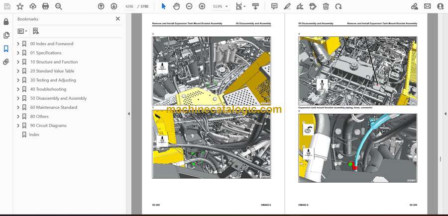