Format: PDF (Printable Document)
File Language: English
File Pages: 212
File Size: 41.85 MB (Speed Download Link)
Brand: Komatsu
Model: JRRP360-1, JRRP490-1 Attachment
Book No: RENBM0101-00
Type of Document: Shop Manual
$ 45
These Komatsu JRRP360-1, JRRP490-1 attachments are production tools—usually hanging off mid-size to larger carriers doing demolition, processing, or heavy material handling. The Komatsu JRRP360-1, JRRP490-1 Attachment Shop Manual (RENBM0101-00) is what shops reach for when something’s off and downtime is burning money. People buying this are usually trying to plan repairs, shorten diagnostics, and avoid parts-guessing and repeat tear-downs.
What this manual helps you do
Who this is for
If you’re a field tech, shop mechanic, or fleet manager planning parts and repair windows, this shop manual fits what you need. Operators or trainees looking for basic use and daily checks will be happier with an operation/maintenance manual instead.
FAQ
Q: Is this a PDF I can search and print?
A: Yes, this type of shop manual is normally supplied as a searchable PDF that you can print specific sections for the bench or field.
Q: Is the content deep enough for full overhauls?
A: The Shop Manual for Komatsu JRRP360-1, JRRP490-1 Attachment walks through diagnostic procedures, disassembly sequences, and reference data used during workshop-level repairs.
Q: How do I know it matches my exact attachment variant?
A: You’ll want to match your attachment’s ID plate and model to JRRP360-1 or JRRP490-1 and confirm the RENBM0101-00 reference with your Komatsu dealer if you’re on a borderline or special build.
Bottom line: If you’re scheduling and performing real repairs on JRRP360-1 or JRRP490-1 attachments, this is the right manual; if you just need operating tips or basic daily service, keep looking for an operator or O&M book.
TABLE OF CONTENTS
1. Index and foreword ……………………………………………………………………………… 5
1.1. Foreword, safety and general information ……………………………………………. 5
1.1.1. Safety notes and safety signs ……………………………………………………… 5
1.1.2. Personnel …………………………………………………………………………………. 8
1.1.3. Safety, warning and information labels …………………………………………. 8
1.1.4. Personal protective equipment …………………………………………………….. 9
1.1.5. Use for intended purpose ………………………………………………………….. 10
1.1.6. Use for not intended purpose …………………………………………………….. 10
1.2. Precautions …………………………………………………………………………………… 11
1.2.1. Personnel precautions ……………………………………………………………… 11
1.2.2. Explosion, fire and electric shock precautions ………………………………. 12
1.2.3. Support precautions …………………………………………………………………. 13
1.2.4. Hydraulic equipment precautions ……………………………………………….. 14
1.2.5. Maintenance/repair/assembly/disassembly precautions ………………… 15
1.2.6. Modifications or adjustment precautions ……………………………………… 17
2. Structures and operation …………………………………………………………………….. 19
2.1. Structures of the rotating pulveriser/demolition crusher ……………………….. 19
2.2. Principle function ……………………………………………………………………………. 21
3. Testing and adjustment ………………………………………………………………………. 25
3.1. Circuit diagram ………………………………………………………………………………. 25
3.1.1. Hydraulic motors diagram (rotate function) ………………………………….. 25
3.1.2. Hydraulic cylinder diagram (cutting/crushing function) …………………… 26
3.2. Hydraulic system and connections ……………………………………………………. 26
3.2.1. Connection of hydraulic hoses …………………………………………………… 27
3.2.2. Temperature of hydraulic system ……………………………………………….. 33
3.3. Mounting onto the excavator/carrier vehicle ……………………………………….. 33
3.4. Test run ………………………………………………………………………………………… 35
4. Troubleshooting ………………………………………………………………………………… 36
4.1. Foreword ………………………………………………………………………………………. 36
4.2. Troubleshooting ……………………………………………………………………………… 36
5. Maintenance and repair ……………………………………………………………………… 39
5.1. Maintenance scope and intervals ……………………………………………………… 39
5.2. Lubrication points and intervals ………………………………………………………… 40
5.3. Teeth, blades and jaws maintenance ………………………………………………… 49
5.3.1. Teeth ……………………………………………………………………………………… 49
5.3.2. Blades ……………………………………………………………………………………. 55
5.3.3. Welding of guards/ringlocks ………………………………………………………. 57
5.3.4. Hardfacing ………………………………………………………………………………. 60
5.4. Replacement of seals ……………………………………………………………………… 62
5.4.1. Cylinder seals ………………………………………………………………………….. 63
5.4.2. Swivel seals ……………………………………………………………………………. 72
5.4.3. Bearing slewing ring seals …………………………………………………………. 74
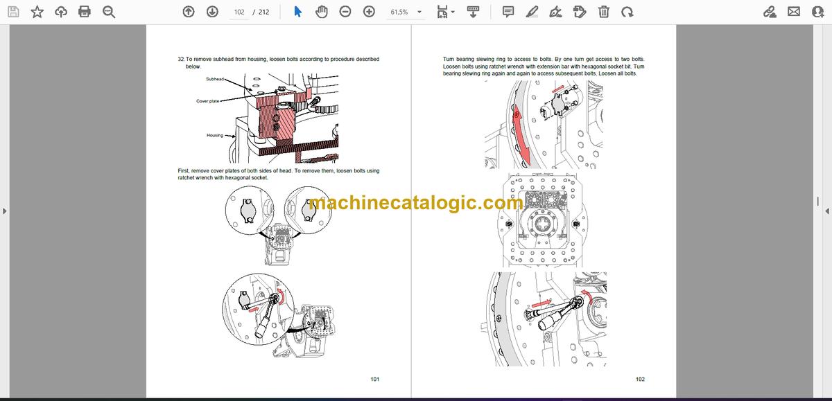
6. Disassembly/ Assembly ……………………………………………………………………… 76
6.1. Disassembly of the rotating pulveriser/demolition crusher ……………………. 76
6.2. Assembly of the rotating pulveriser/demolition crusher ………………………. 124
7. Appendix 1 – Technical Specification …………………………………………………. 187
7.1. Type JRRP – rotating pulveriser……………………………………………………… 187
7.1.1. General information ………………………………………………………………… 187
7.1.2. Hydraulic system ……………………………………………………………………. 188
7.1.3. Dimensions …………………………………………………………………………… 188
7.2. Type JRDC – demolition crusher …………………………………………………….. 188
7.2.1. General information ………………………………………………………………… 189
7.2.2. Hydraulic system ……………………………………………………………………. 189
7.2.3. Dimensions …………………………………………………………………………… 189
7.3. Hole patterns ……………………………………………………………………………….. 190
7.3.1. Hole pattern 140-150 ……………………………………………………………… 190
7.3.2. Hole pattern 150-160 ……………………………………………………………… 191
8. Appendix 2 – Fastener Manual ………………………………………………………….. 192
8.1. Thread treatment ………………………………………………………………………….. 192
8.1.1. Bolted connections with threaded blind holes …………………………….. 193
8.1.2. Bolted connections with nuts or threaded holes ………………………….. 195
8.1.3. Threaded hydraulic fittings connection ………………………………………. 198
8.2. Torque values………………………………………………………………………………. 201
8.2.1. Hexagon bolts and socket head cap bolts ………………………………….. 201
8.2.2. Hydraulic adapters …………………………………………………………………. 201
4
8.2.3. Hosefittings (DKOL, DKOS) for hydraulic applications …………………. 202
9. Appendix 3 – Assembly/Disassembly tools ………………………………………….. 203


