Format: PDF (Printable Document)
File Language: English
File Pages: 311
File Size: 43.45 MB (Speed Download Link)
Brand: Komatsu
Model: PC1250-11 PC1250-11E0 PC1250LC-11 PC1250LC-11E0 PC1250SP-11 PC1250SP-11E0 Hydraulic Excavator
Book No: GEN00203-09
Serial No: 50001 and up
Type of Document: Field Assembly Manual
$ 39
FOREWORD
CONTENTS
SPECIFICATIONS
PRECAUTIONS FOR FIELD ASSEMBLY
ASSEMBLING PROCEDURES, APPLICABLE EQUIPMENT AND SCHEDULE
KIT LAYOUT DIAGRAM
FLOW OF FIELD ASSEMBLY WORK
TRANSPORTATION
LIST OF FIELD ASSEMBLY TOOLS
TIGHTENING TORQUE
COATING MATERIALS
SELECTION OF WIRE ROPES USED FOR ASSEMBLY
A. ASSEMBLY OF CHASSIS
A-1 Install R.H. and L.H. track frames
A-2 Install travel piping
A-3 Install travel piping covers
A-4 Install steps
A-5 Install auto-greasing unit assembly(if equipped)
A-6 Add grease to swing circle
A-7 Assemble upper structure and undercarriage
A-8 Install R.H. side step
A-9 Install handrails
A-10 Install emergency stop switch on right front step (if equipped)
A-11 Install air cleaner cap
A-12 Install swivel travel piping
A-13 Install crawler undercover
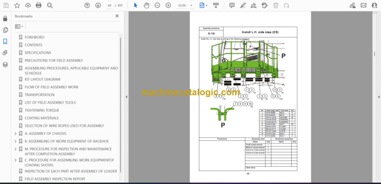
A-14 Install L.H. side step
A-15 Install L.H. side step (Machine with high cab (if equipped))
A-16 Install fixed ladder
A-17 Install hydraulic stairway (if equipped)
A-18 Install flash light (if equipped)
A-19 Install L.H. side step emergency stop switch (if equipped)
A-20 Install KomVision camera
A-21 Install counterweight
A-22 Install counterweight revolving warning lamp (if quipped)
A-23 Install counterweight rear lamp (if equipped)
A-24 Install radiator cover
A-25 Install exhaust tail pipe
A-26 Subassembly on top guard
A-27 Installation of top guard
A-28 Installation of cab
A-29 Assembly of parts inside cab
A-30 Change installed position of step light
A-31 Change installed position of wireless LAN antenna
A-32 Install operator’s cab revolving warning lamp (if equipped)
A-33 Install operator’s cab handrail
A-34 Install L.H. rearview mirror
A-35 Install R.H. rearview mirror
A-36 Prepare for bleeding air from travel motor
A-37 Bleed air from hydraulic pump section
A-38 Tighten swing circle mounting bolts to specified torque
A-39 Check and adjust track tension
A-40 Check fuel, coolant and oil levels
A-41 Parts to be touched up after field assembly
B. ASSEMBLING OF WORK EQUIPMENT OF BACKHOE
B-1 Release remaining pressure in hydraulic circuit
B-2 Install arm cylinder to boom
B-3 Install arm cylinder hose
B-4 Install boom cylinder to revolving frame
B-5 Install boom cylinder hose
B-6 Bleed air from cylinder
B-7 Install boom foot dust seal
B-8 Install boom assembly
B-9 Install boom cylinder to boom assembly
B-10 Install boom connection hoses (between chassis and boom assembly)
B-11 Install arm assembly
B-12 Install bucket cylinder hoses (between boom and bucket cylinder)
B-13 Install bucket assembly
B-14 Clearance standard for installation of work equipment
B-15 Install work equipment grease piping
B-16 Install work equipment lamps
B-17 Grease after assembling work equipment
B-18 Bleed air from swing motor
B-19 Bleed air from travel motor
B-20 Install travel motor guard
B-21 Bleed air from hydraulic stairway (if equipped)
M. PROCEDURE FOR INSPECTION AND MAINTENANCE AFTER COMPLETION ASSEMBLY
M-1 Replace return filter (Replace standard filter → flushing filter)
M-2 Flush hydraulic circuit
M-3 Replace return filter (Replace flushing filter with standard filter)
M-4 Replace pilot filter
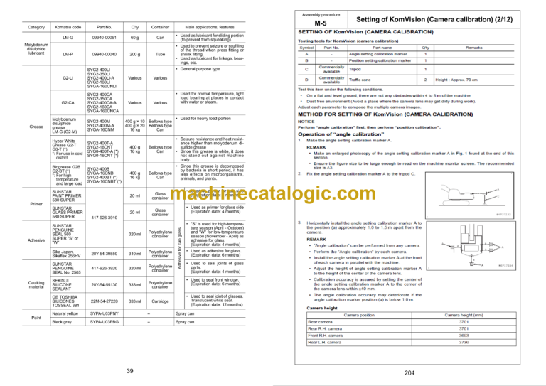
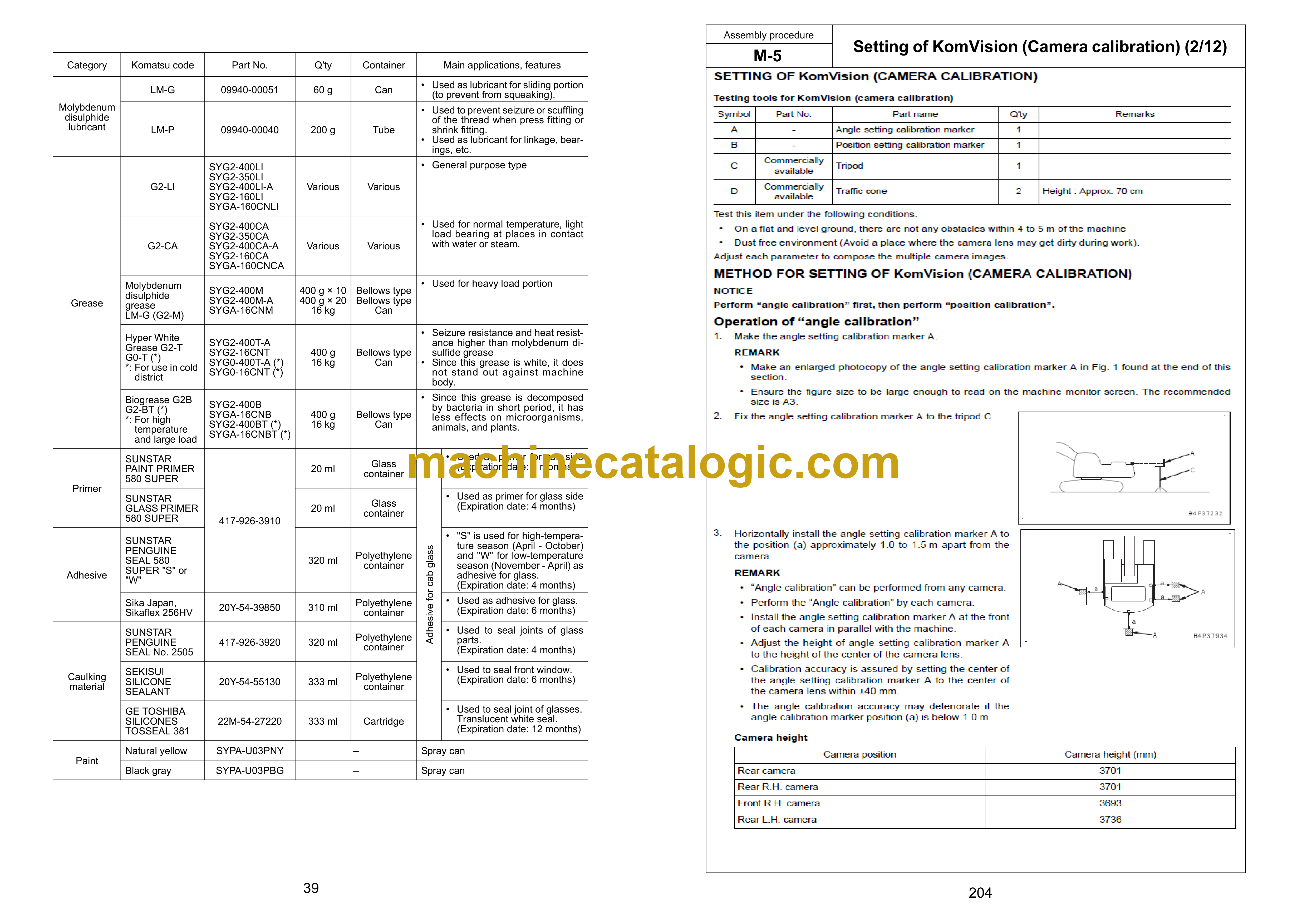
M-5 Setting of KomVision (Camera calibration)
M-6 Inspection method of 12 m visibility (KomVision)
M-7 Method for starting up KOMTRAX terminal and default setting of KOMTRAX Plus controller
C. PROCEDURE FOR ASSEMBLING WORK EQUIPMENTOF LOADING SHOVEL
TRANSPORTATION POSTURE (ONLY WORK EQUIPMENT OF LOADING SHOVEL)
C- 1. Release remaining pressure in hydraulic circuit
C- 2. Bleed air from cylinder
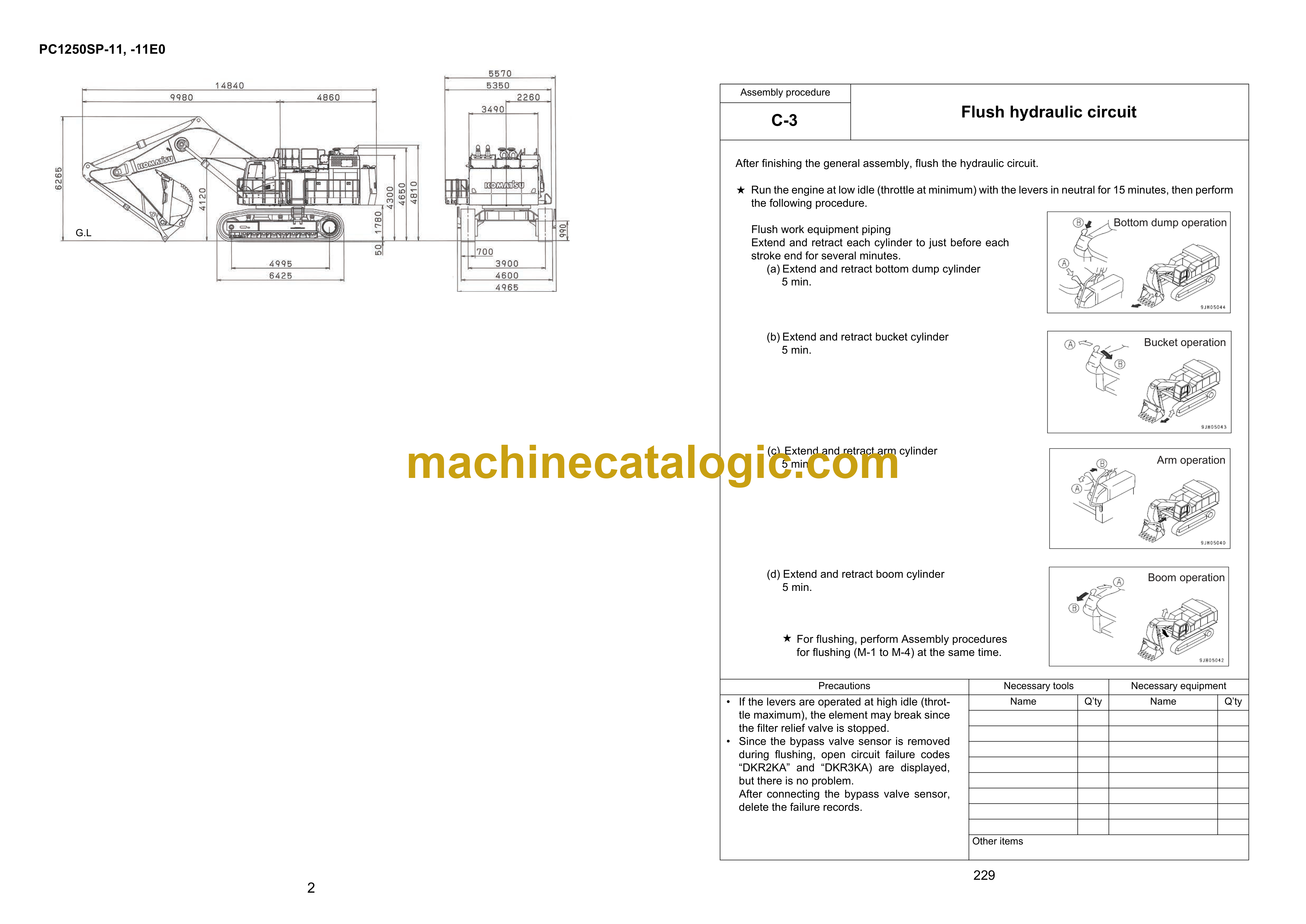
C- 3. Flush hydraulic circuit
C- 4. Installation of Arm Cylinder Bottoms
C- 5. Connection of Boom and Arm
C- 6. Pulling out Boom Foot Pin and Boom Cylinder Foot Pin
C- 7. Installation of Boom and Arm Assembly
C- 8. Installation of Boom Hoses (Between Chassis and Boom)
C- 9. Installation of Hoses Between Boom and Arm (Bottom Dump)
C-10. Installation of Boom Cylinder Bottoms
C-11. Installation of Boom Cylinder Hoses
C-12. Installation of Boom Cylinder Head Pin
C-13. Installation of Arm Cylinder Hoses
C-14. Installation of Bucket Cylinder
C-15. Installation of Bucket Cylinder Hoses
C-16. Installation of Bucket Assembly
C-17. Installation of Bottom Dump Cylinder Hoses
C-18. Maintenance Standard
C-19. Installation of Working Lamp
C-20. Installation of Work Equipment Greasing Piping
C-21. Checking Oil Level in Hydraulic Tank and Adding Oil
C-22. Greasing After Assembling Work Equipment
INSPECTION OF EACH PART AFTER ASSEMBLY OF LOADER
FIELD ASSEMBLY INSPECTION REPORT


