Komatsu PC170LC-11E0 Crawler Excavator Shop Manual (UENBM00683) (SN K77001-UP)
The Komatsu PC170LC-11E0 Crawler Excavator is a mid-size machine used for trenching, utility work, site prep, and general earthmoving. People who reach for the Komatsu PC170LC-11E0 Crawler Excavator Shop Manual (UENBM00683) are usually shop mechanics, field techs, or advanced operators who actually turn wrenches. They’re trying to diagnose faults, tear down components correctly, and put them back together without guesswork. I train new techs on this kind of material, and this is the level we use when we want them doing proper workshop repairs, not just daily checks.
What this manual helps you do
- Trace hydraulic issues by following hydraulic circuit layouts and step‑by‑step diagnostic routines.
- Check engine and fuel system problems using the guided troubleshooting trees most shops expect in a factory shop manual.
- Follow correct disassembly and reassembly sequences for major components like final drives, swing machinery, and cylinders.
- Diagnose electrical faults using wiring diagrams and typical test procedures for sensors, switches, and controllers.
- Verify adjustment procedures for items like track tension, control linkages, and machine settings after repairs.
Who this is for
This shop manual is aimed at field technicians, dealership or independent shop mechanics, and serious trainees working under supervision. If you only need basic operation, daily maintenance, or safety info, you’ll want the Operation and Maintenance Manual instead of this shop manual.
FAQ
Q: Is this a PDF I can search and print?
A: Yes, this is a digital PDF you can search by keyword and print pages for use in the shop.
Q: Is it deep enough for full overhauls?
A: Yes, the Komatsu PC170LC-11E0 Crawler Excavator Shop Manual walks through diagnostic procedures, disassembly sequences, and reference data used during workshop-level repairs.
Q: How do I know it matches my exact machine?
A: This manual is written for the PC170LC-11E0 variant; if your ID plate matches that model code, this is the correct shop manual to start from.
Bottom line: If you’re repairing or troubleshooting a PC170LC-11E0 in a workshop or field-service setting, this is the right manual; if you just run the machine, keep looking for the operator’s or maintenance book instead.
📘 Show Index
Komatsu PC170LC-11E0 Crawler Excavator Shop Manual (UENBM00683) (SN K77001-UP) Index:
- 00 Index and Foreword
- Index
- Abbreviation List
- Foreword, Safety, Basic Information
- How to Read the Shop Manual
- Safety Notice for Operation
- Precautions to Prevent Fire
- Procedures If Fire Occurs
- Precautions for Disposing of Waste Materials
- Engine Technology to Conform Exhaust Gas Emission
- Precautions for DEF
- General Character and Precautions for Handling
- Precautions for Adding
- Precautions for Storage
- Precautions for Fire Hazard and Leakage
- Other Precautions
- Store DEF
- Precautions When You Handle Hydraulic Equipment
- Precautions When You Disconnect and Connect Pipings
- Precautions When You Handle Electrical Equipment
- Precautions When You Handle Fuel System Equipment
- Precautions When You Handle Intake System Equipment
- Practical Use of KOMTRAX
- Disconnect and Connect Push-Pull Type Coupler
- How to Disconnect and Connect Type 1 Push-Pull Type Coupler
- How to Disconnect and Connect Type 2 Push-Pull Type Coupler
- How to Disconnect and Connect Type 3 Push-Pull Type Coupler
- Precautions for Disconnection and Connection of Connectors
- How to Disconnect and Connect Deutsch Connector
- How to Disconnect and Connect Slide Lock Type Connector
- How to Disconnect and Connect Connector with Lock to Pull
- How to Disconnect and Connect Connector with Lock to Push
- How to Disconnect and Connect Connector with Housing to Rotate
- How to Read the Codes for Electric Cable
- Explanation of Terms for Maintenance Standard
- Standard Tightening Torque Table
- Conversion Table
- 01 Specifications
- Table of Contents
- Abbreviation List
- Specifications
- Specification Drawing
- Specification Drawing: PC170LC-11E0
- Working Range Drawings
- Working Range: PC170LC-11E0
- Specifications
- Specifications: PC170LC-11E0
- Weight Table
- Weight Table: PC170LC-11E0
- Table of Fuel, Coolant, and Lubricants
- 10 Structure and Function
- Table of Contents
- Abbreviation List
- Urea SCR System
- Layout Drawing of Urea SCR System
- Urea SCR System Diagram (Divided Type)
- Function of Urea SCR System
- Function of AdBlue/DEF Supply System
- Inducement Strategy
- Component Parts of Urea SCR System
- SCR Assembly
- AdBlue/DEF Tank
- AdBlue/DEF Pump
- AdBlue/DEF Injector
- AdBlue/DEF Hose
- AdBlue/DEF Tank Heating Valve
- Boot-up System
- Layout Drawing of Boot-up System
- Engine System
- Layout Drawing of Engine System
- Specifications of Engine System
- Engine Control System
- System Diagram of Engine Control
- Function of Engine Control System
- Auto-Deceleration System
- System Diagram of Auto-Deceleration System
- Function of Auto-Deceleration System
- Operation of Auto-Deceleration System
- Engine Automatic Warm-up System
- System Diagram of Engine Automatic Warm-up System
- Function of Engine Automatic Warm-up System
- Overheat Prevention System
- Overheat Prevention System Diagram
- Function of Overheat Prevention System
- Turbocharger Protection System
- System Diagram of Turbocharger Protection System
- Function of Turbocharger Protection System
- Automatic Idle Stop System
- System Diagram of Automatic Idle Stop System
- Function of Automatic Idle Stop System
- Component Parts of Engine System
- Turbocharger
- KOMATSU Open Crankcase Ventilation System (Kocv)
- Impactor (Filterless)
- Exhaust Throttle Valve
- KDPF
- Cooling System
- Layout Drawing of Cooling System
- Specifications of Cooling System
- Fan Speed Control System of Fan Clutch
- Fan Speed Control System Diagram of Fan Clutch
- Function of Fan Speed Control System of Fan Clutch
- Engine Output Control System of Fan Clutch
- Engine Output Control System Diagram of Fan Clutch
- Function of Engine Output Control System of Fan Clutch
- Component Parts of Cooling System
- Control System
- Layout Drawing of Control System
- Machine Monitor System
- System Diagram of Machine Monitor System
- Function of Machine Monitor System
- KomVision System
- Layout Drawing of KomVision System
- System Diagram of KomVision System
- Function of KomVision System
- PPC Levers
- Automatic Grease System
- Sensor
- KOMTRAX System
- System Diagram of KOMTRAX System
- Function of KOMTRAX System
- Component Parts of Control System
- Machine Monitor
- Gateway Function Controller
- Communication Terminal
- KOMTRAX System
- KomVision Controller
- KomVision Camera
- Pump Controller
- Resistor for PC-EPC Valve
- CAN Terminating Resistor
- Engine Controller
- Fuel Control Dial
- Hydraulic System
- Layout Drawing of Hydraulic System
- CLSS
- Structure of CLSS
- Function of CLSS
- Engine and Pump Combined Control System
- Engine and Pump Combined Control System Diagram
- Function of Engine and Pump Combined Control System
- Pump and Valve Control System
- Pump and Valve Control System Diagram
- Function of Pump and Valve Control System
- Component Parts of Hydraulic System
- Hydraulic Tank
- Main Pump
- Pilot Oil Filter
- Control Valve
- Work Equipment System
- Layout Drawing of Work Equipment System
- One-Touch Power Maximizing System
- System Diagram of One-Touch Power Maximizing System
- Function of One-Touch Power Maximizing System
- PPC Lock System
- System Diagram of PPC Lock
- Function of PPC Lock System
- Work Equipment and Travel Automatic Lock System
- System Diagram of Lock Lever Automatic Lock System
- Function of Work Equipment and Travel Automatic Lock System
- Operation of Lock Lever Automatic Lock System
- Attachment Oil Flow Adjuster System
- Attachment Oil Flow Adjuster System Diagram
- Function of Attachment Oil Flow Adjuster System
- Tool Control System
- Tool Control System Diagram
- Function of Tool Control System
- Component Parts of Work Equipment System
- Work Equipment and Swing PPC Valve
- 1st-Line Attachment Oil Flow Adjuster EPC Valve
- 1st and 2nd Line Attachment Oil Flow Adjuster EPC Valve
- Blade PPC Valve
- Boom Swing PPC Valve
- 2-Piece Boom PPC Valve
- Solenoid Valve
- Boom Anti-drop Valve
- Arm Anti-Drop Valve
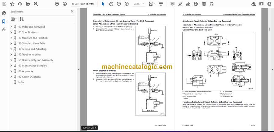
- Attachment Circuit Selector Valve (For High Pressure)
- Attachment Circuit Selector Valve (For Low Pressure)
- 1st-Line Attachment Variable Relief Valve
- 2nd-Line Attachment Variable Relief Valve
- Pilot Circuit Accumulator
- Attachment Circuit Accumulator
- Swing System
- Layout Drawing of Swing System
- Swing Control System Diagram
- Function of Swing Control System
- Component Parts of Swing System
- Swing Motor
- Swing Machinery
- Swing Circle
- Travel System
- Layout Drawing of Travel System
- System Diagram of Travel Control System
- Function of Travel Control System
- Component Parts of Travel System
- Travel Motor
- Final Drive
- Travel PPC Valve
- Center Swivel Joint
- Undercarriage and Frame
- Layout Drawing of Undercarriage
- Specifications of Undercarriage
- Work Equipment
- Structure of Work Equipment
- Function of Work Equipment
- Work Equipment Clearance Adjustment Shim
- Function of Work Equipment Clearance Adjustment Shim
- Bucket Clearance Adjustment Shim
- Function of Bucket Clearance Adjustment Shim
- CAB Related Parts
- ROPS CAB
- Structure of ROPS CAB
- Function of ROPS CAB
- CAB Mount
- Structure of CAB Mount
- Function of CAB Mount
- CAB Tipping Stopper
- Structure of CAB Tipping Stopper
- Function of CAB Tipping Stopper
- 20 Standard Value Table
- Table of Contents
- Abbreviation List
- Standard Value Table for Engine
- Standard Value Table for Engine: PC170LC-11E0
- Standard Value Table for Machine
- Standard Value Table for Machine: PC170LC-11E0
- Machine Posture and Procedures to Measure Performance
- Standard Value Table for Electricity
- Standard Value Table for Electricity
- 30 Testing and Adjusting
- Table of Contents
- Abbreviation List
- Related Information on Testing and Adjusting
- Tools for Testing and Adjusting
- Sketch of Tools for Testing and Adjusting
- Engine and Cooling System
- Examine Engine Speed
- How to Examine Engine High Idle Speed
- How to Examine Engine Low Idle Speed
- How to Examine Engine Speed at Pump Relief
- How to Examine Engine Speed (Engine Rated Speed) at Pump Relief + One-Touch Power Maximizing Function
- How to Examine Engine Speed at Auto-Deceleration
- Examine Boost Pressure
- How to Examine Boost Pressure on Machine Monitor
- How to Examine Boost Pressure by Testing Tool
- Examine Exhaust Gas Color
- How to Examine Exhaust Gas Color with the Handy Smoke Checker
- How to Examine Exhaust Gas Color with Smoke Meter
- Examine and Adjust Valve Clearance
- Examine Valve Clearance
- Adjust Valve Clearance
- Examine Compression Pressure
- How to Examine Compression Pressure
- Examine Blowby Pressure
- How to Examine Blowby Pressure
- Examine Engine Oil Pressure
- How to Examine Engine Oil Pressure
- Examine Fuel Pressure
- How to Examine Low-Pressure Circuit (Fuel Main Filter Inlet Side)
- How to Examine Low-Pressure Circuit (Pressure Difference)
- How to Examine Return Circuit
- How to Examine Negative Pressure Circuit
- Examine Fuel Discharge, Return and Leakage
- How to Examine Supply Pump Discharge Volume
- How to Examine Supply Pump Return Rate
- How to Examine Leakage from the Pressure Limiter
- How to Examine Return Rate of the Injector
- Bleed Air from Fuel System
- How to Bleed Air from Fuel System
- Examine Fuel Circuit for Leakage
- How to Examine Fuel Circuit for Leakage at Engine Stop
- How to Examine Fuel Circuit for Leakage at Engine Low Idle
- How to Examine Fuel Circuit for Leakage at Engine High Idle
- How to Examine Fuel Circuit for Leakage at Engine Rated Speed
- Handle Cylinder Cut-out Mode Operation
- Handle No-Injection Cranking Operation
- Examine KDPF, SCR and Muffler Stack for Looseness and Damage
- How to Examine KDPF, SCR and Muffler Stack for Looseness and Damage
- Examine Installed Condition of Cylinder Heads and Manifolds
- How to Examine Installed Condition of Cylinder Heads and Manifolds
- Examine Engine Piping for Damage and Looseness
- How to Examine Engine Piping for Damage and Looseness
- Examine and Adjust Air Conditioner Compressor Belt Tension
- How to Examine Air Conditioner Compressor Belt
- How to Adjust Air Conditioner Compressor Belt
- Write Correction for Ash in Soot Accumulation to Engine Controller
- How to Correct Soot Accumulation Correction Value by Ash Influence
- Examine Cooling Fan Speed
- How to Examine Cooling Fan Speed
- Examine SCR Related Functions
- Examine AdBlue/DEF Pump Raised Pressure
- Examine Injection Volume from AdBlue/DEF Injector
- Examine AdBlue/DEF Line Heater Relay 1
- Examine AdBlue/DEF Line Heater Relay 2
- Examine AdBlue/DEF Pump Heater Relay
- Examine AdBlue/DEF Tank Heater Valve
- Examine SCR Denitration Efficiency
- Clean AdBlue/DEF Tank
- How to Clean AdBlue/DEF Tank
- Clean AdBlue/DEF Pump
- How to Clean AdBlue/DEF Pump
- Bleed Air from Coolant Circuit of AdBlue/DEF Tank
- How to Bleed Air from Coolant Circuit of AdBlue/DEF Tank
- Power Train
- Examine Swing Circle Bearing Clearance
- How to Examine Swing Circle Bearing Clearance
- Undercarriage and Frame
- Examine and Adjust Track Tension
- How to Examine Track Tension
- How to Adjust Track Tension
- Hydraulic System
- Release Remained Pressure in Hydraulic Circuit
- How to Release Remained Pressure from Hydraulic Tank
- How to Release Remained Pressure in Hydraulic Cylinder Circuit
- How to Release Remained Pressure from Swing Motor Circuit
- How to Release Remained Pressure from Travel Motor Circuit
- Examine and Adjust Oil Pressure in Work Equipment, Swing, and Travel Circuits
- How to Examine Unload Pressure on Machine Monitor
- How to Examine Unload Pressure by Testing Tool
- How to Examine Work Equipment Relief Pressure on Machine Monitor
- How to Examine Work Equipment Relief Pressure by Testing Tool
- How to Examine Swing Relief Pressure on Machine Monitor
- How to Examine Swing Relief Pressure by Testing Tool
- How to Examine Travel Relief Pressure on Machine Monitor
- How to Examine Travel Relief Pressure by Testing Tool
- How to Adjust Work Equipment and Travel Relief Pressure
- How to Adjust Swing Relief Pressure
- Examine Oil Pressure of Control Circuit
- How to Examine Oil Pressure in Control Circuit
- Examine and Adjust Oil Pressure in Pump PC Control Circuit
- How to Examine PC Valve Outlet Pressure (Servo Piston Inlet Pressure)
- How to Examine PC-EPC Valve Outlet Pressure
- How to Adjust Oil Pressure in Pump PC Control Circuit
- Examine and Adjust Oil Pressure in Pump LS Control Circuit
- How to Examine LS Differential Pressure with Machine Monitor
- How to Examine LS Differential Pressure by Testing Tool
- How to Examine LS Valve Outlet Pressure (Servo Piston Inlet Pressure)
- How to Adjust LS Valve
- Examine Outlet Pressure of Solenoid Valve
- How to Examine Outlet Pressure of Solenoid Valve
- Operating Condition of Solenoid Valve
- Examine PPC Valve Outlet Pressure
- Examine Outlet Pressure in PPC Valve
- Adjust Play of Work Equipment and Swing PPC Valves
- How to Adjust Play of Work Equipment and Swing PPC Valves
- Examine Pump Swash Plate Sensor
- How to Examine pump swash plate sensor
- Examine and Adjust Travel Deviation
- How to Examine Travel Deviation
- How to Adjust Travel Deviation
- Examine Parts Which Cause Hydraulic Drift of Work Equipment
- How to Examine Parts Which Cause Hydraulic Drift of Boom Cylinder and Bucket Cylinder
- How to Examine the Parts Which Cause Hydraulic Drift of Arm Cylinder
- How to Examine Parts that Cause Hydraulic Drift of PPC Valve
- Examine Oil Leakage
- How to Examine Oil Leakage from Boom Cylinder
- How to Examine Oil Leakage from Arm Cylinder
- How to Examine Oil Leakage from Bucket Cylinder
- How to Examine Oil Leakage in 2-Piece Boom Cylinder
- How to Examine Oil Leakage from Swing Motor
- How to Examine Oil Leakage from Travel Motor
- Bleed Air from Hydraulic System
- How to Bleed Air from the Main Pump
- How to Bleed Air from Cylinder
- How to Bleed Air from Swing Motor
- How to Bleed Air from Travel Motor
- How to Examine Oil Level
- Examine and Charge Accumulator (Made by NOK) Nitrogen Gas Pressure for Attachment
- How to Examine Accumulator Nitrogen Gas Pressure for Attachment (Low Pressure Side)
- How to Examine Accumulator Nitrogen Gas Pressure for Attachment (High Pressure Side)
- Replace Accumulator Bladder on High Pressure Side for Attachment Piping
- How to Replace Accumulator Bladder on High Pressure Side for Attachment Piping
- Measure and Adjust Quick Coupler Control Valve Output Pressure
- CAB Related Parts
- Examine CAB Tipping Stopper
- How to Examine Cab Tipping Stopper
- Adjust Mirrors
- How to Adjust Machine Left Front Mirror (A)
- How to Adjust Regular Position of Machine Left Front Mirror (A)
- How to Adjust Machine Right Front Mirror (B)
- How to Adjust Regular Position of Machine Right Front Mirror (B)
- How to Adjust Machine Right Side Mirror (C)
- Electrical System
- Set and Operate Machine Monitor
- Operator Mode
- Service Mode
- How to Start Up KOMTRAX System
- Adjust rearview camera angle
- How to Adjust Rearview Camera Angle
- Adjust KomVision Camera Angle
- How to Adjust Front Right Camera, Rear Right Camera, and Rear Left Camera Angles
- How to Adjust Rear Camera Angle
- Set KomVision Related Function
- How to Set KomVision (Main Setting)
- How to Set KomVision (Camera Setting)
- How to Set KomVision (Camera Calibration)
- KomVision screen – Check 12 m visibility
- Handle Voltage Circuit of Engine Controller
- Handle Battery Disconnect Switch
- Examine Diodes
- How to Examine Diodes by Digital Tester
- How to Examine Diodes by Analog Tester
- Pm Clinic
- Pm Clinic Service
- Pm Clinic Check Sheet: PC170LC-11E0
- 40 Troubleshooting
- Table of Contents
- Abbreviation List
- Related Information to Troubleshooting
- General Troubleshooting Points
- Troubleshooting Points for Urea SCR System
- Sequence of Events in Troubleshooting
- Checks Before Troubleshooting
- Inspection Procedure Before Troubleshooting
- Test in Accordance with Testing Procedure
- How to Examine Fuel Level and Type
- How to Examine for Impure Ingredient in Fuel
- How to Examine Fuel Prefilter
- How to Examine Water Separator, Drain Water and Sediment
- How to Replace Fuel Prefilter Cartridge
- How to Examine Fuel Main Filter
- How to Examine Engine Oil Level (Oil Quantity in Oil Pan)
- How to Examine Coolant Level (Reservoir Tank)
- How to Examine Air Cleaner Clogging
- How to Clean Air Cleaner Outer Element
- How to Replace Air Cleaner Element
- How to Examine Hydraulic Oil Level
- How to Examine Hydraulic Oil Strainer
- How to Examine Hydraulic Oil Filter
- How to Examine Oil Level in Swing Machinery Case
- How to Examine Oil Level in Damper Case
- How to Examine Oil Level in Final Drive Case
- How to Bleed Air from Fuel System
- How to Bleed Air from Hydraulic System
- How to Examine Electric Equipment
- Automatic Grease System
- Find Malfunctions
- Malfunction Finding Procedures
- Preparation for Troubleshooting of Electrical System
- Preparation for Troubleshooting of Machine Monitor
- Preparation for Troubleshooting of Engine Controller
- Preparation for Troubleshooting of Pump Controller
- Preparation for Troubleshooting of Gateway Controller
- How to Disconnect and Connect Connector with a Special Lock
- Procedure for Troubleshooting
- Symptom and Troubleshooting Numbers
- Information Shown in Troubleshooting Table
- How to Diagnose Wiring Harness for Open Circuit of Pressure Sensor System
- Connector List and Layout
- Connector Contact Connection Table
- T-Branch Box and T-Branch Adapter Table
- Fuse Location Table
- Precautions When You Clean and Replace KDPF (KCSF and KDOC)
- Prepare Short Circuit Electrical Connector (For Failure Codes [CA1883] and [CA3135])
- Failure Code Table
- Troubleshooting by Failure Code (Display of Code)
- Failure Code [879AKA]
- Failure Code [879AKB]
- Failure Code [879BKA]
- Failure Code [879BKB]
- Failure Code [879CKA]
- Failure Code [879CKB]
- Failure Code [879DKZ]
- Failure Code [879EMC]
- Failure Code [879FMC]
- Failure Code [879GKX]
- Failure Code [989L00]
- Failure Code [989M00]
- Failure Code [989N00]
- Failure Code [A1U0N3]
- Failure Code [A1U0N4]
- Failure Code [A900FR]
- Failure Code [A900N6]
- Failure Code [A900NY]
- Failure Code [AA10NX]
- Failure Code [AB00KE]
- Failure Code [AQ10MB]
- Failure Code [AQ10N3]
- Failure Code [AS00R2]
- Failure Code [AS00R3]
- Failure Code [AS00R4]
- Failure Code [AS00R5]
- Failure Code [AS00R6]
- Failure Code [AS00ZK]
- Failure Code [AS10KM]
- Failure Code [AS10NR]
- Failure Code [AS10NT]
- Failure Code [B@BAZG]
- Failure Code [B@BAZK]
- Failure Code [B@BCNS]
- Failure Code [B@BCZK]
- Failure Code [B@HANS]
- Failure Code [CA115]
- Failure Code [CA122]
- Failure Code [CA123]
- Failure Code [CA131]
- Failure Code [CA132]
- Failure Code [CA144]
- Failure Code [CA145]
- Failure Code [CA153]
- Failure Code [CA154]
- Failure Code [CA187]
- Failure Code [CA227]
- Failure Code [CA234]
- Failure Code [CA238]
- Failure Code [CA239]
- Failure Code [CA249]
- Failure Code [CA256]
- Failure Code [CA271]
- Failure Code [CA272]
- Failure Code [CA322]
- Failure Code [CA324]
- Failure Code [CA331]
- Failure Code [CA332]
- Failure Code [CA343]
- Failure Code [CA351]
- Failure Code [CA352]
- Failure Code [CA386]
- Failure Code [CA428]
- Failure Code [CA429]
- Failure Code [CA435]
- Failure Code [CA441]
- Failure Code [CA442]
- Failure Code [CA451]
- Failure Code [CA452]
- Failure Code [CA488]
- Failure Code [CA515]
- Failure Code [CA516]
- Failure Code [CA553]
- Failure Code [CA555]
- Failure Code [CA556]
- Failure Code [CA559]
- Failure Code [CA689]
- Failure Code [CA691]
- Failure Code [CA692]
- Failure Code [CA697]
- Failure Code [CA698]
- Failure Code [CA731]
- Failure Code [CA741]
- Failure Code [CA742]
- Failure Code [CA743]
- Failure Code [CA778]
- Failure Code [CA1117]
- Failure Code [CA1664]
- Failure Code [CA1669]
- Failure Code [CA1673]
- Failure Code [CA1677]
- Failure Code [CA1678]
- Failure Code [CA1682]
- Failure Code [CA1683]
- Failure Code [CA1684]
- Failure Code [CA1686]
- Failure Code [CA1694]
- Failure Code [CA1695]
- Failure Code [CA1696]
- Failure Code [CA1712]
- Failure Code [CA1713]
- Failure Code [CA1714]
- Failure Code [CA1715]
- Failure Code [CA1776]
- Failure Code [CA1777]
- Failure Code [CA1843]
- Failure Code [CA1844]
- Failure Code [CA1879]
- Failure Code [CA1881]
- Failure Code [CA1883]
- Failure Code [CA1885]
- Failure Code [CA1887]
- Failure Code [CA1921]
- Failure Code [CA1922]
- Failure Code [CA1942]
- Failure Code [CA1993]
- Failure Code [CA2185]
- Failure Code [CA2186]
- Failure Code [CA2249]
- Failure Code [CA2311]
- Failure Code [CA2373]
- Failure Code [CA2374]
- Failure Code [CA2554]
- Failure Code [CA2637]
- Failure Code [CA2639]
- Failure Code [CA2771]
- Failure Code [CA2973]
- Failure Code [CA2976]
- Failure Code [CA3133]
- Failure Code [CA3134]
- Failure Code [CA3135]
- Failure Code [CA3142]
- Failure Code [CA3143]
- Failure Code [CA3144]
- Failure Code [CA3146]
- Failure Code [CA3147]
- Failure Code [CA3148]
- Failure Code [CA3151]
- Failure Code [CA3165]
- Failure Code [CA3228]
- Failure Code [CA3229]
- Failure Code [CA3231]
- Failure Code [CA3232]
- Failure Code [CA3235]
- Failure Code [CA3239]
- Failure Code [CA3241]
- Failure Code [CA3242]
- Failure Code [CA3251]
- Failure Code [CA3253]
- Failure Code [CA3254]
- Failure Code [CA3255]
- Failure Code [CA3256]
- Failure Code [CA3311]
- Failure Code [CA3312]
- Failure Code [CA3313]
- Failure Code [CA3314]
- Failure Code [CA3315]
- Failure Code [CA3316]
- Failure Code [CA3317]
- Failure Code [CA3318]
- Failure Code [CA3319]
- Failure Code [CA3321]
- Failure Code [CA3322]
- Failure Code [CA3497]
- Failure Code [CA3498]
- Failure Code [CA3545]
- Failure Code [CA3547]
- Failure Code [CA3558]
- Failure Code [CA3559]
- Failure Code [CA3562]
- Failure Code [CA3563]
- Failure Code [CA3567]
- Failure Code [CA3568]
- Failure Code [CA3571]
- Failure Code [CA3572]
- Failure Code [CA3574]
- Failure Code [CA3575]
- Failure Code [CA3577]
- Failure Code [CA3578]
- Failure Code [CA3583]
- Failure Code [CA3596]
- Failure Code [CA3649]
- Failure Code [CA3681]
- Failure Code [CA3682]
- Failure Code [CA3713]
- Failure Code [CA3717]
- Failure Code [CA3718]
- Failure Code [CA3725]
- Failure Code [CA3741]
- Failure Code [CA3748]
- Failure Code [CA3755]
- Failure Code [CA3866]
- Failure Code [CA3867]
- Failure Code [CA3868]
- Failure Code [CA4151]
- Failure Code [CA4152]
- Failure Code [CA4155]
- Failure Code [CA4156]
- Failure Code [CA4157]
- Failure Code [CA4158]
- Failure Code [CA4159]
- Failure Code [CA4161]
- Failure Code [CA4162]
- Failure Code [CA4163]
- Failure Code [CA4164]
- Failure Code [CA4165]
- Failure Code [CA4166]
- Failure Code [CA4168]
- Failure Code [CA4169]
- Failure Code [CA4171]
- Failure Code [CA4249]
- Failure Code [CA4251]
- Failure Code [CA4259]
- Failure Code [CA4261]
- Failure Code [CA4277]
- Failure Code [CA4459]
- Failure Code [CA4461]
- Failure Code [CA4731]
- Failure Code [CA4732]
- Failure Code [CA4739]
- Failure Code [CA4768]
- Failure Code [CA4769]
- Failure Code [CA4842]
- Failure Code [CA4952]
- Failure Code [CA5115]
- Failure Code [CA5179]
- Failure Code [CA5181]
- Failure Code [CA5271]
- Failure Code [CA5272]
- Failure Code [CA5273]
- Failure Code [CA5274]
- Failure Code [CA5275]
- Failure Code [CA5276]
- Failure Code [CA5383]
- Failure Code [CA5631]
- Failure Code [CA5632]
- Failure Code [CA5655]
- Failure Code [CA5689]
- Failure Code [CA5715]
- Failure Code [CA5716]
- Failure Code [CA5838]
- Failure Code [CA5864]
- Failure Code [CA5865]
- Failure Code [CA6513]
- Failure Code [D110KB]
- Failure Code [D19JKZ]
- Failure Code [D811MC]
- Failure Code [D862KA]
- Failure Code [D8ALKA]
- Failure Code [D8ALKB]
- Failure Code [D8AQKR]
- Failure Code [DA20MC]
- Failure Code [DA22KK]
- Failure Code [DA25KP]
- Failure Code [DA29KQ]
- Failure Code [DA2LKA]
- Failure Code [DA2LKB]
- Failure Code [DA2QKR]
- Failure Code [DA2RKR]
- Failure Code [DAF0KM]
- Failure Code [DAF0MB]
- Failure Code [DAF0MC]
- Failure Code [DAF8KB]
- Failure Code [DAF9KQ]
- Failure Code [DAFGMC]
- Failure Code [DAFLKA]
- Failure Code [DAFLKB]
- Failure Code [DAFQKR]
- Failure Code [DAZ9KQ]
- Failure Code [DAZQKR]
- Failure Code [DB2QKR]
- Failure Code [DB2RKR]
- Failure Code [DBP0KM]
- Failure Code [DBP0KT]
- Failure Code [DBP5KB]
- Failure Code [DBP5KY]
- Failure Code [DBPQKR]
- Failure Code [DDNRKA]
- Failure Code [DDNRKY]
- Failure Code [DDNS00]
- Failure Code [DFB1KZ]
- Failure Code [DFB2KZ]
- Failure Code [DFB3L8]
- Failure Code [DFB4L8]
- Failure Code [DFB5KZ]
- Failure Code [DFB6KZ]
- Failure Code [DGH2KA]
- Failure Code [DGH2KB]
- Failure Code [DHAAMA]
- Failure Code [DHACMA]
- Failure Code [DHA4KA]
- Failure Code [DHPAMA]
- Failure Code [DHPBMA]
- Failure Code [DHS3MA]
- Failure Code [DHS4MA]
- Failure Code [DHS5MA]
- Failure Code [DHS8MA]
- Failure Code [DHS9MA]
- Failure Code [DHSAMA]
- Failure Code [DHSBMA]
- Failure Code [DHSCMA]
- Failure Code [DHSDMA]
- Failure Code [DKR0MA]
- Failure Code [DKULKA]
- Failure Code [DKULKB]
- Failure Code [DKULKY]
- Failure Code [DLM5KA]
- Failure Code [DR10KA]
- Failure Code [DR12KA]
- Failure Code [DR20KA]
- Failure Code [DR21KX]
- Failure Code [DR30KA]
- Failure Code [DR31KX]
- Failure Code [DR40KA]
- Failure Code [DUMBKA]
- Failure Code [DUMBKB]
- Failure Code [DV00KA]
- Failure Code [DV00KB]
- Failure Code [DV20KB]
- Failure Code [DW43KA]
- Failure Code [DW43KB]
- Failure Code [DW43KY]
- Failure Code [DW45KA]
- Failure Code [DW45KB]
- Failure Code [DW45KY]
- Failure Code [DW4CKY]
- Failure Code [DW91KA]
- Failure Code [DW91KB]
- Failure Code [DW91KY]
- Failure Code [DWA2KA]
- Failure Code [DWA2KB]
- Failure Code [DWA2KY]
- Failure Code [DWJ0KA]
- Failure Code [DWJ0KB]
- Failure Code [DWJ0KY]
- Failure Code [DWK0KA]
- Failure Code [DWK0KB]
- Failure Code [DWK0KY]
- Failure Code [DWK2KA]
- Failure Code [DWK2KB]
- Failure Code [DWK2KY]
- Failure Code [DWN5KA]
- Failure Code [DWN5KB]
- Failure Code [DWN5KY]
- Failure Code [DWNSKA]
- Failure Code [DWNSKB]
- Failure Code [DWNSKY]
- Failure Code [DXA8KA]
- Failure Code [DXA8KB]
- Failure Code [DXE4KA]
- Failure Code [DXE4KB]
- Failure Code [DXE4KY]
- Failure Code [DXE7KA]
- Failure Code [DXE7KB]
- Failure Code [DXE7KY]
- Failure Code [DXE8KA]
- Failure Code [DXE8KB]
- Failure Code [DXE8KY]
- Failure Code [DXE9KA]
- Failure Code [DXE9KB]
- Failure Code [DXE9KY]
- Failure Code [DXEAKA]
- Failure Code [DXEAKB]
- Failure Code [DXEAKY]
- Failure Code [DXEKKA]
- Failure Code [DXEKKB]
- Failure Code [DXEKKY]
- Failure Code [DXELKA]
- Failure Code [DXELKB]
- Failure Code [DXELKY]
- Failure Code [DY20KA]
- Failure Code [DY20MA]
- Failure Code [DY2CKB]
- Failure Code [DY2DKB]
- Failure Code [DY2EKB]
- Troubleshooting of Electrical System (E-Mode)
- Engine Does Not Start (Engine Does Not Crank)
- Manual Preheating System Does Not Operate
- Automatic Preheating System Does Not Operate
- While Preheating is in Operation, Preheating Monitor Does Not Come On
- When Starting Switch is Turned to ON Position, Machine Monitor Shows Nothing
- While Starting Switch is Turned to ON Position (with Engine Stopped), Engine Oil Level Monitor Comes On in Yellow
- While Starting Switch is Turned to ON Position (with Engine Stopped), Radiator Coolant Level Monitor Comes On in Yellow
- Engine Coolant Temperature Monitor Comes On While Engine is in Operation
- Hydraulic Oil Temperature Monitor Comes On in White While Engine Runs
- Air Cleaner Clogging Monitor Comes On in Yellow While Engine Runs
- Charge Level Monitor Comes On in Red While Engine is in Operation
- Fuel Level Monitor Comes On in Red While Engine Runs
- Water Separator Monitor Comes On in Red While Engine Runs
- Engine Coolant Temperature Monitor Comes On in Red While Engine is in Operation
- Engine Oil Pressure Monitor Comes on in Red While Engine is in Operation
- Hydraulic Oil Temperature Monitor Comes On in Red While Engine is in Operation
- Fuel Gauge Display Does Not Move from Minimum or Maximum
- Display of Fuel Gauge is Different from Actual Fuel Level
- Coolant Temperature Gauge Display Does Not Move from Minimum or Maximum
- Display of Coolant Temperature Gauge is Different from Actual Coolant Temperature
- Hydraulic Oil Temperature Gauge Display Does Not Move from Minimum or Maximum
- Display of Hydraulic Oil Temperature Gauge is Different from Actual Oil Temperature
- Some Areas of Machine Monitor Screen are Not Shown
- Function Switch Does Not Operate
- Automatic Warm-up System Does Not Work (in Cold Weather)
- When Auto-Decelerator Switch is Operated, Auto-Decelerator Monitor Does Not Come On or Does Not Go Out
- Auto-Decelerator is Not Operated or Canceled with Lever
- When Working Mode Switch is Operated, Working Mode Selection Screen is Not Shown
- When Working Mode is Changed, Setting of Engine and Hydraulic Pump is Not Changed
- When Travel Speed Switch is Operated, Travel Speed Monitor Does Not Change
- When Travel Speed Selection is Changed, Actual Travel Speed Does Not Change
- Alarm Buzzer Cannot be Canceled
- Service Meter is Not Shown, While Starting Switch is in OFF Position
- Service Mode Cannot be Selected
- All of Work Equipment, Swing, and Travel Mechanism Do Not Move
- All Work Equipment, Swing and Travel Do Not Lock
- When Swing Brake Cancel Switch is Set to Cancel Position, Machine Cannot Swing
- When Swing Brake Cancel Switch is Set to Normal Position, Swing Holding Brake Does Not Operate
- One-Touch Power Maximizing Function Does Not Operate Correctly or Monitor Does Not Show
- One-Touch Power Maximizing Function is Not Cancelled
- Alarm Does Not Sound During Travel
- Alarm Does Not Stop When Machine Stops
- Horn Does Not Sound
- Horn Does Not Stop
- When Wiper Switch is Operated, Wiper Monitor Does Not Come On or Go Out
- When Wiper Switch is Operated, Windshield Wiper Does Not Operate
- Window Washer Does Not Operate When Window Washer Switch is Operated
- "Boom RAISE" is Not Shown Correctly with Monitoring Function
- "Boom LOWER" is Not Shown Correctly with Monitoring Function
- "Arm OUT" is Not Shown Correctly with Monitoring Function
- "Arm IN" is Not Shown Correctly with Monitoring Function
- "Bucket DUMP" is Not Shown Correctly with Monitoring Function
- "Bucket CURL" is Not Shown Correctly with Monitoring Function
- "Swing" is Not Shown Correctly with Monitoring Function
- "Travel" is Not Shown Correctly with Monitoring Function
- Service is Not Shown Correctly with Monitoring Function
- Attachment Hydraulic Circuit Cannot be Changed
- KOMTRAX System Does Not Operate Correctly
- Troubleshooting for Hydraulic and Mechanical Systems (H Mode)
- Information Shown in Troubleshooting Table (H-Mode)
- Failure Mode and Cause Table
- All Work Equipment, Swing and Travel Do Not Work
- All Work Equipment, Swing and Travel Lack Speed and Power
- Fine Control Performance or Response is Unsatisfactory
- Unusual Noise is Heard from Around Hydraulic Pump
- Engine Speed Drops Largely or Engine Stops
- Speed or Power of Boom is Low
- Arm Speed or Power is Low
- Bucket Speed or Power is Low
- Work Equipment Does Not Move in Single Operation
- Hydraulic Drift of Boom is Large
- Hydraulic Drift of Arm is Large
- Hydraulic Drift of Bucket is Large
- When Single Work Equipment is Released Hydraulically, Other Work Equipment Moves
- Time Lag of Work Equipment is Large
- One-Touch Power Maximizing Function Does Not Operate
- Attachment Circuit Cannot be Changed
- Oil Flow in Attachment Circuit Cannot be Changed
- In Mixed Operation of Work Equipment, Work Equipment with Heavier Load Moves Slower
- In Mixed Operation of Swing and Travel, Travel Speed Decreases Largely
- In Mixed Operation of Swing and Boom RAISE, Boom RAISE Speed is Low
- Machine Does Not Travel Straight
- Machine is Not Steered Correctly or Steering Power is Low
- Travel Speed is Low
- One of Tracks Does Not Run
- Travel Speed Does Not Change, or Travel Speed is Too Slow or Fast
- Upper Structure Does Not Swing to Right and Left
- Upper Structure Swings Only to Right or Left
- Swing Acceleration or Swing Speed is Low in Right and Left Directions
- Swing Acceleration or Swing Speed is Low in Only One Direction
- Upper Structure Overruns Too Much When It Stops Swing Operation (Right and Left)
- Upper Structure Overruns Too Much When It Stops Swing Operation (Only One Direction)
- Shock is Large When Upper Structure Stops Swing Operation
- There is Large Unusual Noise When It Stops Swing Operation
- Swing Drift on a Slope is Large (While Swing Parking Brake is Applied)
- Swing Drift on a Slope is Large (While Swing Parking Brake is Released)
- Fan Speed is Abnormal (Too High or Low, or Does Not Rotate)
- Unusual Noise is Heard from Around Fan
- H-38 Quick coupler cylinder will not extend
- H-39 Quick coupler cylinder will not retract (but buzzer does not sound)
- H-40 Buzzer Does Not Operate (but Quick Coupler Cylinder Does Retract)
- H-41 Quick coupler cylinder extends and retracts slowly
- Troubleshooting of Engine (S-Mode)
- Information Shown in Troubleshooting Table (S-Mode)
- Engine Does Not Crank When Starting Switch is Turned to Start Position
- Engine Cranks but No Exhaust Smoke Comes Out
- Fuel is Injected but Engine Does Not Start (Misfiring: Engine Cranks but Does Not Start)
- Engine Startability is Unsatisfactory
- Engine Does Not Pick Up Smoothly
- Engine Stops During Operation
- Engine Runs Rough or is Not Stable
- Engine Lacks Power
- KDPF Gets Clogged In a Short Time
- Engine Oil Consumption is Excessive
- Oil Becomes Dirty Quickly
- Fuel Consumption is Excessive
- Oil is in Coolant (or Coolant Spurts Back or Coolant
- Oil Pressure Drops
- Fuel Mixes Into Engine Oil
- Water Mixes Into Engine Oil (Milky)
- Coolant Temperature Increases Too High (Overheating)
- Unusual Noise is Heard
- Vibration is Excessive
- Air Cannot be Bleed from Fuel Circuit
- Active Regeneration is Done Frequently
- Active Regeneration Continues Long
- White Smoke is Exhausted During Active Regeneration
- AdBlue/DEF Consumption is Excessive
- There is Unusual Smell (Irritating Odor)
- Foreign Materials Enter AdBlue/DEF (AdBlue/DEF Increases)
- 50 Disassembly and Assembly
- Table of Contents
- Abbreviation List
- Related Information on Disassembly and Assembly
- How to Read This Manual
- Coating Materials List
- Special Tool List
- Sketches of Special Tools
- Engine and Cooling System
- Remove and Install Supply Pump Assembly
- How to Remove Supply Pump Assembly
- How to Install Supply Pump Assembly
- Remove and Install Injector Assembly
- How to Remove Injector Assembly
- How to Install Injector Assembly
- Remove and Install Cylinder Head Assembly
- How to Remove Cylinder Head Assembly
- How to Install Cylinder Head Assembly
- Remove and Install Starter Assembly
- How to Remove Starting Motor Assembly
- How to Install Starting Motor Assembly
- Remove and Install Alternator Belt
- How to Remove Alternator Belt
- How to Install Alternator Belt
- Remove and Install Radiator Assembly
- How to Remove Radiator Assembly
- How to Install Radiator Assembly
- Remove and Install Hydraulic Oil Cooler Assembly
- How to Remove Hydraulic Oil Cooler Assembly
- How to Install Hydraulic Oil Cooler Assembly
- Remove and Install Aftercooler Assembly
- How to Remove Aftercooler Assembly
- How to Install Aftercooler Assembly
- Remove and Install Fan Clutch Assembly
- How to Remove Fan Clutch Assembly
- How to Install Fan Clutch Assembly
- Remove and Install Fan
- How to Remove Fan
- How to Install Fan
- Remove and Install Engine and Main Pump Assembly
- How to Remove Engine and Main Pump Assembly
- How to Install Engine and Main Pump Assembly
- Remove and Install Engine Front Oil Seal
- How to Remove Engine Front Oil Seal
- How to Install Engine Front Oil Seal
- Remove and Install Engine Rear Oil Seal
- How to Remove Engine Rear Oil Seal
- How to Install Engine Rear Oil Seal
- Remove and Install Fuel Cooler Assembly
- How to Remove Fuel Cooler Assembly
- How to Install Fuel Cooler Assembly
- Remove and Install Engine Hood Assembly
- How to Remove Engine Hood Assembly
- How to Install Engine Hood Assembly
- Remove and Install KDPF and SCR Assembly
- How to Remove KDPF and SCR Assembly
- How to Install KDPF and SCR Assembly
- Remove and Install KDPF Assembly
- How to Remove KDPF Assembly
- How to Install KDPF Assembly
- Disassemble and Assemble KDPF Assembly
- How to Disassemble KDPF Assembly
- How to Assemble KDPF Assembly
- Remove and Install Fuel Tank Assembly
- How to Remove Fuel Tank Assembly
- How to Install Fuel Tank Assembly
- Remove and Install AdBlue/DEF Tank Assembly
- How to Remove AdBlue/DEF Tank Assembly
- How to Install AdBlue/DEF Tank Assembly
- Remove and Install AdBlue/DEF Tank Sensor Flange Assembly
- How to Remove AdBlue/DEF Tank Sensor Flange Assembly
- How to Install AdBlue/DEF Tank Sensor Flange Assembly
- Remove and Install AdBlue/DEF Tank Sensor
- How to Remove AdBlue/DEF Tank Sensor
- How to Install AdBlue/DEF Tank Sensor
- Remove and Install AdBlue/DEF Tank Strainer
- How to Remove AdBlue/DEF Tank Strainer
- How to Install AdBlue/DEF Tank Strainer
- Remove and Install AdBlue/DEF Tank Filler Port Filter
- How to Remove AdBlue/DEF Tank Filler Port Filter
- How to Install AdBlue/DEF Tank Filler Port Filter
- Remove and Install SCR Assembly
- How to Remove SCR Assembly
- How to Install SCR Assembly
- Remove and Install AdBlue/DEF Injector
- How to Remove AdBlue/DEF Injector
- How to Install AdBlue/DEF Injector
- Remove and Install AdBlue/DEF Pump
- How to Remove AdBlue/DEF Pump
- How to Install AdBlue/DEF Pump
- Remove and Install AdBlue/DEF Hose
- How to Remove AdBlue/DEF Hose
- How to Install AdBlue/DEF Hose
- Remove and Install Air Cleaner Assembly
- How to Remove Air Cleaner Assembly
- How to Install Air Cleaner Assembly
- Remove and Install Air Conditioner Compressor Assembly
- How to Remove Air Conditioner Compressor Assembly
- How to Install Air Conditioner Compressor Assembly
- Remove and Install Air Conditioner Condenser Assembly
- How to Remove Air Conditioner Condenser Assembly
- How to Install Air Conditioner Condenser Assembly
- Remove and Install Oil Catch Tank
- How to Remove Oil Catch Tank
- How to Install Oil Catch Tank
- Power Train
- Remove and Install Travel Motor and Final Drive Assembly
- How to Remove Travel Motor and Final Drive Assembly
- How to Install Travel Motor and Final Drive Assembly
- Disassemble and Assemble Final Drive Assembly
- How to Disassemble Final Drive Assembly
- How to Assemble Final Drive Assembly
- Remove and Install Swing Motor and Swing Machinery Assembly
- How to Remove Swing Motor and Swing Machinery Assembly
- How to Install Swing Motor and Swing Machinery Assembly
- Disassemble and Assemble Swing Machinery Assembly
- How to Disassemble Swing Machinery Assembly
- How to Assemble Swing Machinery Assembly
- Remove and Install Swing Circle Assembly
- How to Remove Swing Circle Assembly
- How to Install Swing Circle Assembly
- Undercarriage and Frame
- Remove and Install Track Shoe Assembly
- How to Remove Track Shoe Assembly
- How to Install Track Shoe Assembly
- Remove and Install Sprocket
- How to Remove Sprocket
- How to Install Sprocket
- Remove and Install Idler and Idler Cushion Assembly
- How to Remove Idler and Idler Cushion Assembly
- How to Install Idler and Idler Cushion Assembly
- Disassemble and Assemble Idler Assembly
- How to Disassemble Idler Assembly
- How to Assemble Idler Assembly
- Disassemble and Assemble Idler Cushion Assembly
- How to Disassemble Idler Cushion Assembly
- How to Assemble Idler Cushion Assembly
- Disassemble and Assemble Track Roller Assembly
- How to Disassemble Track Roller Assembly
- How to Assemble Track Roller Assembly
- Disassemble and Assemble Carrier Roller Assembly
- How to Disassemble Carrier Roller Assembly
- How to Assemble Carrier Roller Assembly
- Remove and Install Revolving Frame Assembly
- Remove Revolving Frame Assembly
- Install Revolving Frame Assembly
- Remove and Install Counterweight Assembly
- How to Remove Counterweight Assembly
- How to Install Counterweight Assembly
- Hydraulic System
- Remove and Install Center Swivel Joint Assembly
- How to Remove Center Swivel Joint Assembly
- How to Install Center Swivel Joint Assembly
- Disassemble and Assemble Center Swivel Joint Assembly
- How to Disassemble Center Swivel Joint Assembly
- How to Assemble Center Swivel Joint Assembly
- Remove and Install Hydraulic Tank Assembly
- How to Remove Hydraulic Tank Assembly
- How to Install Hydraulic Tank Assembly
- Remove and Install Main Pump Assembly
- Remove Main Pump Assembly
- Install Main Pump Assembly
- Remove and Install Control Valve Assembly
- How to Remove Control Valve Assembly
- How to Install Control Valve Assembly
- Disassemble and Assemble Control Valve Assembly
- How to Assemble Control Valve Assembly
- How to Replace Pressure Reducing Valve Cartridge Assembly
- Disassemble and Assemble Work Equipment PPC Valve Assembly
- How to Disassemble Work Equipment PPC Valve Assembly
- How to Assemble Work Equipment PPC Valve Assembly
- Work Equipment
- Remove and Install Blade Assembly
- How to Remove Blade Assembly
- How to Install Blade Assembly
- Remove and Install Work Equipment Assembly
- How to Remove Work Equipment Assembly
- How to Install Work Equipment Assembly
- Remove and Install Boom Anti-drop Valve Assembly
- How to Remove Boom Anti-drop Valve Assembly
- How to Install Boom Anti-drop Valve Assembly
- Remove and Install Arm Anti-Drop Valve Assembly
- How to Remove Arm Anti-Drop Valve Assembly
- How to Install Arm Anti-Drop Valve Assembly
- Disassemble and Assemble Anti-Drop Valve Assembly
- How to Disassemble Anti-Drop Valve Assembly
- How to Assemble Anti-Drop Valve Assembly
- Disassemble and Assemble Work Equipment Cylinder Assembly
- How to Disassemble Work Equipment Cylinder Assembly
- How to Assemble Work Equipment Cylinder Assembly
- CAB Related Parts
- Remove and Install Operator Cab Assembly
- How to Remove Operator Cab Assembly
- How to Install Operator Cab Assembly
- Remove and Install Operator Cab Glass (Adhered Glass)
- How to Remove Operator Cab Glass (Adhered Glass)
- How to Install Operator Cab Glass (Adhered Glass)
- Remove and Install Front Window Assembly
- How to Remove Front Window Assembly
- How to Install Front Window Assembly
- Remove and Install Floor Frame Assembly
- How to Remove Floor Frame Assembly
- How to Install Floor Frame Assembly
- Remove and Install Air Conditioner Unit Assembly
- How to Remove Air Conditioner Unit Assembly
- How to Install Air Conditioner Unit Assembly
- Remove and Install Operator Seat
- How to Remove Operator Seat
- How to Install Operator Seat
- Remove and Install Seat Belt
- How to Remove Seat Belt
- How to Install Seat Belt
- Remove and Install Front Wiper Assembly
- How to Remove Front Wiper Assembly
- How to Install Front Wiper Assembly
- Electrical System
- Remove and Install Engine Controller Assembly
- How to Remove Engine Controller Assembly
- How to Install Engine Controller Assembly
- Remove and Install Pump Controller Assembly
- How to Remove Pump Controller Assembly
- How to Install Pump Controller Assembly
- Remove and Install KomVision Controller Assembly
- How to Remove KomVision Controller Assembly
- How to Install KomVision Controller Assembly
- Remove and Install Machine Monitor Assembly
- How to Remove Machine Monitor Assembly
- How to Install Machine Monitor Assembly
- Remove and Install Pump Swash Plate Sensor
- How to Remove Pump Swash Plate Sensor
- How to Install Pump Swash Plate Sensor
- Remove and Install Mass Air Flow and Temperature Sensor
- How to Remove Mass Air Flow and Temperature Sensor
- How to Install Mass Air Flow and Temperature Sensor
- Remove and Install Crankcase Pressure Sensor
- How to Remove Crankcase Pressure Sensor
- How to Install Crankcase Pressure Sensor
- Remove and Install SCR Temperature Sensor
- How to Remove SCR Temperature Sensor
- How to Install SCR Temperature Sensor
- Remove and Install Gateway Controller Assembly
- How to Remove Gateway Controller Assembly
- How to Install Gateway Controller Assembly
- 60 Maintenance Standard
- Table of Contents
- Abbreviation List
- Engine and Cooling System
- Maintenance Standard for Engine Mount
- Maintenance Standard for Cooling System
- Power Train
- Maintenance Standard for Swing Circle
- Maintenance Standard for Swing Machinery
- Maintenance Standard for Final Drive
- Maintenance Standard for Sprocket
- Maintenance Standard for Sprocket Tooth Profile Full-Scale Drawing
- Undercarriage and Frame
- Maintenance Standard for Track Frame and Idler Cushion
- Maintenance Standard for Idler
- Maintenance Standard for Track Roller
- Maintenance Standard for Carrier Roller
- Maintenance Standard for Track Shoes
- Maintenance Standard for Triple Shoes
- Maintenance Standard for Road Liner
- Hydraulic System
- Maintenance Standard for Hydraulic Tank
- Maintenance Standard for Main Pump
- Maintenance Standard for PC-EPC Valve
- Maintenance Standard for Travel Motor
- Maintenance Standard for Control Valve
- Maintenance Standard for Boom Anti-Drop Valve
- Maintenance Standard for Arm Anti-Drop Valve
- Maintenance Standard for Work Equipment and Swing PPC Valve
- Maintenance Standard for Travel PPC Valve
- Maintenance Standard for Blade PPC Valve
- Maintenance Standard for Solenoid Valve
- Maintenance Standard for Attachment Circuit Selector Valve (For High Pressure)
- Maintenance Standard for Attachment Circuit Selector Valve (For Low Pressure)
- Maintenance Standard for Center Swivel Joint
- Work Equipment
- Maintenance Standard for Work Equipment Linkage
- Dimensions of Arm
- Dimensions of Bucket
- Maintenance Standard for Work Equipment Linkage (2-Piece Boom)
- Maintenance Standard for Boom Cylinder
- Maintenance Standard for Boom Cylinder (2-Piece Boom Specification)
- Maintenance Standard for Arm Cylinder
- Maintenance Standard for Arm Cylinder (2-Piece Boom Specification)
- Maintenance Standard for Bucket Cylinder
- Maintenance Standard for Blade Cylinder
- Maintenance Standard for 2-Piece Boom Cylinder
- 80 Appendix
- Table of Contents
- Abbreviation List
- Air Conditioner System
- Precautions for Refrigerant
- Air Conditioner Component
- Specifications of Air Conditioner
- Structure and Function of Refrigeration Cycle
- Outline of Refrigeration Cycle
- Component Parts of Air Conditioner System
- Air Conditioner Unit
- Configuration Diagram of Air Conditioner Unit
- Function of Air Conditioner Unit
- Component Parts of Air Conditioner Unit
- Function of Evaporator as Air Conditioner Unit Component
- Function of Heater Core as Air Conditioner Unit Component
- Function of Evaporator Temperature Sensor as Air Conditioner Unit Component
- Function of Servo Motor as Air Conditioner Unit Component
- Structure of Expansion Valve as Air Conditioner Unit Component
- Function of Expansion Valve as Air Conditioner Unit Component
- Operate Expansion Valve as Air Conditioner Unit Component
- Function of Dual Pressure Switch
- Air Conditioner Controller
- Structure of Air Conditioner Controller
- Compressor
- Structure of Compressor
- Specifications of Compressor
- Function of Compressor
- Condenser
- Structure of Condenser
- Specifications of Condenser
- Function of Condenser
- Air Conditioner Related Sensors
- Structure of Sunlight Sensor
- Function of Sunlight Sensor
- Structure of Outside Temperature Sensor
- Function of Outside Air Temperature Sensor
- Explanation of Procedure for Test of and Troubleshooting of Air Conditioner
- Circuit Diagram and Configuration of Connector Pins of Air Conditioner
- System Diagram of Air Conditioner
- Input and Output Signals of Air Conditioner Controller
- Function of Air Conditioner Controller
- Locations of Air Conditioner Parts and Layout of Connectors
- Examine Air Leakage (Duct)
- How to Examine Air Leakage (Duct)
- Examine Air Conditioner With Self-Diagnosis Function
- Open the Electrical System Abnormality Record Screen in Service Mode of Machine Monitor
- Examine Vent (Mode) Changeover
- How to Examine Vent (Mode) Changeover
- Examine Fresh/Recirc Air Changeover
- How to Examine Fresh/Recirc Air Changeover
- Examine Sunlight Sensor
- How to Examine Sunlight Sensor
- Examine Refrigerant (Dual) Pressure Switch
- How to Examine Refrigerant (Dual) Pressure Switch
- Examine Relay
- Air Conditioner Troubleshooting Chart 1
- Air Conditioner Troubleshooting Chart 2
- Information Shown in Troubleshooting Table
- Failure Code [879AKA]
- Failure Code [879AKB]
- Failure Code [879BKA]
- Failure Code [879BKB]
- Failure Code [879CKA]
- Failure Code [879CKB]
- Failure Code [879DKZ]
- Failure Code [879EMC]
- Failure Code [879FMC]
- Failure Code [879GKX]
- A-1 Troubleshooting for Power Supply System (Air Conditioner Does Not Operate)
- A-2 Troubleshooting for Compressor and Refrigerant System (Air is Not Cooled)
- A-3 Troubleshooting for Blower Motor System (No Air Comes Out or Air Flow is Abnormal)
- A-4 Troubleshooting for Fresh/Recirc Air Changeover
- Troubleshooting by Gauge Pressure
- Connect Service Tool
- How to Connect Service Tool
- Precautions for Disconnection and Connection of Air Conditioner Piping
- Handle Compressor Oil
- How to Replace Desiccant
- 90 Circuit Diagrams
- Table of Contents
- Abbreviation List
- Hydraulic Circuit Diagram
- Symbols Used in Hydraulic Circuit Diagram
- Hydraulic Circuit Diagram (1/5)
- Hydraulic Circuit Diagram (2/5)
- Hydraulic Circuit Diagram (3/5)
- Hydraulic Circuit Diagram (4/5)
- Hydraulic Circuit Diagram (5/5)
- Electrical Circuit Diagram
- Symbols Used in Electric Circuit Diagram
- Electrical Circuit Diagram (1/9)
- Electrical Circuit Diagram (2/9)
- Electrical Circuit Diagram (3/9)
- Electrical Circuit Diagram (4/9)
- Electrical Circuit Diagram (5/9)
- Electrical Circuit Diagram (6/9)
- Electrical Circuit Diagram (7/9)
- Electrical Circuit Diagram (8/9)
- Electrical Circuit Diagram (9/9)
- Index
Komatsu


