Komatsu PC220NLCi-12 Crawler Excavator Shop Manual (UENBM00892)
This Komatsu PC220NLCi-12 Crawler Excavator Shop Manual (UENBM00892) is meant for people actually tearing into the machine, not just doing daily checks. The PC220NLCi-12 is a mid-size crawler excavator used for bulk earthmoving, trenching, and GPS-guided finish work. Folks who usually reach for this kind of book are field techs, dealer shops, and serious owner-operators trying to get a dead machine earning again without waiting on a service truck. They’re usually chasing faults, planning big component swaps, or verifying work before sending the machine back out.
What this manual helps you do
- Trace hydraulic issues in the main and auxiliary circuits so you can decide if it’s a control problem, a pump issue, or something downstream.
- Diagnose engine and fuel-system faults on the diesel powerplant using step-by-step checks with the tools you’ve actually got in the truck.
- Follow disassembly and reassembly sequences for major components like swing gear, travel motors, cylinders, and structural parts.
- Check electrical and electronic control systems, including wiring routes and sensor/actuator locations, to track down shorts, opens, and bad connections.
- Verify adjustment procedures after repairs so the excavator’s digging, tracking, and machine-control functions behave the way they should.
Who this is for
This shop manual is aimed at field technicians, dealership or independent shop mechanics, and fleet maintenance managers planning real repairs. If you’re just an operator wanting controls, dashboard meanings, and daily service points, you’d be better off with the Operation & Maintenance manual instead.
FAQ
Q: Is this a PDF I can download and search?
A: Yes, it’s a PDF you can download, search by keyword, and print the pages you need for the jobsite.
Q: Is the Komatsu PC220NLCi-12 Crawler Excavator Shop Manual good for full overhauls or just basic service?
A: This kind of shop manual usually covers workshop-level diagnostics, teardown, and reassembly, not just routine maintenance schedules.
Q: How do I know if UENBM00892 matches my exact machine variant?
A: You’ll want to match your machine’s model designation and serial tag against the seller’s stated coverage; if your plate says PC220NLCi-12 and they list that range, you’re in the right place.
Bottom line: If you’re the person actually fixing a PC220NLCi-12 and need repair procedures and diagnostics, this is the right manual; if you only need operating instructions and basic checks, keep looking for the O&M book instead.
📘 Show Index
Komatsu PC220NLCi-12 Crawler Excavator Shop Manual (UENBM00892) Index:
- 00 Index and Foreword
- Index
- Abbreviation List
- Foreword, Safety, Basic Information
- How to Read the Shop Manual
- Safety Notice for Operation
- Precautions to Prevent Fire
- Procedures If Fire Occurs
- Precautions for Disposing of Waste Materials
- Engine Technology to Conform Exhaust Gas Emission
- Precautions for DEF
- General Character and Precautions for Handling
- Precautions for Adding
- Precautions for Storage
- Precautions for Fire Hazard and Leakage
- Other Precautions
- Store DEF
- Precautions When You Handle Hydraulic Equipment
- Precautions When You Disconnect and Connect Pipings
- Precautions When You Handle Electrical Equipment
- Precautions When You Handle Fuel System Equipment
- Precautions When You Handle Intake System Equipment
- Practical Use of KOMTRAX
- Disconnect and Connect Push-Pull Type Coupler
- How to Disconnect and Connect Type 1 Push-Pull Type Coupler
- How to Disconnect and Connect Type 2 Push-Pull Type Coupler
- How to Disconnect and Connect Type 3 Push-Pull Type Coupler
- Precautions for Disconnection and Connection of Connectors
- How to Disconnect and Connect Deutsch Connector
- How to Disconnect and Connect Slide Lock Type Connector
- How to Disconnect and Connect Connector with Lock to Pull
- How to Disconnect and Connect Connector with Lock to Push
- How to Disconnect and Connect Connector with Housing to Rotate
- Standard Tightening Torque Table
- Conversion Table
- 01 Specifications
- Table of Contents
- Specifications
- Specification Drawing
- Specification Drawing: PC220LC-12, PC220LCI-12
- Specification Drawing: PC220NLC-12, PC220NLCI-12
- Working Range Drawings
- Working Range Drawings: PC220LC-12, PC220LCI-12
- Working Range Drawings: PC220NLC-12, PC220NLCI-12
- Specifications
- Specifications: PC220LC-12, PC220LCI-12
- Specifications: PC220NLC-12, PC220NLCI-12
- Weight Table
- Weight Table: PC220LC-12, PC220LCI-12
- Weight Table: PC220NLC-12, PC220NLCI-12
- Fuel, Coolant, Lubricant
- How to Use Fuel, Coolant and Lubricants by Ambient Temperature
- 10 Structure and Function
- Table of Contents
- Urea SCR System
- Layout Drawing of Urea SCR System (PC220LC-12, PC220LCI-12)
- Layout Drawing of Urea SCR System (PC220NLC-12, PC220NLCI-12)
- Urea SCR System Diagram
- Function of Urea SCR System
- Function of DEF System
- Inducement Strategy
- Component Parts of Urea SCR System
- SCR
- DEF Tank
- DEF Pump
- DEF Injector
- DEF Hose
- DEF Tank Heating Valve
- Boot-up System
- Layout Drawing of Boot-up System
- System Operating Lamp System
- System Diagram of System Operating Lamp System
- Function of Operation Lamp System
- Operation of System Operating Lamp System
- Battery Disconnect Switch
- Function of Battery Disconnect Switch
- Operation of Battery Disconnect Switch
- Starter Signal Unit System
- Starter Signal Unit System Diagram
- Function of Starter Signal Unit System
- Component Parts of Boot-Up System
- Starter Signal Unit
- Electric Key
- Engine System
- Layout Drawing of Engine System
- Specifications of Engine System
- Function of Engine System
- Engine Control System
- System Diagram of Engine Control
- Operation of Engine Control System
- Auto-Deceleration System
- System Diagram of Auto-Deceleration System
- Function of Auto-Deceleration System
- Operation of Auto-Deceleration System
- Engine Automatic Warm-up System
- System Diagram of Engine Automatic Warm-up System
- Function of Engine Automatic Warm-up System
- Overheat Prevention System
- Overheat Prevention System Diagram
- Function of Overheat Prevention System
- Turbocharger Protection System
- System Diagram of Turbocharger Protection System
- Function of Turbocharger Protection System
- Automatic Idle Stop System
- System Diagram of Automatic Idle Stop System
- Function of Automatic Idle Stop System
- Operation of Automatic Idle Stop System
- Delayed Engine Shutdown
- System Diagram of Delayed Engine Shutdown
- Function of Delayed Engine Shutdown
- Auto Power Off
- System Diagram of Auto Power Off
- Function of Auto Power Off
- Component Parts of Engine System
- Damper
- Turbocharger
- Crankcase Ventilation System
- Impactor (Filterless)
- Exhaust Throttle Valve
- KDPF
- Cooling System
- Layout Drawing of Cooling System
- Specifications of Cooling System
- Fan Speed Control System of Fan Clutch
- Fan Speed Control System Diagram of Fan Clutch
- Function of Fan Speed Control System of Fan Clutch
- Engine Output Control System of Fan Clutch
- Engine Output Control System Diagram of Fan Clutch
- Function of Engine Output Control System of Fan Clutch
- Component Parts of Cooling System
- Control System
- Layout Drawing of Control System
- Machine Monitor System
- System Diagram of Machine Monitor System
- Function of Machine Monitor System
- KomVision System
- System Diagram of KomVision System
- Function of KomVision System
- Automatic Grease System
- KOMTRAX System
- System Diagram of KOMTRAX System
- Function of KOMTRAX System
- Seat Belt Reminder System
- System Diagram of Seat Belt Reminder System
- Operation of Seat Belt Reminder System
- Radio Sound System
- System Diagram of Radio Sound System
- Function of Radio Sound System
- Remote Courtesy Lights System
- Remote Courtesy Lights System Diagram
- Operation of Remote Courtesy Lights System
- Switch of Work Equipment Control Lever
- System Diagram of Switch of Work Equipment Control Lever
- Function of Switch of Work Equipment Control Lever
- Travel Heading Indicator
- System Diagram of Travel Heading Indicator
- Function of Travel Heading Indicator
- Rollover Warning System
- System Diagram of Rollover Warning System
- Function of Rollover Warning System
- Component Parts of Control System
- Machine Monitor
- Monitor Controller
- KomVision Controller
- KomVision Camera
- KomVision Radar
- Gateway Function Controller
- Communication Terminal
- Valve Controller 1
- Valve Controller 2
- CAN Terminating Resistor
- Engine Controller
- Keypad
- Hydraulic System
- Layout Drawing of Hydraulic System (PC220LC-12, PC220LCI-12)
- Layout Drawing of Hydraulic System (PC220NLC-12, PC220NLCI-12)
- Electric and Hydraulic System (EHS)
- Structure of Electric and Hydraulic System (EHS)
- Operation of Bleed Valve and Unload Valve
- Pump Swash Plate Angle (Oil Flow) Control
- Engine and Pump Combined Control System
- Engine and Pump Combined Control System Diagram
- Function of Engine and Pump Combined Control System
- Pump and Valve Control System
- Pump and Valve Control System Diagram
- Function of Pump and Valve Control System
- Component Parts of Hydraulic System
- Hydraulic Tank
- Main Pump
- Control Valve
- Work Equipment System
- Layout Drawing of Work Equipment System
- Structure of Valve Control
- One-Touch Power Maximizing System
- System Diagram of One-Touch Power Maximizing System
- Function of One-Touch Power Maximizing System
- PPC Lock System
- System Diagram of PPC Lock
- Function of PPC Lock System
- Work Equipment and Travel Automatic Lock System
- System Diagram of Lock Lever Automatic Lock System
- Function of Work Equipment and Travel Automatic Lock System
- Operation of Lock Lever Automatic Lock System
- Cushion System for Boom Raise End
- System Diagram of Cushion System for Boom Raise End
- Function of Cushion System for Boom Raise End
- Operation of Cushion System for Boom Raise End
- Cushion System for Arm IN End
- Cushion System for Arm IN End Diagram
- Function of Cushion System for Arm IN End
- Operation of Cushion System for Arm IN End
- Attachment Oil Flow Adjuster System
- Attachment Oil Flow Adjuster System Diagram
- Function of Attachment Oil Flow Adjuster System
- Tool Control System
- Tool Control System Diagram
- Component Parts of Work Equipment System
- Work Equipment and Swing Electric Lever
- 1st-Line and 2nd-Line Attachment Electric Pedal
- Solenoid Valve
- Boom Anti-drop Valve
- Arm Anti-Drop Valve
- Attachment Circuit Selector Valve (For High Pressure)
- Attachment Circuit Selector Valve (For Low Pressure)
- Attachment Variable Relief Valve
- Pilot Circuit Accumulator
- Attachment Circuit Accumulator
- ICT System
- Layout Drawing of ICT System (3D Machine Control)
- System Diagram of Bucket Edge Position Detection System (3D Machine Control)
- Bucket Edge Position Detection System
- System Diagram of Bucket Edge Position Detection System
- Function of Bucket Edge Position Detection System
- Operation of Bucket Edge Position Detection System
- The Intelligent Machine Control System
- Function of Intelligent Machine Control System
- Auto Grade Assist Control
- Bucket Angle Hold Control
- Auto Stop Control
- Tilt Automatic Control (Machines with Auto Tilt Bucket)
- 2D Boundary Control
- Cab Interference Prevention
- Swing to Angle
- Auto Swing Control (3D Machine Control)
- 3D Boundary Control (3D Machine Control)
- Component Parts of ICT System
- Navigation Controller (3D Machine Control)
- Work Equipment Controller
- ICT Monitor (3D Machine Control)
- GNSS External Radio Device (3D Machine Control)
- GNSS Receiver (3D Machine Control)
- GNSS Antenna (3D Machine Control)
- IMU Sensor
- Stroke and Reset Sensor for Bucket Cylinder
- Swing System
- Layout Drawing of Swing System
- Swing Control System Diagram
- Function of Swing Control System
- Component Parts of Swing System
- Swing Motor
- Swing Machinery
- Swing Circle
- Travel System
- Layout Drawing of Travel System
- System Diagram of Travel Control System
- Function of Travel Control System
- Component Parts of Travel System
- Travel Motor
- Final Drive
- Travel Electric Pedal
- Center Swivel Joint
- Undercarriage and Frame
- Layout Drawing of Undercarriage
- Specifications of Undercarriage
- Work Equipment
- Structure of Work Equipment
- Function of Work Equipment
- Work Equipment Clearance Adjustment Shim
- Function of Work Equipment Clearance Adjustment Shim
- Bucket Clearance Adjustment Shim
- Function of Bucket Clearance Adjustment Shim
- CAB Related Parts
- ROPS CAB
- Structure of ROPS CAB
- Function of ROPS CAB
- CAB Mount
- Structure of CAB Mount
- Function of CAB Mount
- CAB Tipping Stopper
- Structure of CAB Tipping Stopper
- Function of CAB Tipping Stopper
- 20 Standard Value Table
- Table of Contents
- Standard Value Table for Engine
- Standard Value Table for Engine: PC220LC-12, PC220NLC-12
- Standard Value Table for Engine: PC220LCI-12,PC220NLCI-12
- Standard Value Table for Machine
- Standard Value Table for Machine: PC220LC-12, PC220NLC-12
- Standard Value Table for Machine: PC220LCI-12, PC220NLCI-12
- Machine Posture and Procedures to Measure Performance
- 30 Testing and Adjusting
- Table of Contents
- Precautions Before Work
- Related Information on Testing and Adjusting
- Tools for Testing and Adjusting
- Engine and Cooling System
- Examine Engine Speed
- How to Examine Engine Speed
- Examine Boost Pressure
- How to Examine Boost Pressure on Machine Monitor
- How to Examine Boost Pressure by Testing Tool
- Examine Exhaust Gas Color
- How to Examine Exhaust Gas Color with Handy Smoke Checker
- How to Examine Exhaust Gas Color with Smoke Meter
- Examine and Adjust Valve Clearance
- How to Examine Valve Clearance
- How to Adjust Valve Clearance
- Examine Compression Pressure
- How to Examine Compression Pressure
- Examine Blowby Pressure
- How to Examine Blowby Pressure
- Examine Engine Oil Pressure
- How to Examine Engine Oil Pressure
- Examine Starting Motor
- How to Examine Starting Motor
- Examine Fuel Pressure
- How to Examine Fuel Pressure
- Examine Fuel Discharge, Return and Leakage
- How to Examine Fuel Discharge, Return, and Leakage
- Bleed Air from Fuel System
- How to Bleed Air from Fuel System
- Examine Fuel Circuit for Leakage
- How to Examine Fuel System for Leakage
- Handle Cylinder Cut-out Mode Operation
- Handle No-Injection Cranking Operation
- Examine KDPF and SCR for Looseness and Damage
- How to Examine KDPF and SCR for Looseness and Damage
- Examine and Adjust Air Conditioner Compressor Belt Tension
- How to Examine Air Conditioner Compressor Belt
- How to Adjust Air Conditioner Compressor Belt
- Examine Fan Belt and Alternator Belt
- How to Examine Fan Belt and Alternator Belt
- Examine Auto-Tensioner
- How to Examine Auto-Tensioner
- Examine Cooling Fan Speed
- How to Examine Cooling Fan Speed
- Correct Soot Accumulation Correction Value by Ash Influence
- How to Correct Soot Accumulation Correction Value by Ash Influence
- Examine SCR Related Functions
- Examine DEF Pump Raised Pressure
- Examine Injection Volume from DEF Injector
- Examine DEF Line Heater Relay 1
- Examine DEF Line Heater Relay 2
- Examine DEF Pump Heater Relay
- Examine DEF Tank Heater Valve
- Examine SCR Denitration Efficiency
- Clean DEF Tank
- Clean DEF Pump
- Bleed Air from Coolant Circuit of AdBlue/DEF Tank
- How to Bleed Air from Coolant Circuit of DEF Tank
- Power Train
- Examine Swing Circle Bearing Clearance
- How to Examine Swing Circle Bearing Clearance
- Undercarriage and Frame
- Examine and Adjust Track Tension
- How to Examine Track Tension
- How to Adjust Track Tension
- Hydraulic System
- Release Remained Pressure in Hydraulic Circuit
- How to Release Remained Pressure from Hydraulic Tank
- How to Release Remained Pressure in Hydraulic Cylinder Circuit
- How to Release Remained Pressure from Swing Motor Circuit
- How to Release Remained Pressure from Travel Motor Circuit
- How to Release Remained Pressure from Attachment Circuit
- Examine and Adjust Oil Pressure in Work Equipment, Swing, and Travel Circuits
- How to Examine Oil Pressure in Work Equipment, Swing, and Travel Circuits
- How to Adjust Oil Pressure in Work Equipment, Swing, and Travel Circuits
- Examine Control Circuit Oil Pressure
- How to Examine Control Circuit Oil Pressure
- Examine and Adjust Pump LS Control Circuit Oil Pressure
- How to Examine Pump Electronic Control Valve Outlet Pressure (Servo Piston Inlet Pressure)
- Examine Solenoid Valve Outlet Pressure
- How to Examine Solenoid Valve Outlet Pressure
- Operating Condition of Solenoid Valve
- Examine EPC Valve Outlet Pressure
- How to Examine EPC Valve Outlet Pressure
- Examine Attachment Circuit Oil Pressure
- How to Examine Attachment Circuit Oil Pressure
- Examine Pump Swash Plate Sensor
- How to Examine Pump Swash Plate Sensor
- Examine Parts Which Cause Hydraulic Drift of Work Equipment
- How to Examine Parts Which Cause Hydraulic Drift of Boom Cylinder and Bucket Cylinder
- How to Examine Parts Which Cause Hydraulic Drift of Arm Cylinder
- Examine Oil Leakage
- How to Examine Oil Leakage from Boom Cylinder
- How to Examine Oil Leakage from Arm Cylinder
- How to Examine Oil Leakage from Bucket Cylinder
- How to Examine Oil Leakage from Swing Motor
- How to Examine Oil Leakage from Travel Motor
- Bleed Air from Hydraulic System
- How to Bleed Air from Hydraulic System
- Examine and Charge Accumulator (Made by HYDAC) Nitrogen Gas Pressure for Attachment (Low Pressure Side)
- How to Examine Accumulator (Made by HYDAC) Nitrogen Gas Pressure for Attachment (Low Pressure Side)
- Examine and Charge Accumulator Nitrogen Gas Pressure for Attachment (High Pressure Side)
- How to Examine Accumulator Nitrogen Gas Pressure for Attachment (High Pressure Side)
- Replace Accumulator Bladder on High Pressure Side for Attachment Piping
- How to Replace Accumulator Bladder on High Pressure Side for Attachment Piping
- CAB Related Parts
- Examine CAB Tipping Stopper
- How to Examine Cab Tipping Stopper
- How to Adjust Mirrors
- Procedure to Adjust Left Front Mirror (A)
- Procedure to Adjust Regular Position of Machine Left Front Mirror (A)
- Procedure to Adjust Right Front Mirror (B)
- Procedure to Adjust Regular Position of Machine Right Front Mirror (B) (PC220LC-12, PC220LCi-12)
- Procedure to Adjust Regular Position of Machine Right Front Mirror (B) (PC220NLC-12, PC220NLCi-12)
- Procedure to Adjust Machine Right Side Mirror (C) (PC220LC-12), (PC220LCi-12)
- Procedure to Adjust Machine Right Side Mirror (C) (PC220NLC-12), (PC220NLCi-12)
- Procedure to Adjust Regular Position of Machine Right Front Mirror (C) (PC220LC-12), (PC220LCi-12)
- Procedure to Adjust Regular Position of Machine Right Front Mirror (C) (PC220NLC-12, (PC220NLCi-12)
- Electrical System
- Set and Adjust Each Equipment
- How to Adjust by S-PRIT
- Adjustment Method by S-PRIT
- Set and Operate Machine Monitor
- Examine Function by LCD (Liquid Crystal Display)
- Examine Function of Service Meter
- Usage Limitation and Maintenance Password Change Function
- Set and Operate by SDT
- Monitoring
- Abnormality Record
- Maintenance
- Default Setting
- Adjustment
- Diagnostic tests
- Others
- Engine Menu
- How to Start Up KOMTRAX System
- How to Stop Use of KOMTRAX System
- Adjust KomVision Related Function
- Adjust Angle and Protrusion Dimension of KomVision Camera
- KomVision Screen – 12m Visibility Check
- Handle Voltage Circuit of Engine Controller
- Handle Battery Disconnect Switch
- Examine Diodes
- How to Examine Diodes by Digital Tester
- How to Examine Diodes by Analog Tester
- Pm Clinic
- Pm Clinic Service
- Pm Clinic Check Sheet: PC220LC-12
- Pm Clinic Check Sheet: PC220LCI-12
- 40 Troubleshooting
- Table of Contents
- Precautions Before Work
- Related Information to Troubleshooting
- General Troubleshooting Points
- Troubleshooting Points for Urea SCR System
- Sequence of Events in Troubleshooting
- Inspection Before Troubleshooting
- Inspection Procedure Before Troubleshooting
- Test in Accordance with Testing Procedure
- Examine Fuel Level and Type
- Examine for Impure Ingredient in Fuel
- How to Examine Fuel Prefilter
- Examine Water Separator, Drain Water and Sediment
- How to Replace Fuel Prefilter Cartridge
- Examine Fuel Main Filter
- Examine Engine Oil Level (Oil Quantity in Oil Pan)
- Examine Coolant Level (Expansion Tank)
- Examine Air Cleaner Clogging
- Clean Outer Element
- Replace Element
- Examine Hydraulic Oil Level
- Examine Hydraulic Oil Strainer (PC220LC-12), (PC220LCI-12)
- Examine Hydraulic Oil Strainer (PC220NLC-12), (PC220NLCI-12)
- Examine Hydraulic Oil Filter (PC220LC-12), (PC220LCI-12)
- Examine Hydraulic Oil Filter (PC220NLC-12), (PC220NLCI-12)
- Examine Oil Level in Swing Machinery Case
- Examine Oil Level in Final Drive Case
- Bleed Air from Fuel System
- Bleed Air from Hydraulic System
- How to Examine Electrical Components
- Preparation for Troubleshooting of Electrical System
- Inspection Procedure of Electrical System
- How to Examine Fuse
- How to Examine Fusible Link
- How to Examine Diodes
- How to Examine Relay
- How to Examine Switch
- How to Examine Sensor
- How to Examine When Sensor Power Supply is Defective
- How to Examine Solenoid and Actuation Device
- How to Examine Actuator
- Examine Wiring Harness
- How to Examine CAN Communication
- How to Examine Resistance
- How to Examine Power Supply to Controller
- Procedure for Troubleshooting
- Symptom and Troubleshooting Numbers
- Information Shown in Troubleshooting Table
- How to Diagnose Open Circuit of Hydraulic Pressure Sensor System Wiring Harness
- Connector List (PC220LC-12)
- Connector Layout (PC220LC-12) (1)
- Connector Layout (PC220LC-12) (2)
- Connector Layout (PC220LC-12) (3)
- Connector Layout (PC220LC-12) (4)
- Connector Layout (PC220LC-12) (5)
- Connector Layout (PC220LC-12) (6)
- Connector Layout (PC220LC-12) (7)
- Connector Layout (PC220LC-12) (8)
- Connectors List (PC220LCI-12)
- Connector Layout (PC220LCI-12) (1)
- Connector Layout (PC220LCI-12) (2)
- Connector Layout (PC220LCI-12) (3)
- Connector Layout (PC220LCI-12) (4)
- Connector Layout (PC220LCI-12) (5)
- Connector Layout (PC220LCI-12) (6)
- Connector Layout (PC220LCI-12) (7)
- Connector Layout (PC220LCI-12) (8)
- Connector Contact Connection Table
- T-Branch Box and T-Branch Adapter Table
- Fuse Location Table
- Precautions When You Clean and Replace KDPF (KCSF and KDOC)
- Prepare Short Circuit Electrical Connector (For Failure Codes [CA1883] and [CA3135])
- Failure Code Table
- Troubleshooting by Failure Code (Display of Code)
- Failure Code [6AZ0ZG]
- Failure Code [8761KX]
- Failure Code [879AKA]
- Failure Code [879AKB]
- Failure Code [879BKA]
- Failure Code [879BKB]
- Failure Code [879CKA]
- Failure Code [879CKB]
- Failure Code [879DKZ]
- Failure Code [879EMC]
- Failure Code [879FMC]
- Failure Code [879GKX]
- Failure Code [989800]
- Failure Code [989EKX]
- Failure Code [989H00]
- Failure Code [989HKM]
- Failure Code [989L00]
- Failure Code [989M00]
- Failure Code [A1U0N3]
- Failure Code [A1U0N4]
- Failure Code [AA10NX]
- Failure Code [AB00KE]
- Failure Code [AQ10MB]
- Failure Code [AS00R2]
- Failure Code [AS00R3]
- Failure Code [AS00R4]
- Failure Code [AS00R5]
- Failure Code [AS00R6]
- Failure Code [AS00ZK]
- Failure Code [AS10KM]
- Failure Code [AS10NR]
- Failure Code [AS10NT]
- Failure Code [B@BAZG]
- Failure Code [B@BAZK]
- Failure Code [B@BCNS]
- Failure Code [B@BCQA]
- Failure Code [B@BCZK]
- Failure Code [B@HANS]
- Failure Code [CA115]
- Failure Code [CA122]
- Failure Code [CA123]
- Failure Code [CA131]
- Failure Code [CA132]
- Failure Code [CA144]
- Failure Code [CA145]
- Failure Code [CA153]
- Failure Code [CA154]
- Failure Code [CA187]
- Failure Code [CA227]
- Failure Code [CA234]
- Failure Code [CA238]
- Failure Code [CA239]
- Failure Code [CA249]
- Failure Code [CA256]
- Failure Code [CA271]
- Failure Code [CA272]
- Failure Code [CA322]
- Failure Code [CA324]
- Failure Code [CA331]
- Failure Code [CA332]
- Failure Code [CA343]
- Failure Code [CA351]
- Failure Code [CA352]
- Failure Code [CA386]
- Failure Code [CA428]
- Failure Code [CA429]
- Failure Code [CA435]
- Failure Code [CA441]
- Failure Code [CA442]
- Failure Code [CA451]
- Failure Code [CA452]
- Failure Code [CA488]
- Failure Code [CA515]
- Failure Code [CA516]
- Failure Code [CA553]
- Failure Code [CA555]
- Failure Code [CA556]
- Failure Code [CA559]
- Failure Code [CA689]
- Failure Code [CA691]
- Failure Code [CA692]
- Failure Code [CA697]
- Failure Code [CA698]
- Failure Code [CA731]
- Failure Code [CA741]
- Failure Code [CA742]
- Failure Code [CA743]
- Failure Code [CA778]
- Failure Code [CA1117]
- Failure Code [CA1664]
- Failure Code [CA1669]
- Failure Code [CA1673]
- Failure Code [CA1677]
- Failure Code [CA1678]
- Failure Code [CA1682]
- Failure Code [CA1683]
- Failure Code [CA1684]
- Failure Code [CA1686]
- Failure Code [CA1695]
- Failure Code [CA1696]
- Failure Code [CA1712]
- Failure Code [CA1713]
- Failure Code [CA1714]
- Failure Code [CA1715]
- Failure Code [CA1776]
- Failure Code [CA1777]
- Failure Code [CA1843]
- Failure Code [CA1844]
- Failure Code [CA1879]
- Failure Code [CA1881]
- Failure Code [CA1883]
- Failure Code [CA1885]
- Failure Code [CA1887]
- Failure Code [CA1921]
- Failure Code [CA1922]
- Failure Code [CA1942]
- Failure Code [CA1993]
- Failure Code [CA2185]
- Failure Code [CA2186]
- Failure Code [CA2288]
- Failure Code [CA2311]
- Failure Code [CA2373]
- Failure Code [CA2374]
- Failure Code [CA2554]
- Failure Code [CA2555]
- Failure Code [CA2556]
- Failure Code [CA2639]
- Failure Code [CA2771]
- Failure Code [CA2973]
- Failure Code [CA2976]
- Failure Code [CA3133]
- Failure Code [CA3134]
- Failure Code [CA3135]
- Failure Code [CA3144]
- Failure Code [CA3146]
- Failure Code [CA3147]
- Failure Code [CA3148]
- Failure Code [CA3151]
- Failure Code [CA3165]
- Failure Code [CA3229]
- Failure Code [CA3231]
- Failure Code [CA3232]
- Failure Code [CA3235]
- Failure Code [CA3239]
- Failure Code [CA3241]
- Failure Code [CA3242]
- Failure Code [CA3251]
- Failure Code [CA3253]
- Failure Code [CA3254]
- Failure Code [CA3255]
- Failure Code [CA3256]
- Failure Code [CA3311]
- Failure Code [CA3312]
- Failure Code [CA3313]
- Failure Code [CA3314]
- Failure Code [CA3315]
- Failure Code [CA3316]
- Failure Code [CA3317]
- Failure Code [CA3318]
- Failure Code [CA3319]
- Failure Code [CA3321]
- Failure Code [CA3322]
- Failure Code [CA3497]
- Failure Code [CA3498]
- Failure Code [CA3545]
- Failure Code [CA3547]
- Failure Code [CA3558]
- Failure Code [CA3559]
- Failure Code [CA3562]
- Failure Code [CA3563]
- Failure Code [CA3567]
- Failure Code [CA3568]
- Failure Code [CA3571]
- Failure Code [CA3572]
- Failure Code [CA3574]
- Failure Code [CA3575]
- Failure Code [CA3577]
- Failure Code [CA3578]
- Failure Code [CA3583]
- Failure Code [CA3596]
- Failure Code [CA3649]
- Failure Code [CA3681]
- Failure Code [CA3682]
- Failure Code [CA3713]
- Failure Code [CA3725]
- Failure Code [CA3741]
- Failure Code [CA3748]
- Failure Code [CA3755]
- Failure Code [CA3866]
- Failure Code [CA3868]
- Failure Code [CA4151]
- Failure Code [CA4155]
- Failure Code [CA4156]
- Failure Code [CA4157]
- Failure Code [CA4158]
- Failure Code [CA4161]
- Failure Code [CA4162]
- Failure Code [CA4163]
- Failure Code [CA4168]
- Failure Code [CA4169]
- Failure Code [CA4171]
- Failure Code [CA4249]
- Failure Code [CA4251]
- Failure Code [CA4259]
- Failure Code [CA4277]
- Failure Code [CA4459]
- Failure Code [CA4461]
- Failure Code [CA4731]
- Failure Code [CA4732]
- Failure Code [CA4739]
- Failure Code [CA4768]
- Failure Code [CA4769]
- Failure Code [CA4842]
- Failure Code [CA4952]
- Failure Code [CA5115]
- Failure Code [CA5179]
- Failure Code [CA5181]
- Failure Code [CA5271]
- Failure Code [CA5272]
- Failure Code [CA5273]
- Failure Code [CA5274]
- Failure Code [CA5275]
- Failure Code [CA5276]
- Failure Code [CA5383]
- Failure Code [CA5632]
- Failure Code [CA5655]
- Failure Code [CA5689]
- Failure Code [CA5715]
- Failure Code [CA5716]
- Failure Code [CA5838]
- Failure Code [CA5864]
- Failure Code [CA5865]
- Failure Code [CA5938]
- Failure Code [CA6771]
- Failure Code [D014KA]
- Failure Code [D01QKR]
- Failure Code [D106KA]
- Failure Code [D106KY]
- Failure Code [D107KA]
- Failure Code [D107KY]
- Failure Code [D10AKB]
- Failure Code [D10BKB]
- Failure Code [D10CKB]
- Failure Code [D162KA]
- Failure Code [D162KB]
- Failure Code [D183KA]
- Failure Code [D183KB]
- Failure Code [D183KY]
- Failure Code [D197KA]
- Failure Code [D197KY]
- Failure Code [D19JKA]
- Failure Code [D19JKB]
- Failure Code [D1M4KA]
- Failure Code [D1M4KY]
- Failure Code [D524KL]
- Failure Code [D524KU]
- Failure Code [D525KL]
- Failure Code [D525KN]
- Failure Code [D526KN]
- Failure Code [D527KN]
- Failure Code [D528KN]
- Failure Code [D528KP]
- Failure Code [D529KX]
- Failure Code [D52DKN]
- Failure Code [D52DKP]
- Failure Code [D52EKN]
- Failure Code [D52FKN]
- Failure Code [D52HKN]
- Failure Code [D52GKN]
- Failure Code [D52JKN]
- Failure Code [D52KKN]
- Failure Code [D52MKX]
- Failure Code [D52NKX]
- Failure Code [D52PKX]
- Failure Code [D52QKR]
- Failure Code [D52TKX]
- Failure Code [D52UKX]
- Failure Code [D52VKN]
- Failure Code [D52WKL]
- Failure Code [D52WKN]
- Failure Code [D52WKU]
- Failure Code [D52XKB]
- Failure Code [D52YKB]
- Failure Code [D52ZKR]
- Failure Code [D52ZKT]
- Failure Code [D52ZLA]
- Failure Code [D571KA]
- Failure Code [D571KB]
- Failure Code [D811MC]
- Failure Code [D862KA]
- Failure Code [D8ALKA]
- Failure Code [D8ALKB]
- Failure Code [D8G1KT]
- Failure Code [D8G1XZ]
- Failure Code [D8G6KT]
- Failure Code [D8GCKR]
- Failure Code [D8GDKA]
- Failure Code [D8GDKB]
- Failure Code [D8GEKB]
- Failure Code [D8GEKY]
- Failure Code [D8GPKR]
- Failure Code [D8N1MA]
- Failure Code [D8N2MA]
- Failure Code [DAF0MB]
- Failure Code [DAF0MC]
- Failure Code [DAF3KK]
- Failure Code [DAF9KQ]
- Failure Code [DAFEKB]
- Failure Code [DAFEKY]
- Failure Code [DAFGMC]
- Failure Code [DAFLKA]
- Failure Code [DAFLKB]
- Failure Code [DAFMKR]
- Failure Code [DAFPKR]
- Failure Code [DAFUKA]
- Failure Code [DAFUKB]
- Failure Code [DAFUKY]
- Failure Code [DASRKR]
- Failure Code [DAZ9KQ]
- Failure Code [DAZQKR]
- Failure Code [DB2QKR]
- Failure Code [DB2RKR]
- Failure Code [DB90KK]
- Failure Code [DB90KM]
- Failure Code [DB90MC]
- Failure Code [DB92KK]
- Failure Code [DB99KQ]
- Failure Code [DB9LKA]
- Failure Code [DB9LKY]
- Failure Code [DB9MKR]
- Failure Code [DB9PKR]
- Failure Code [DB9SKR]
- Failure Code [DBJ0KK]
- Failure Code [DBJ0KM]
- Failure Code [DBJ0KT]
- Failure Code [DBJ0MC]
- Failure Code [DBJ2KK]
- Failure Code [DBJ5KP]
- Failure Code [DBJ5KY]
- Failure Code [DBJ6KP]
- Failure Code [DBJ6KY]
- Failure Code [DBJ7KP]
- Failure Code [DBJ7KY]
- Failure Code [DBJ9KQ]
- Failure Code [DBJAKT]
- Failure Code [DBJBKP]
- Failure Code [DBJCKA]
- Failure Code [DBJCKY]
- Failure Code [DBJEKR]
- Failure Code [DBJEMA]
- Failure Code [DBJJKT]
- Failure Code [DBJJKY]
- Failure Code [DBJKKT]
- Failure Code [DBJKKY]
- Failure Code [DBJLKT]
- Failure Code [DBJLKY]
- Failure Code [DBJMKT]
- Failure Code [DBJMKY]
- Failure Code [DBJNKT]
- Failure Code [DBJNKY]
- Failure Code [DBJPKR]
- Failure Code [DBJSKR]
- Failure Code [DBJTKT]
- Failure Code [DBJTKY]
- Failure Code [DBJUKT]
- Failure Code [DBJUKY]
- Failure Code [DBK0KK]
- Failure Code [DBK0KM]
- Failure Code [DBK0KT]
- Failure Code [DBK0MC]
- Failure Code [DBK2KK]
- Failure Code [DBK5KP]
- Failure Code [DBK5KY]
- Failure Code [DBK6KP]
- Failure Code [DBK6KY]
- Failure Code [DBK7KP]
- Failure Code [DBK7KY]
- Failure Code [DBK8KB]
- Failure Code [DBK8KY]
- Failure Code [DBK9KQ]
- Failure Code [DBKAKT]
- Failure Code [DBKBKP]
- Failure Code [DBKCKA]
- Failure Code [DBKCKY]
- Failure Code [DBKEKR]
- Failure Code [DBKJKT]
- Failure Code [DBKJKY]
- Failure Code [DBKKKT]
- Failure Code [DBKKKY]
- Failure Code [DBKLKT]
- Failure Code [DBKLKY]
- Failure Code [DBKMKT]
- Failure Code [DBKMKY]
- Failure Code [DBKPKR]
- Failure Code [DBKSKR]
- Failure Code [DBKTKT]
- Failure Code [DBKTKY]
- Failure Code [DBP0KM]
- Failure Code [DBP0KT]
- Failure Code [DBPQKR]
- Failure Code [DBPWKR]
- Failure Code [DBPYKY]
- Failure Code [DBTLKB]
- Failure Code [DBTMKB]
- Failure Code [DBU0KA]
- Failure Code [DBU0KB]
- Failure Code [DBU0KK]
- Failure Code [DBU0KR]
- Failure Code [DBU0KT]
- Failure Code [DBULKA]
- Failure Code [DBULKB]
- Failure Code [DBUSKA]
- Failure Code [DBUSKR]
- Failure Code [DBUTKA]
- Failure Code [DBUTKN]
- Failure Code [DBUUKA]
- Failure Code [DBUUKN]
- Failure Code [DDNRKA]
- Failure Code [DDNRKB]
- Failure Code [DDNS00]
- Failure Code [DDUAKR]
- Failure Code [DDX2KR]
- Failure Code [DDX2MC]
- Failure Code [DDXEKR]
- Failure Code [DDXEMC]
- Failure Code [DDXPKA]
- Failure Code [DDXPKB]
- Failure Code [DDXRKA]
- Failure Code [DDXRKB]
- Failure Code [DE6SKR]
- Failure Code [DF0AKX]
- Failure Code [DF0BKX]
- Failure Code [DF0CKX]
- Failure Code [DF0DKX]
- Failure Code [DFG1KX]
- Failure Code [DFG1L8]
- Failure Code [DFG2KX]
- Failure Code [DFG2L8]
- Failure Code [DFG3KX]
- Failure Code [DFG3L8]
- Failure Code [DFG4KX]
- Failure Code [DFG4L8]
- Failure Code [DGH2KA]
- Failure Code [DGH2KB]
- Failure Code [DHA4KA]
- Failure Code [DHAAMA]
- Failure Code [DHACMA]
- Failure Code [DHF1KA]
- Failure Code [DHF1KB]
- Failure Code [DHF2KA]
- Failure Code [DHF2KB]
- Failure Code [DHF3KA]
- Failure Code [DHF3KB]
- Failure Code [DHF5KA]
- Failure Code [DHF5KB]
- Failure Code [DHM1KA]
- Failure Code [DHM1KB]
- Failure Code [DHM2KA]
- Failure Code [DHM2KB]
- Failure Code [DHM3KA]
- Failure Code [DHM3KB]
- Failure Code [DHPAKA]
- Failure Code [DHPAKB]
- Failure Code [DHPBKA]
- Failure Code [DHPBKB]
- Failure Code [DHPCKA]
- Failure Code [DHPCKB]
- Failure Code [DJF1KA]
- Failure Code [DJR1KA]
- Failure Code [DJR1KB]
- Failure Code [DK80KK]
- Failure Code [DK80KR]
- Failure Code [DK80KT]
- Failure Code [DK80MB]
- Failure Code [DK83KK]
- Failure Code [DK83KR]
- Failure Code [DK83KT]
- Failure Code [DK83MB]
- Failure Code [DK86KK]
- Failure Code [DK86KR]
- Failure Code [DK86KT]
- Failure Code [DK86MB]
- Failure Code [DK8CKR]
- Failure Code [DK8CKT]
- Failure Code [DK8CMB]
- Failure Code [DKD0KX]
- Failure Code [DKG1L8]
- Failure Code [DKR0KA]
- Failure Code [DKR0KB]
- Failure Code [DKR1KA]
- Failure Code [DKR1KB]
- Failure Code [DKR2KA]
- Failure Code [DKR2KB]
- Failure Code [DKR2NX]
- Failure Code [DKSTKA]
- Failure Code [DKSTKB]
- Failure Code [DKT8KA]
- Failure Code [DKT8KB]
- Failure Code [DKT9KA]
- Failure Code [DKT9KB]
- Failure Code [DKTAKA]
- Failure Code [DKTAKB]
- Failure Code [DKTLKA]
- Failure Code [DKTLKB]
- Failure Code [DKTMKA]
- Failure Code [DKTMKB]
- Failure Code [DKTNKA]
- Failure Code [DKTNKB]
- Failure Code [DKTPKA]
- Failure Code [DKTPKB]
- Failure Code [DKTQKA]
- Failure Code [DKTQKB]
- Failure Code [DKUJKA]
- Failure Code [DKUJKB]
- Failure Code [DKUJKY]
- Failure Code [DKUKKA]
- Failure Code [DKUKKB]
- Failure Code [DKUKKY]
- Failure Code [DKV0KA]
- Failure Code [DKV0KB]
- Failure Code [DKV1KA]
- Failure Code [DKV1KB]
- Failure Code [DKY4KA]
- Failure Code [DKY4KB]
- Failure Code [DKY5KA]
- Failure Code [DKY5KB]
- Failure Code [DKYAKA]
- Failure Code [DKYAKB]
- Failure Code [DKYCKA]
- Failure Code [DKYCKB]
- Failure Code [DKYEKA]
- Failure Code [DKYEKB]
- Failure Code [DKYFKA]
- Failure Code [DKYFKB]
- Failure Code [DKYKKA]
- Failure Code [DKYKKB]
- Failure Code [DLM5KA]
- Failure Code [DLM5MB]
- Failure Code [DQA1KB]
- Failure Code [DQA1KM]
- Failure Code [DQA1KR]
- Failure Code [DQA1KT]
- Failure Code [DQA1KY]
- Failure Code [DQA2KM]
- Failure Code [DQA2KR]
- Failure Code [DQA2KT]
- Failure Code [DQA3KB]
- Failure Code [DQA3KM]
- Failure Code [DQA3KR]
- Failure Code [DQA3KT]
- Failure Code [DQA3KY]
- Failure Code [DQA4KM]
- Failure Code [DQA4KR]
- Failure Code [DQA4KT]
- Failure Code [DR12KA]
- Failure Code [DR12KB]
- Failure Code [DR12KK]
- Failure Code [DR12KR]
- Failure Code [DR12KY]
- Failure Code [DR20KR]
- Failure Code [DR30KA]
- Failure Code [DR30KB]
- Failure Code [DR30KK]
- Failure Code [DR30KR]
- Failure Code [DR30KY]
- Failure Code [DR40KR]
- Failure Code [DU50KB]
- Failure Code [DUMBKA]
- Failure Code [DUMBKB]
- Failure Code [DV20KA]
- Failure Code [DV20KB]
- Failure Code [DV20KY]
- Failure Code [DW43KA]
- Failure Code [DW43KB]
- Failure Code [DW43KY]
- Failure Code [DW45KA]
- Failure Code [DW45KB]
- Failure Code [DW45KY]
- Failure Code [DW4NKB]
- Failure Code [DW4NKY]
- Failure Code [DW91KA]
- Failure Code [DW91KB]
- Failure Code [DW91KY]
- Failure Code [DWA2KA]
- Failure Code [DWA2KB]
- Failure Code [DWA2KY]
- Failure Code [DWK0KA]
- Failure Code [DWK0KB]
- Failure Code [DWK0KY]
- Failure Code [DWK2KA]
- Failure Code [DWK2KB]
- Failure Code [DWK2KY]
- Failure Code [DWK8KA]
- Failure Code [DWK8KB]
- Failure Code [DWK8KY]
- Failure Code [DWM1KA]
- Failure Code [DWM1KB]
- Failure Code [DWM1KY]
- Failure Code [DWN5KA]
- Failure Code [DWN5KB]
- Failure Code [DWN5KY]
- Failure Code [DXAAKA]
- Failure Code [DXAAKB]
- Failure Code [DXAAKY]
- Failure Code [DXABKA]
- Failure Code [DXABKB]
- Failure Code [DXABKY]
- Failure Code [DXE5KA]
- Failure Code [DXE5KB]
- Failure Code [DXE5KY]
- Failure Code [DXE6KA]
- Failure Code [DXE6KB]
- Failure Code [DXE6KY]
- Failure Code [DXE7KA]
- Failure Code [DXE7KB]
- Failure Code [DXE7KY]
- Failure Code [DXE8KA]
- Failure Code [DXE8KB]
- Failure Code [DXE8KY]
- Failure Code [DXE9KA]
- Failure Code [DXE9KB]
- Failure Code [DXE9KY]
- Failure Code [DXEAKA]
- Failure Code [DXEAKB]
- Failure Code [DXEAKY]
- Failure Code [DXEKKA]
- Failure Code [DXEKKB]
- Failure Code [DXEKKY]
- Failure Code [DXELKA]
- Failure Code [DXELKB]
- Failure Code [DXELKY]
- Failure Code [DXR0KA]
- Failure Code [DXR0KB]
- Failure Code [DXR0KY]
- Failure Code [DXR1KA]
- Failure Code [DXR1KB]
- Failure Code [DXR1KY]
- Failure Code [DXT1KA]
- Failure Code [DXT1KB]
- Failure Code [DXT1KY]
- Failure Code [DXT2KA]
- Failure Code [DXT2KB]
- Failure Code [DXT2KY]
- Failure Code [DXT3KA]
- Failure Code [DXT3KB]
- Failure Code [DXT3KY]
- Failure Code [DXT4KA]
- Failure Code [DXT4KB]
- Failure Code [DXT4KY]
- Failure Code [DXT5KT]
- Failure Code [DXT5KY]
- Failure Code [DXTAKA]
- Failure Code [DXTAKB]
- Failure Code [DXTAKY]
- Failure Code [DXTBKA]
- Failure Code [DXTBKB]
- Failure Code [DXTBKY]
- Failure Code [DXTCKA]
- Failure Code [DXTCKB]
- Failure Code [DXTCKY]
- Failure Code [DXTDKA]
- Failure Code [DXTDKB]
- Failure Code [DXTDKY]
- Failure Code [DXTEKA]
- Failure Code [DXTEKB]
- Failure Code [DXTEKY]
- Failure Code [DXTFKA]
- Failure Code [DXTFKB]
- Failure Code [DXTFKY]
- Failure Code [DXTGKA]
- Failure Code [DXTGKB]
- Failure Code [DXTGKY]
- Failure Code [DXTHKA]
- Failure Code [DXTHKB]
- Failure Code [DXTHKY]
- Failure Code [DXTJKA]
- Failure Code [DXTJKB]
- Failure Code [DXTJKY]
- Failure Code [DXTKKA]
- Failure Code [DXTKKB]
- Failure Code [DXTKKY]
- Failure Code [DXTLKA]
- Failure Code [DXTLKB]
- Failure Code [DXTLKY]
- Failure Code [DXTMKA]
- Failure Code [DXTMKB]
- Failure Code [DXTMKY]
- Failure Code [DXTNKA]
- Failure Code [DXTNKB]
- Failure Code [DXTNKY]
- Failure Code [DXTPKA]
- Failure Code [DXTPKB]
- Failure Code [DXTPKY]
- Failure Code [DXTQKA]
- Failure Code [DXTQKB]
- Failure Code [DXTQKY]
- Failure Code [DXTRKA]
- Failure Code [DXTRKB]
- Failure Code [DXTRKY]
- Failure Code [DXTSKA]
- Failure Code [DXTSKB]
- Failure Code [DXTSKY]
- Failure Code [DXTTKA]
- Failure Code [DXTTKB]
- Failure Code [DXTTKY]
- Failure Code [E111KT]
- Failure Code [E111MC]
- Failure Code [F312KA]
- Failure Code [F312KB]
- Failure Code [F313KA]
- Failure Code [F313KB]
- Failure Code [F314KA]
- Failure Code [F314KB]
- Failure Code [F315KB]
- Failure Code [F315KY]
- Failure Code [F316KB]
- Failure Code [F316KY]
- Failure Code [F317KA]
- Failure Code [F317KB]
- Failure Code [F318KB]
- Failure Code [F318KY]
- Failure Code [F319KB]
- Failure Code [F319KY]
- Failure Code [F31AKB]
- Failure Code [F31AKY]
- Failure Code [F31BKB]
- Failure Code [F31BKY]
- Failure Code [F31CKB]
- Failure Code [F31CKY]
- Failure Code [F31DKB]
- Failure Code [F31DKY]
- Failure Code [F31EKB]
- Failure Code [F31EKY]
- Failure Code [F7A0KQ]
- Failure Code [F7A0KT]
- Failure Code [F7A1KK]
- Failure Code [F7ALKB]
- Failure Code [F7AQKR]
- Failure Code [F7ARKR]
- Failure Code [F7ASKA]
- Failure Code [FE0AKA]
- Failure Code [FE0AKB]
- Failure Code [FE0AKM]
- Failure Code [FL0AKB]
- Failure Code [FL0ALD]
- Failure Code [FL0BKB]
- Failure Code [FL0BLD]
- Failure Code [FL0CLD]
- Failure Code [FL0DLD]
- Failure Code [FL0ELD]
- Failure Code [FL0FLD]
- Failure Code [FL0GLD]
- Failure Code [FL0HLD]
- Troubleshooting of Electrical System (E-Mode)
- Manual Preheating System Does Not Operate
- Automatic Preheating System Does Not Operate
- When Starting Switch is Turned to ON Position, Machine Monitor Shows Nothing
- While Starting Switch is Turned to ON Position, Engine Oil Level Caution Lamp Comes on in Yellow
- While Starting Switch is Turned to ON Position, Radiator Coolant Level Caution Lamp Comes on in Yellow
- While Starting Switch is Turned to ON Position, Engine Coolant Temperature Caution Lamp Comes on in White
- Hydraulic Oil Temperature Caution Lamp Comes on in White While Engine is in Operation
- Air Cleaner Clogging Caution Lamp Comes on in Yellow While Engine is in Operation
- Charge Level Caution Lamp Comes on in Red While Engine is in Operation
- Fuel Level Caution Lamp Comes on in Red While Engine is in Operation
- Water Separator Caution Lamp Comes on in Red While Engine is in Operation
- Engine Coolant Temperature Caution Lamp Comes on in Red While Engine is in Operation
- Engine Oil Pressure Caution Lamp Comes on in Red While Engine is in Operation
- Hydraulic Oil Temperature Caution Lamp Comes on in Red While Engine is in Operation
- Fuel Gauge Does Not Move from Minimum or Maximum
- Display of Fuel Gauge is Different from Actual Fuel Level
- Engine Coolant Temperature Gauge Display Does Not Move from Minimum or Maximum
- Display of Engine Coolant Temperature Gauge is Different from Actual Coolant Temperature
- Hydraulic Oil Temperature Gauge Does Not Move from Minimum or Maximum
- Display of Hydraulic Oil Temperature Gauge is Different from Actual Oil Temperature
- Some Areas of Machine Monitor Screen are Not Shown
- Machine Monitor Does Not Respond When You Tap it
- Automatic Warm-up System Does Not Operate (in Cold Weather)
- Auto-Deceleration Icon Does Not Change When You Tap it
- Auto-Decelerator is Not Operated or Canceled with Lever
- Working Mode Selector Screen is Not Shown When You Tap Working Mode Icon
- When Working Mode is Changed, Setting of Engine and Hydraulic Pump is Not Changed
- Travel Speed Icon Display Does Not Change When You Tap it
- Travel Speed Does Not Change Even When You Change Travel Speed
- Alarm Buzzer Does Not Stop When You Operate Mute Switch
- Service Meter is Not Shown While Starting Switch is in OFF Position
- All Work Equipment, Swing and Travel Do Not Operate
- All Work Equipment, Swing, Travel Cannot be Locked
- Machine Does Not Swing While Swing Parking Brake Release Switch is Set to Release Position
- While Swing Parking Brake Release Switch is Turned on, Swing Brake is Not Operated
- One-Touch Power Maximizing Function Does Not Operate Correctly or Monitor is Not Shown
- One-Touch Power Maximizing Function is Not Cancelled
- Travel Alarm Does Not Operate During Travel
- Travel Alarm Does Not Stop When Machine Stops
- Horn Does Not Sound
- Horn Does Not Stop
- Key Pad LED Does Not Come on or Go off When You Operate it
- Windshield Wiper Does Not Operate When Wiper Switch is Operated
- When Window Washer Switch is Operated, Window Washer Does Not Operate
- Brightness of Machine Monitor or Each Switch Does Not Change When You Operate Monitor Brightness Selector Switch
- Room Lamp Does Not Come on or Go off When You Operate Room Lamp Switch
- Room Lamp Does Not Come on or Go off When You Operate Room Lamp Remote Switch
- Room Lamp Does Not Go off When You Close Cab Door
- Room Lamp Does Not Come on When You Open Cab Door
- Working Lamp Does Not Come on or Go off
- Attachment Hydraulic Circuit Cannot be Changed
- KOMTRAX System Does Not Operate Correctly
- Radio Sound System Sound is Not Heard or Small
- Starting Switch LED Does Not Come on
- Logon Cannot be Done with Electric Key
- Loading Speed of Registered Operator is Slow When You Use Electric Key
- Cab Door Cannot be Locked or Unlocked (Cab Door Electric Lock Specifications)
- Entry Switch LED Does Not Come on or Stays on
- Seat Belt Alarm Revolving Lamp Does Not Come on or Stays on
- Seat Belt Indicator Does Not Come on or Go off When You Fasten or Unfasten Seat Belt
- Engine Shutdown Secondary Switch Operation Screen is Shown on Machine monitor When You Do Not Push Engine Shutdown Secondary Switch
- Lever Switch Does Not Respond
- ICT Monitor Can Not be Turned on
- ICT Monitor Touch Panel Does Not Respond
- ICT Monitor Touch Operation is Inaccurate
- Cannot Connect to Remote Support Server
- Cannot Connect to Smart Construction Server
- When You Examine and Adjust Bucket Edge Position, Value is Different from Actual Machine
- "Semi-Auto Mode" is Not Shown When Auto/Manual Switch is Pushed
- ICT Monitor Shows "Controller 1: Not Connected"
- ICT Monitor Shows "Controller 2: Not Connected"
- ICT Monitor Shows "Vehicle: System Error"
- ICT Monitor Shows "Lever Switch: System Error"
- ICT Monitor Shows "Correction Information: Acquiring"
- Bucket Edge Position on Design Surface is Not Accurate When Auto Grade Assist Function is on
- Bucket Edge Stop Position is Not Accurate for Design Surface When Auto Stop Control Function is on
- Auto Grade Assist Control Does Not Operate While "Semi-Auto Mode" is Shown
- Auto Stop Control Does Not Operate While "Semi-Auto Mode" is Shown
- "Semi-Auto Mode" is Shown but the Work Mode Icon is Not Shown
- Attachment Angle Hold Control Function Does Not Operate
- Auto Boom Down Function Does Not Operate
- Compaction Control Does Not Operate
- Facing Angle Compass Does Not Become Perpendicular to Target
- Payload Volume is Not Accurate
- 3D Boundary Control Does Not Operate While "3D Boundary Icon" is Shown
- Auto Swing Control Does Not Operate
- Unintended Movements Occur During Registration When Auto Swing Control is Active
- "Auto-Control Disabled: Controller 1 Output Error" is Shown While You Use Auto Swing Application
- "Auto-Control Disabled: Invalid Waypoints – Key Off Required" is Shown While You Use Auto Swing Application
- "Failed to register." is Shown While You Use Payload Meter Function of Auto Swing Application
- "Registration process error detected. Please retry. If this error persists, please contact your Komatsu distributor." is Shown While You Use Auto Swing Application
- "This function is not activated. Please ask your Komatsu distributor to activate." is Shown While You Use Auto Swing Application
- Troubleshooting for Hydraulic and Mechanical Systems (H Mode)
- Information Shown in Troubleshooting Table (H-Mode)
- Failure Mode and Cause Table
- All Work Equipment, Swing and Travel Do Not Work
- All Work Equipment, Swing and Travel Lack Speed and Power
- Fine Control Performance or Response is Unsatisfactory
- Unusual Noise is Heard from Around Hydraulic Pump
- Engine Speed Drops Largely or Engine Stops
- Speed or Power of Boom is Low
- H-7 Arm Speed or Power is Low
- Bucket Speed or Power is Low
- Fine Control Performance or Response is Unsatisfactory Only for Specified Work Equipment
- Work Equipment Does Not Move in Single Operation
- Hydraulic Drift of Boom is Large
- H-12 Hydraulic Drift of Arm is Large
- Hydraulic Drift of Bucket is Large
- When Single Work Equipment is Released Hydraulically, Other Work Equipment Moves
- Time Lag of Work Equipment is Large
- One-Touch Power Maximizing Function Does Not Operate
- H-17 Attachment Circuit Cannot be Changed
- H-18 Oil Flow in Attachment Circuit Cannot be Changed
- H-19 The Set Pressure of Attachment is Not Output
- In Mixed Operation of Work Equipment, Equipment Having Heavier Load Moves Slower
- In Mixed Operation of Swing and Boom Raise, Boom Raise Speed is Low
- Machine Does Not Travel Straight
- Machine is Not Steered Correctly or Steering Power is Low
- Travel Speed is Low
- One of Tracks Does Not Run
- Travel Speed Does Not Change, or Travel Speed is Too Slow or Fast
- Machine Does Not Swing to Right or Left
- Upper Structure Swings Only to the Right or Left
- Swing Acceleration or Swing Speed is Low in Two Directions of Right and Left
- Swing Acceleration Performance is Unsatisfactory or Swing Speed is Low in Only One Direction
- Upper Structure Overruns Too Much When It Stops Swing Operation (Right and Left)
- Upper Structure Overruns Too Much When It Stops Swing Operation (Right or Left)
- Shock is Large When Upper Structure Stops Swing Operation
- Large Unusual Noise is Heard When Upper Structure Stops Swing Operation
- Swing Drift on a Slope is Large (While Swing Parking Brake is Applied)
- Swing Drift on a Slope is Large (While Swing Parking Brake is Released)
- Fan Speed is Abnormal (Too High or Low, or Does Not Rotate)
- Unusual Noise is Heard from Around Fan
- Quick Coupler Cylinder Extends and Retracts Slowly
- Troubleshooting of Engine (S-Mode)
- Information Shown in Troubleshooting Table (S-Mode)
- Engine Does Not Crank When Starting Switch is Turned to START Position
- Engine Cranks but No Exhaust Smoke Comes Out
- Fuel is Sprayed but Engine Does Not Start (Misfiring: Engine Cranks but Does Not Start)
- S-4 Engine Startability is Unsatisfactory
- S-5 Engine Does Not Pick Up Smoothly
- S-6 Engine Stops During Operation
- Engine Runs Rough or is Not Stable
- Engine Lacks Power
- S-9 KDPF Becomes Clogged in a Short Time
- S-10 Engine Oil Consumption is Excessive
- S-11 Engine Oil Becomes Dirty Quickly
- Fuel Consumption is Excessive
- Oil is in Coolant (or Coolant Spurts Back or Coolant Level Goes Down)
- Engine Oil Pressure Drops
- S-15 Fuel Mixes Into Engine Oil
- Water Mixes Into Engine Oil (Milky)
- Coolant Temperature Increases Too High (Overheating)
- Unusual Noise is Heard
- Vibration is Excessive
- Air Cannot be Bled from Fuel Circuit
- Active Regeneration is Done Frequently
- Active Regeneration Continues Long
- White Smoke is Exhausted During Active Regeneration
- S-24 DEF Consumption is High
- There is Unusual Smell (Irritating Odor)
- Foreign Materials Enter DEF (DEF Increases)
- 50 Disassembly and Assembly
- Table of Contents
- Precautions Before Work
- Related Information on Disassembly and Assembly
- How to Read This Manual
- Coating Materials List
- Special Tool List
- Sketches of Special Tools
- Prepare
- Drain and Add Coolant
- How to Drain Coolant
- How to Add Coolant
- Drain and Add Hydraulic Oil
- How to Drain Hydraulic Oil
- How to Add Hydraulic Oil
- Drain and Add Fuel
- How to Drain Fuel
- How to Add Fuel
- Collect and Refill Refrigerant
- How to Collect Refrigerant
- How to Refill Refrigerant
- Engine and Cooling System
- Remove and Install Supply Pump Assembly
- How to Remove Supply Pump Assembly
- How to Install Supply Pump Assembly
- Remove and Install Injector Assembly
- How to Remove Injector Assembly
- How to Install Injector Assembly
- Remove and Install Cylinder Head Assembly
- How to Remove Cylinder Head Assembly
- How to Install Cylinder Head Assembly
- Remove and Install Starting Motor Assembly
- How to Remove Starting Motor Assembly
- How to Install Starting Motor Assembly
- Remove and Install Alternator Belt
- How to Remove Alternator Belt
- How to Install Alternator Belt
- Remove and Install Alternator Assembly
- How to Remove Alternator Assembly
- How to Install Alternator Assembly
- Remove and Install Auto-Tensioner
- How to Remove Auto-Tensioner
- How to Install Auto-Tensioner
- Remove and Install Expansion Tank Assembly
- How to Remove Expansion Tank Assembly
- How to Install Expansion Tank Assembly
- Remove and Install Radiator Assembly
- How to Remove Radiator Assembly
- How to Install Radiator Assembly
- Remove and Install Hydraulic Oil Cooler Assembly
- How to Remove Hydraulic Oil Cooler Assembly
- How to Install Hydraulic Oil Cooler Assembly
- Remove and Install Aftercooler Assembly
- How to Remove Aftercooler Assembly
- How to Install Aftercooler Assembly
- Remove and Install Fan Clutch Assembly
- How to Remove Fan Clutch Assembly
- How to Install Fan Clutch Assembly
- Remove and Install Fan
- How to Remove Fan
- How to Install Fan
- Remove and Install Engine and Main Pump Assembly
- How to Remove Engine and Main Pump Assembly
- How to Install Engine and Main Pump Assembly
- Remove and Install Engine Front Oil Seal
- How to Remove Engine Front Oil Seal
- How to Install Engine Front Oil Seal
- Remove and Install Engine Rear Oil Seal
- How to Remove Engine Rear Oil Seal
- How to Install Engine Rear Oil Seal
- Remove and Install Engine Hood Assembly
- How to Remove Engine Hood Assembly
- How to Install Engine Hood Assembly
- Remove and Install Fuel Tank Assembly
- How to Remove Fuel Tank Assembly (PC220LC-12), (PC220LCI-12)
- How to Remove Fuel Tank Assembly (PC220NLC-12), (PC220NLCI-12)
- How to Install Fuel Tank Assembly (PC220LC-12), (PC220LCI-12)
- How to Install Fuel Tank Assembly (PC220NLC-12), (PC220NLCI-12)
- Remove and Install DEF Tank Assembly
- How to Remove DEF Tank Assembly (PC220LC-12, PC220LCI-12)
- How to Remove DEF Tank Assembly (PC220NLC-12, PC220NLCI-12)
- How to Install DEF Tank Assembly (PC220LC-12, PC220LCI-12)
- How to Install DEF Tank Assembly (PC220NLC-12, PC220NLCI-12)
- Remove and Install DEF Tank Sensor Flange Assembly
- How to Remove DEF Tank Sensor Flange Assembly (PC220LC-12), (PC220LCI-12)
- How to Remove DEF Tank Sensor Flange Assembly (PC220NLC-12, PC220NLCI-12)
- How to Install DEF Tank Sensor Flange Assembly (PC220LC-12, PC220LCI-12)
- How to Install DEF Tank Sensor Flange Assembly (PC220NLC-12, PC220NLCI-12)
- Remove and Install DEF Tank Sensor
- How to Remove DEF Tank Sensor (PC220LC-12, PC220LCI-12)
- How to Remove DEF Tank Sensor (PC220NLC-12, PC220NLCI-12)
- How to Install DEF Tank Sensor (PC220LC-12, PC220LCi-12)
- How to Install DEF Tank Sensor (PC220NLC-12, PC220NLCi-12)
- Remove and Install DEF Tank Strainer
- How to Remove DEF Tank Strainer (PC220LC-12, PC220LCI-12)
- How to Remove DEF Tank Strainer (PC220NLC-12, PC220NLCI-12)
- How to Install DEF Tank Strainer (PC220LC-12, PC220LCI-12)
- How to Install DEF Tank Strainer (PC220NLC-12, PC220NLCI-12)
- Remove and Install KDPF and SCR Assembly
- How to Remove KDPF and SCR Assembly
- How to Install KDPF and SCR Assembly
- Disassemble and Assemble KDPF and SCR Assembly
- How to Disassemble KDPF and SCR Assembly
- How to Assemble KDPF and SCR Assembly
- Remove and Install Bellows Pipe Assembly
- How to Remove Bellows Pipe Assembly
- How to Install Bellows Pipe Assembly
- Remove and Install Exhaust Throttle Valve
- How to Remove Exhaust Throttle Valve
- How to Install Exhaust Throttle Valve
- Remove and Install DEF Injector
- How to Remove DEF Injector
- How to Install DEF Injector
- Remove and Install DEF Pump
- How to Remove DEF Pump (PC220LC-12, PC220LCi-12)
- How to Remove DEF Pump (PC220NLC-12, PC220NLCi-12)
- How to Install DEF Pump (PC220LC-12, PC220LCI-12)
- How to Install DEF Pump (PC220NLC-12, PC220NLCI-12)
- Remove and Install DEF Hose
- How to Remove DEF Hose (PC220LC-12, PC220LCI-12)
- How to Remove DEF Hose (PC220NLC-12, PC220NLCI-12)
- How to Install DEF Hose (PC220LC-12, PC220LCI-12)
- How to Install DEF Hose (PC220NLC-12, PC220NLCI-12)
- Remove and Install Air Cleaner Assembly
- How to Remove Air Cleaner Assembly
- How to Install Air Cleaner Assembly
- Remove and Install Air Conditioner Compressor Assembly
- How to Remove Air Conditioner Compressor Assembly
- How to Install Air Conditioner Compressor Assembly
- Remove and Install Air Conditioner Condenser Assembly
- How to Remove Air Conditioner Condenser Assembly
- How to Install Air Conditioner Condenser Assembly
- Remove and Install Exhaust Pipe Cover
- How to Remove Exhaust Pipe Cover
- How to Install Exhaust Pipe Cover
- Power Train
- Remove and Install Travel Motor and Final Drive Assembly
- How to Remove Travel Motor and Final Drive Assembly
- How to Install Travel Motor and Final Drive Assembly
- Disassemble and Assemble Final Drive Assembly
- How to Disassemble Final Drive Assembly
- How to Assemble Final Drive Assembly
- Remove and Install Swing Motor and Swing Machinery Assembly
- How to Remove Swing Motor and Swing Machinery Assembly
- How to Install Swing Motor and Swing Machinery Assembly
- Disassemble and Assemble Swing Machinery Assembly
- How to Disassemble Swing Machinery Assembly
- How to Assemble Swing Machinery Assembly
- Remove and Install Swing Circle Assembly
- How to Remove Swing Circle Assembly
- How to Install Swing Circle Assembly
- Undercarriage and Frame
- Separate and Connect Track Assembly
- How to Separate Track Assembly
- How to Install Track Assembly
- Remove and Install Sprocket
- How to Remove Sprocket
- How to Install Sprocket
- Remove and Install Idler and Idler Cushion Assembly
- How to Remove Idler and Idler Cushion Assembly
- How to Install Idler and Idler Cushion Assembly
- Disassemble and Assemble Idler Assembly
- How to Disassemble Idler Assembly
- How to Assemble Idler Assembly
- Disassemble and Assemble Idler Cushion Assembly
- How to Disassemble Idler Cushion Assembly
- Assemble Idler Cushion Assembly
- Disassemble and Assemble Track Roller Assembly
- How to Disassemble Track Roller Assembly
- How to Assemble Track Roller Assembly
- Disassemble and Assemble Carrier Roller Assembly
- How to Disassemble Carrier Roller Assembly
- How to Assemble Carrier Roller Assembly
- Remove and Install Revolving Frame Assembly
- How to Remove Revolving Frame Assembly
- How to Install Revolving Frame Assembly
- Remove and Install Counterweight Assembly
- How to Remove Counterweight Assembly
- How to Install Counterweight Assembly
- Hydraulic System
- Remove and Install Center Swivel Joint Assembly
- How to Remove Center Swivel Joint Assembly
- How to Install Center Swivel Joint Assembly
- Disassemble and Assemble Center Swivel Joint Assembly
- How to Disassemble Center Swivel Joint Assembly
- How to Assemble Center Swivel Joint Assembly
- Remove and Install Hydraulic Tank Assembly
- How to Remove Hydraulic Tank Assembly (PC220LC-12, PC220LCI-12)
- How to Remove Hydraulic Tank Assembly (PC220NLC-12, PC220NLCI-12)
- How to Install Hydraulic Tank Assembly (PC220LC-12, PC220LCI-12)
- How to Install Hydraulic Tank Assembly (PC220NLC-12, PC220NLCI-12)
- Remove and Install Main Pump Assembly
- How to Remove Main Pump Assembly
- How to Install Main Pump Assembly
- Remove and Install Control Valve Assembly
- How to Remove Control Valve Assembly
- How to Install Control Valve Assembly
- Disassemble and Assemble Control Valve Assembly
- How to Assemble Control Valve Assembly
- Work Equipment
- Remove and Install Work Equipment Assembly
- How to Remove Work Equipment Assembly
- How to Install Work Equipment Assembly
- Remove and Install Boom Anti-Drop Valve Assembly
- How to Remove Boom Anti-Drop Valve Assembly
- How to Install Boom Anti-Drop Valve Assembly
- Remove and Install Arm Anti-Drop Valve Assembly
- How to Remove Arm Anti-Drop Valve Assembly
- How to Install Arm Anti-Drop Valve Assembly
- Remove and Install Boom Cylinder Assembly
- How to Remove Boom Cylinder Assembly
- How to Install Boom Cylinder Assembly
- Removal and installation of arm cylinder assembly
- How to Remove Arm Cylinder Assembly
- How to Install Arm Cylinder Assembly
- Removal and installation of bucket cylinder assembly
- How to Remove Bucket Cylinder Assembly
- How to Install Bucket Cylinder Assembly
- Disassemble and Assemble Boom Cylinder Assembly
- How to Disassemble Boom Cylinder Assembly
- How to Assemble Boom Cylinder Assembly
- Disassemble and Assemble Arm Cylinder Assembly
- How to Disassemble Arm Cylinder Assembly
- How to Assemble Arm Cylinder Assembly
- Disassemble and Assemble Stroke and Reset Sensing Bucket Cylinder Assembly
- How to Disassemble Stroke and Reset Sensing Bucket Cylinder Assembly
- How to Assemble Stroke and Reset Sensing Bucket Cylinder Assembly
- CAB Related Parts
- Remove and Install Operator Cab Assembly
- How to Remove Operator Cab Assembly
- How to Install Operator Cab Assembly
- Remove and Install Operator Cab and Floor Frame Assembly
- How to Remove Operator Cab and Floor Frame Assembly
- How to Install Operator Cab and Floor Frame Assembly
- Remove and Install Operator Cab Glass (Adhered Glass)
- How to Remove Operator Cab Glass (Adhered Glass)
- How to Install Operator Cab Glass (Adhered Glass)
- Remove and Install Front Window Assembly
- How to Remove Front Window Assembly
- How to Install Front Window Assembly
- Remove and Install Floor Frame Assembly
- How to Remove Floor Frame Assembly
- How to Install Floor Frame Assembly
- Remove and Install Air Conditioner Unit Assembly
- How to Remove Air Conditioner Unit Assembly
- How to Install Air Conditioner Unit Assembly
- Remove and Install Operator Seat
- How to Remove Operator Seat
- How to Install Operator Seat
- Remove and Install Seat Belt
- How to Remove Seat Belt
- How to Install Seat Belt
- Remove and Install Work Equipment Control Lever Assembly
- How to Remove Work Equipment Control Lever Assembly
- How to Install Work Equipment Control Lever Assembly
- Remove and Install Front Wiper Assembly
- How to Remove Front Wiper Assembly
- How to Install Front Wiper Assembly
- Electrical System
- Remove and Install Engine Controller Assembly
- How to Remove Engine Controller Assembly
- How to Install Engine Controller Assembly
- Remove and Install Valve Controller Assembly
- How to Remove Valve Controller Assembly
- How to Install Valve Controller Assembly
- Remove and Install Work Equipment Controller Assembly
- How to Remove Work Equipment Controller Assembly
- How to Install Work Equipment Controller Assembly
- Remove and Install Monitor Controller Assembly
- How to Remove Monitor Controller Assembly
- How to Install Monitor Controller Assembly
- Remove and Install KomVision Controller Assembly
- How to Remove KomVision Controller Assembly
- How to Install KomVision Controller Assembly
- Remove and Install Starter Signal Unit Assembly
- How to Remove Starter Signal Unit Assembly
- How to Install Starter Signal Unit Assembly
- How to Remove and Install Network Radio
- How to Remove Network Radio
- How to Install Network Radio
- Remove and Install Network Modem
- How to Remove Network Modem
- How to Install Network Modem
- Remove and Install Air Conditioner Controller
- How to Remove Air Conditioner Controller
- How to Install Air Conditioner Controller
- Remove and Install Machine Monitor Assembly
- How to Remove Machine Monitor Assembly
- How to Install Machine Monitor Assembly
- Remove and Install Bypass Valve Sensor of Hydraulic Tank
- How to Remove Bypass Valve Sensor of Hydraulic Tank
- How to Install Bypass Valve Sensor of Hydraulic Tank
- Remove and Install Swash Plate Sensor of Main Pump
- How to Remove Swash Plate Sensor of Main Pump
- How to Install Swash Plate Sensor of Main Pump
- Remove and Install Spool Stroke Sensor of Control Valve
- How to Remove Spool Stroke Sensor of Control Valve
- How to Install Spool Stroke Sensor of Control Valve
- Remove and Install T-BAP Sensor
- How to Remove T-BAP Sensor
- How to Install T-BAP Sensor
- Remove and Install KDPF Differential Pressure Sensor
- How to Remove KDPF Differential Pressure Sensor
- How to Install KDPF Differential Pressure Sensor
- Remove and Install KDPF Inlet NOx Sensor
- How to Remove KDPF Inlet NOx Sensor
- How to Install KDPF Inlet NOx Sensor
- Remove and Install KDPF and SCR Temperature Sensor
- How to Remove KDPF and SCR Temperature Sensor
- How to Install KDPF and SCR Temperature Sensor
- Remove and Install SCR Outlet NOx Sensor
- How to Remove SCR Outlet NOx Sensor
- How to Install SCR Outlet NOx Sensor
- Remove and Install KomVision Camera
- How to Remove KomVision Camera
- How to Install KomVision Camera
- Remove and Install Gateway Function Controller Assembly
- How to Remove Gateway Function Controller Assembly
- How to Install Gateway Function Controller Assembly
- Remove and Install Communication Terminal
- How to Remove Communication Terminal
- How to Install Communication Terminal
- Remove and Install Navigation Controller
- How to Remove Navigation Controller
- How to Install Navigation Controller
- Remove and Install ICT Monitor
- How to Remove ICT Monitor
- How to Install ICT Monitor
- Remove and Install ICT Monitor Wiring Harness
- How to Remove ICT Monitor Wiring Harness
- How to Install ICT Monitor Wiring Harness
- Remove and Install GNSS Controller Assembly
- How to Remove GNSS Controller Assembly
- How to Install GNSS Controller Assembly
- Remove and Install GNSS Antenna
- How to Remove GNSS Antenna
- How to Install GNSS Antenna
- Remove and Install IMU Sensor
- How to Remove IMU Sensor
- How to Install IMU Sensor
- Remove and Install Boom IMU Sensor
- How to Remove Boom IMU Sensor
- How to Install Boom IMU Sensor
- Remove and Install Arm IMU Sensor
- How to Remove Arm IMU Sensor
- How to Install Arm IMU Sensor
- Remove and Install Radar
- How to Remove Radar
- How to Install Radar
- 60 Maintenance Standard
- Table of Contents
- Explanation of Terms for Maintenance Standard
- Engine and Cooling System
- Maintenance Standard for Engine Mount
- Maintenance Standard for Cooling System
- Power Train
- Maintenance Standard for Swing Circle
- Maintenance Standard for Swing Machinery
- Maintenance Standard for Final Drive
- Maintenance Standard for Sprocket
- Maintenance Standard for Sprocket Tooth Profile Full-Scale Drawing
- Undercarriage and Frame
- Maintenance Standard for Track Frame and Idler Cushion
- Maintenance Standard for Idler
- Maintenance Standard for Track Roller
- Maintenance Standard for Carrier Roller
- Maintenance Standard for Track Shoes
- Maintenance Standard for Triple Shoes
- Hydraulic System
- Maintenance Standard for Hydraulic Tank
- Maintenance Standard for Main Pump
- Maintenance Standard of Electronic Control Valve
- Maintenance Standard for Swing Motor
- Maintenance Standard for Travel Motor
- Maintenance Standard for Control Valve
- Maintenance Standard for Boom and Arm Anti-Drop Valve
- Maintenance Standard for Solenoid Valve
- Maintenance Standard for Attachment Circuit Selector Valve (For High Pressure)
- Maintenance Standard for Attachment Circuit Selector Valve (For Low Pressure)
- Maintenance Standard for Center Swivel Joint
- Work Equipment
- Maintenance Standard for Work Equipment Linkage
- Dimensions of Arm
- Dimensions of Bucket
- Maintenance Standard for Boom Cylinder (Large Diameter Piston)
- Maintenance Standard for Arm Cylinder
- Maintenance Standard for Stroke and Reset Sensing Bucket Cylinder
- Maintenance Standard for Stroke and Reset Sensor for Bucket Cylinder
- CAB Related Parts
- Maintenance Standard for CAB Mount
- 80 Appendix
- Table of Contents
- Precautions Before Work
- Air Conditioner System
- Precautions for Refrigerant
- Air Conditioner Component
- Specifications of Air Conditioner
- Structure and Function of Refrigeration Cycle
- Outline of Refrigeration Cycle
- Component Parts of Air Conditioner System
- Air Conditioner Unit
- Function of Evaporator as Air Conditioner Unit Component
- Function of Heater Core as Air Conditioner Unit Component
- Function of Evaporator Temperature Sensor as Air Conditioner Unit Component
- Function of Servo Motor as Air Conditioner Unit Component
- Structure of Expansion Valve as Air Conditioner Unit Component
- Function of Expansion Valve as Air Conditioner Unit Component
- Operate Expansion Valve as Air Conditioner Unit Component
- Function of Air Conditioner High-Pressure Sensor
- Air Conditioner Controller
- Structure of Air Conditioner Controller
- Compressor
- Structure of Compressor
- Specifications of Compressor
- Function of Compressor
- Condenser
- Structure of Condenser
- Specifications of Condenser
- Function of Condenser
- Air Conditioner Related Sensors
- Structure of Sunlight Sensor
- Function of Sunlight Sensor
- Structure of Outside Temperature Sensor
- Function of Outside Air Temperature Sensor
- Explanation of Procedure for Test of and Troubleshooting of Air Conditioner
- Circuit Diagram and Configuration of Connector Pins of Air Conditioner
- Input and Output Signals of Air Conditioner Controller
- Locations of Air Conditioner Parts and Layout of Connectors
- Examine Air Leakage (Duct)
- How to Examine Air Leakage (Duct)
- How to See Electrical System Abnormality Record by SDT
- Examine Vent (Mode) Changeover
- How to Examine Vent (Mode) Changeover
- Examine Fresh/Recirc Air Changeover
- How to Examine Fresh/Recirc Air Changeover
- Examine Sunlight Sensor
- How to Examine Sunlight Sensor
- Examine Air Conditioner High Pressure and Low Pressure Sensor
- Examine Relay
- Air Conditioner Troubleshooting Chart 1
- Air Conditioner Troubleshooting Chart 2
- Information Shown in Troubleshooting Table
- Failure Code [879AKA]
- Failure Code [879AKB]
- Failure Code [879BKA]
- Failure Code [879BKB]
- Failure Code [879CKA]
- Failure Code [879CKB]
- Failure Code [879DKZ]
- Failure Code [879EMC]
- Failure Code [879FMC]
- Failure Code [879GKX]
- Troubleshooting for Power Supply System (Air Conditioner Does Not Operate)
- Troubleshooting for Compressor and Refrigerant System (Air is Not Cooled)
- Troubleshooting for Blower Motor System (No Air Comes Out or Air Flow is Abnormal)
- Troubleshooting for Fresh/Recirc Air Changeover
- Troubleshooting by Gauge Pressure
- Connect Service Tool
- How to Connect Service Tool
- Precautions for Disconnection and Connection of Air Conditioner Piping
- Handle Compressor Oil
- How to Replace Desiccant
- Payload
- Before You Read This Manual
- Structure and Operation of Payload
- Payload System
- Payload System Diagram
- Function of Payload System
- Operation Principle of Payload System
- Examine Payload Accuracy
- How to Examine Payload Accuracy (by ICT Monitor)
- How to Examine Payload Accuracy (by Machine Monitor)
- 90 Circuit Diagrams
- Table of Contents
- How to Read the Codes for Electric Cable
- Hydraulic Circuit Diagram
- Symbols Used in Hydraulic Circuit Diagram
- Hydraulic Circuit Diagram (1/3)
- Hydraulic Circuit Diagram (2/3)
- Hydraulic Circuit Diagram (3/3)
- Electrical Circuit Diagram (PC220LC-12, PC220LCI-12)
- Symbols Used in Electric Circuit Diagram
- Electrical Circuit Diagram (1/24)
- Electrical Circuit Diagram (2/24)
- Electrical Circuit Diagram (3/24)
- Electrical Circuit Diagram (4/24)
- Electrical Circuit Diagram (5/24)
- Electrical Circuit Diagram (6/24)
- Electrical Circuit Diagram (7/24)
- Electrical Circuit Diagram (8/24)
- Electrical Circuit Diagram (9/24)
- Electrical Circuit Diagram (10/24)
- Electrical Circuit Diagram (11/24)
- Electrical Circuit Diagram (12/24)
- Electrical Circuit Diagram (13/24)
- Electrical Circuit Diagram (14/24)
- Electrical Circuit Diagram (15/24)
- Electrical Circuit Diagram (16/24)
- Electrical Circuit Diagram (17/24)
- Electrical Circuit Diagram (18/24)
- Electrical Circuit Diagram (19/24)
- Electrical Circuit Diagram (20/24)
- Electrical Circuit Diagram (21/24)
- Electrical Circuit Diagram (22/24)
- Electrical Circuit Diagram (23/24)
- Electrical Circuit Diagram (24/24)
- Electrical Circuit Diagram (PC220NLC-12, PC220NLCI-12)
- Electrical Circuit Diagram (1/24)
- Electrical Circuit Diagram (2/24)
- Electrical Circuit Diagram (3/24)
- Electrical Circuit Diagram (4/24)
- Electrical Circuit Diagram (5/24)
- Electrical Circuit Diagram (6/24)
- Electrical Circuit Diagram (7/24)
- Electrical Circuit Diagram (8/24)
- Electrical Circuit Diagram (9/24)
- Electrical Circuit Diagram (10/24)
- Electrical Circuit Diagram (11/24)
- Electrical Circuit Diagram (12/24)
- Electrical Circuit Diagram (13/24)
- Electrical Circuit Diagram (14/24)
- Electrical Circuit Diagram (15/24)
- Electrical Circuit Diagram (16/24)
- Electrical Circuit Diagram (17/24)
- Electrical Circuit Diagram (18/24)
- Electrical Circuit Diagram (19/24)
- Electrical Circuit Diagram (20/24)
- Electrical Circuit Diagram (21/24)
- Electrical Circuit Diagram (22/24)
- Electrical Circuit Diagram (23/24)
- Electrical Circuit Diagram (24/24)
- Index
Komatsu


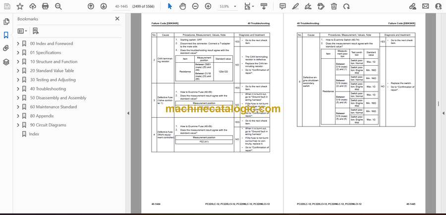