The Komatsu PC290LC-11 Crawler Excavator is a mid-size machine you’ll see on pipe jobs, bulk earthmoving, and demo where downtime burns money fast. This Shop Manual (SEN06808-15) is what most field techs and shop mechanics reach for when the fault codes don’t tell the whole story or a major component has to come apart. People usually want it to track down hydraulic or electrical issues, guide full teardown/rebuild work, and double‑check reassembly sequences before they button the machine up.
What this manual helps you do
- Trace hydraulic faults through pump, valve, and actuator circuits using the kind of schematics and step sequences shops usually rely on.
- Diagnose engine, fuel, and aftertreatment problems using the typical flowcharts, checks, and test points used on medium-horsepower diesel excavators.
- Follow disassembly and reassembly procedures for major components like swing machinery, final drives, cylinders, and travel gearboxes.
- Check electrical and electronic control issues by walking wiring routes, connector locations, and expected signal behaviors on the PC290LC-11.
- Verify adjustment and setup steps after repairs so the excavator comes back with normal performance and no repeat callbacks.
Who this is for
This manual fits a field technician, shop mechanic, or fleet manager who’s actually overseeing repairs on a Komatsu PC290LC-11 Crawler Excavator. It’s not ideal for operators just wanting daily checklists or basic controls; they’re better off with the Operation & Maintenance Manual.
FAQ
Q: Is this a searchable PDF and can I print pages for the field?
A: Yes, it’s a PDF you can search on a laptop or tablet, and you can print specific procedures to throw in the service truck.
Q: Does it go deep enough for full component rebuilds, or just light service?
A: The Komatsu PC290LC-11 Crawler Excavator Shop Manual walks through diagnostic procedures, disassembly sequences, and reference data used during workshop-level repairs.
Q: How do I know if it matches my exact PC290LC-11 variant or serial number?
A: Check your machine plate and compare to the SEN06808-15 reference; if your dealer confirms that book code for your unit, this is the right one.
Bottom line: if you’re the person actually fixing or troubleshooting a PC290LC-11, this is the manual you want; if you’re only running the machine or planning jobs, you should keep looking for the operator or planning docs instead.
📘 Show Index
Table of Contents:
- 00 Index and Foreword
- Index
- Abbreviation List
- Foreword, Safety, Basic Information
- How to Read the Shop Manual
- Safety Notice for Operation
- Precautions to Prevent Fire
- Procedures If Fire Occurs
- Precautions for Disposing of Waste Materials
- Engine Technology to Conform Exhaust Gas Emission
- Precautions for DEF
- General Character and Precautions for Handling
- Precautions for Adding
- Precautions for Storage
- Precautions for Fire Hazard and Leakage
- Other Precautions
- Store DEF
- Precautions When You Handle Hydraulic Equipment
- Precautions When You Disconnect and Connect Pipings
- Precautions When You Handle Electrical Equipment
- Precautions When You Handle Fuel System Equipment
- Precautions When You Handle Intake System Equipment
- Practical Use of KOMTRAX
- Disconnect and Connect Push-Pull Type Coupler
- How to Disconnect and Connect Type 1 Push-Pull Type Coupler
- How to Disconnect and Connect Type 2 Push-Pull Type Coupler
- How to Disconnect and Connect Type 3 Push-Pull Type Coupler
- Precautions for Disconnection and Connection of Connectors
- How to Disconnect and Connect Deutsch Connector
- How to Disconnect and Connect Slide Lock Type Connector
- How to Disconnect and Connect Connector with Lock to Pull
- How to Disconnect and Connect Connector with Lock to Push
- How to Disconnect and Connect Connector with Housing to Rotate
- How to Read the Codes for Electric Cable
- Explanation of Terms for Maintenance Standard
- Standard Tightening Torque Table
- Conversion Table
- 01 Specifications
- Table of Contents
- Specifications
- Specification Drawing
- Specification Drawing: PC290LC-11
- Working Range Drawings
- Working Range: PC290LC-11
- Specifications
- Specifications: PC290LC-11
- Weight Table
- Table of Fuel, Coolant, and Lubricants
- 10 Structure and Function
- Table of Contents
- Urea SCR System
- Layout Drawing of Urea SCR System
- Urea SCR System Diagram
- Function of Urea SCR System
- Function of DEF System
- Inducement Strategy
- Component Parts of Urea SCR System
- DEF Mixing Tube
- SCR Assembly
- DEF Tank
- DEF Pump
- DEF Injector
- DEF Hose
- DEF Tank Heating Valve
- Boot-up System
- Layout Drawing of Boot-up System
- System Operating Lamp System
- System Diagram of System Operating Lamp System
- Function of Operation Lamp System
- Battery Isolator
- Function of Battery Isolator
- Engine System
- Layout Drawing of Engine System
- Specifications of Engine System
- Function of Engine System
- Engine Control System
- System Diagram of Engine Control
- Function of Engine Control System
- Auto-Deceleration System
- System Diagram of Auto-Deceleration System
- Function of Auto-Deceleration System
- Operation of Auto-Deceleration System
- Engine Automatic Warm-up System
- System Diagram of Engine Automatic Warm-up System
- Function of Engine Automatic Warm-up System
- Overheat Prevention System
- Overheat Prevention System Diagram
- Function of Overheat Prevention System
- Turbocharger Protection System
- System Diagram of Turbocharger Protection System
- Function of Turbocharger Protection System
- Automatic Idle Stop System
- System Diagram of Automatic Idle Stop System
- Function of Automatic Idle Stop System
- Component Parts of Engine System
- VGT
- EGR System
- EGR Valve
- EGR Cooler
- KCCV System
- KCCV Ventilator
- KDPF
- Cooling System
- Layout Drawing of Cooling System
- Specifications of Cooling System
- Control System
- Layout Drawing of Control System
- Machine Monitor System
- System Diagram of Machine Monitor System
- Function of Machine Monitor System
- KomVision System
- Layout Drawing of KomVision System
- System Diagram of KomVision System
- Function of KomVision System
- KOMTRAX System
- System Diagram of KOMTRAX System
- Function of KOMTRAX System
- PPC Levers
- LH PPC Lever
- RH PPC Lever
- Automatic Grease System
- Outline of AUTO Grease System
- Component Parts of Control System
- Machine Monitor
- KomVision Controller
- KomVision Camera
- Gateway Function Controller
- Communication Terminal
- Pump Controller
- Resistor for PC-EPC Valve
- CAN Terminating Resistor
- PPC Oil Pressure Switch
- Engine Controller
- Fuel Control Dial
- Hydraulic System
- Layout Drawing of Hydraulic System
- CLSS
- Structure of CLSS
- Operation of Unload Valve and LS Pressure
- Pump Swash Plate Angle (Oil Flow) Control
- Pressure Compensation Control
- Engine and Pump Combined Control System
- Engine and Pump Combined Control System Diagram
- Function of Engine and Pump Combined Control System
- Pump and Valve Control System
- Pump and Valve Control System Diagram
- Function of Pump and Valve Control System
- Component Parts of Hydraulic System
- Hydraulic Tank
- Main Pump
- Pilot Oil Filter
- Control Valve
- Work Equipment System
- Layout Drawing of Work Equipment System
- Structure of Valve Control
- One-Touch Power Maximizing System
- System Diagram of One-Touch Power Maximizing System
- Function of One-Touch Power Maximizing System
- PPC Lock System
- System Diagram of PPC Lock
- Function of PPC Lock System
- Work Equipment and Travel Automatic Lock System
- System Diagram of Lock Lever Automatic Lock System
- Function of Work Equipment and Travel Automatic Lock System
- Operation of Lock Lever Automatic Lock System
- Attachment Oil Flow Adjuster System
- Attachment Oil Flow Adjuster System Diagram
- Function of Attachment Oil Flow Adjuster System
- Tool Control System
- Tool Control System Diagram
- Component Parts of Work Equipment System
- Work Equipment and Swing PPC Valve
- 1st-Line Attachment PPC Valve (with EPC Valve)
- 2nd-Line Attachment PPC Valve
- Solenoid Valve
- Boom Anti-drop Valve
- Arm Anti-Drop Valve
- Attachment Circuit Selector Valve (For High Pressure)
- Attachment Circuit Selector Valve (For Low Pressure)
- Attachment Bypass Solenoid Valve
- Pilot Circuit Accumulator
- Attachment Circuit Accumulator
- Swing System
- Layout Drawing of Swing System
- Swing Control System Diagram
- Function of Swing Control System
- Component Parts of Swing System
- Swing Motor
- Swing Machinery
- Swing Circle
- Travel System
- Layout Drawing of Travel System
- System Diagram of Travel Control System
- Function of Travel Control System
- Component Parts of Travel System
- Travel Motor
- Final Drive
- Travel PPC Valve
- Center Swivel Joint
- Undercarriage and Frame
- Layout Drawing of Undercarriage
- Specifications of Undercarriage
- Work Equipment
- Structure of Work Equipment
- Function of Work Equipment
- Work Equipment Clearance Adjustment Shim
- Function of Work Equipment Clearance Adjustment Shim
- Bucket Clearance Adjustment Shim
- Function of Bucket Clearance Adjustment Shim
- CAB Related Parts
- ROPS CAB
- Structure of ROPS CAB
- Function of ROPS CAB
- CAB Mount
- Structure of CAB Mount
- Function of CAB Mount
- CAB Tipping Stopper
- Structure of CAB Tipping Stopper
- Function of CAB Tipping Stopper
- 20 Standard Value Table
- Table of Contents
- Standard Value Table for Engine
- Standard Value Table for Engine: PC290LC-11
- Standard Value Table for Machine
- Standard Value Table for Machine: PC290LC-11
- Machine Posture and Procedures to Measure Performance
- Standard Value Table for Electricity
- Standard Value Table for Electricity
- 30 Testing and Adjusting
- Table of Contents
- Precautions Before Work
- Related Information on Testing and Adjusting
- Differences In Machine Monitor Symbols
- Tools for Testing and Adjusting
- Sketch of Tools for Testing and Adjusting
- Engine and Cooling System
- Examine Engine Speed
- How to Examine Engine Speed
- Examine Boost Pressure
- How to Examine Boost Pressure on Machine Monitor
- How to Examine Boost Pressure by Testing Tool
- Examine Exhaust Gas Color
- How to Examine Exhaust Gas Color with the Handy Smoke Checker
- How to Examine Exhaust Gas Color with Smoke Meter
- Examine Mass Air Flow and Temperature Sensor
- How to Examine Mass Air Flow and Temperature Sensor
- Examine and Adjust Valve Clearance
- How to Examine Valve Clearance
- How to Adjust Valve Clearance
- Examine Compression Pressure
- How to Examine Compression Pressure
- Examine Blowby Pressure
- How to Examine Blowby Pressure
- Examine Engine Oil Pressure
- How to Examine Engine Oil Pressure
- Examine EGR Valve and VGT Oil Pressure
- How to Examine EGR Valve and VGT Oil Pressure
- Examine Fuel Pressure
- How to Examine Fuel Pressure
- Examine Fuel Discharge, Return and Leakage
- How to Examine Fuel Discharge, Return, and Leakage
- Bleed Air from Fuel System
- How to Bleed Air from Fuel System
- Examine Fuel Circuit for Leakage
- How to Examine Fuel System for Leakage
- Handle Cylinder Cut-out Mode Operation
- Handle No-Injection Cranking Operation
- Examine and Adjust Air Conditioner Compressor Belt Tension
- How to Examine Air Conditioner Compressor Belt
- How to Adjust Air Conditioner Compressor Belt
- Examine Fan Belt and Alternator Belt
- How to Examine Fan Belt and Alternator Belt
- Examine Automatic Tensioner
- How to Examine Automatic Tensioner
- How to Replace Fan Belt
- Correct Soot Accumulation Correction Value by Ash Influence
- How to Correct Soot Accumulation Correction Value by Ash Influence
- Examine SCR Related Functions
- Examine DEF Pump Raised Pressure
- Examine Injection Volume from DEF Injector
- Examine DEF Line Heater Relay 1
- Examine DEF Line Heater Relay 2
- Examine DEF Pump Heater Relay
- Examine DEF Tank Heater Valve
- Examine SCR Denitration Efficiency
- Clean DEF Tank
- Bleed Air from Coolant Circuit of DEF Tank
- How to Bleed Air from Coolant Circuit of DEF Tank
- Clean DEF Pump
- Power Train
- Examine Swing Circle Bearing Clearance
- How to Examine Swing Circle Bearing Clearance
- Undercarriage and Frame
- Examine and Adjust Track Tension
- How to Examine Track Tension
- How to Adjust Track Tension
- Hydraulic System
- Release Remained Pressure in Hydraulic Circuit
- How to Release Remained Pressure from Hydraulic Circuit
- Examine and Adjust Oil Pressure in Work Equipment, Swing, and Travel Circuits
- How to Examine Oil Pressure in Work Equipment, Swing, and Travel Circuits
- How to Adjust Oil Pressure in Work Equipment, Swing, and Travel Circuits
- Examine Oil Pressure of Control Circuit
- How to Examine Oil Pressure in Control Circuit
- Examine and adjust oil pressure in pump PC control circuit
- Examine PC Valve Outlet Pressure (Servo Piston Inlet Pressure)
- Examine PC-EPC Valve Outlet Pressure
- How to Adjust Oil Pressure in Pump PC Control Circuit
- Examine and Adjust Oil Pressure in Pump LS Control Circuit
- How to Examine LS Differential Pressure with Machine Monitor
- How to Examine LS Differential Pressure by Testing Tool
- How to Examine LS Valve Outlet Pressure (Servo Piston Inlet Pressure)
- How to Examine LS-EPC Valve Outlet Pressure
- How to Adjust LS Valve
- Examine Outlet Pressure of Solenoid Valve
- How to Examine Outlet Pressure of Solenoid Valve
- Operating Condition of Solenoid Valve
- Examine PPC Valve Outlet Pressure
- How to Examine Outlet Pressure in PPC Valve
- Adjust Play of Work Equipment and Swing PPC Valves
- How to Adjust Play of Work Equipment and Swing PPC Valves
- Measure and Adjust Quick Coupler Control Valve Output Pressure
- Examine Pump Swash Plate Sensor
- How to Examine pump swash plate sensor
- Examine Parts Which Cause Hydraulic Drift of Work Equipment
- How to Examine Parts Which Cause Hydraulic Drift of Boom Cylinder and Bucket Cylinder
- How to Examine the Parts Which Cause Hydraulic Drift of Arm Cylinder
- How to Examine Parts that Cause Hydraulic Drift of PPC Valve
- Examine Oil Leakage
- How to Examine Oil Leakage from Boom Cylinder
- How to Examine Oil Leakage from Arm Cylinder
- How to Examine Oil Leakage from Bucket Cylinder
- How to Examine Oil Leakage from Swing Motor
- How to Examine Oil Leakage from Travel Motor
- Bleed Air from Hydraulic Circuit
- How to Bleed Air from Hydraulic System
- Examine and Charge Accumulator (Made by Eagle Industry Co., Ltd.) Nitrogen Gas Pressure for Attachment
- Examine Accumulator (Made by Eagle Industry Co., Ltd.) Nitrogen Gas Pressure for Attachment
- Examine and Charge Accumulator (Made by NOK) Nitrogen Gas Pressure for Attachment (Low Pressure Side)
- How to Examine Accumulator (Made by NOK) Nitrogen Gas Pressure for Attachment (Low Pressure Side)
- Examine and Charge Accumulator Nitrogen Gas Pressure for Attachment (High Pressure Side)
- How to Examine Accumulator Nitrogen Gas Pressure for Attachment (High Pressure Side)
- Replace Accumulator Bladder on High Pressure Side for Attachment Piping
- How to Replace Accumulator Bladder on High Pressure Side for Attachment Piping
- CAB Related Parts
- Examine CAB Tipping Stopper
- How to Examine Cab Tipping Stopper
- How to Adjust Mirrors
- Procedure to Adjust Machine Left Front Mirror (A)
- Procedure to Adjust Regular Position of Machine Left Front Mirror (A)
- Procedure to Adjust Machine Right Front Mirror (B)
- Procedure to Adjust Regular Position of Machine Right Front Mirror (B)
- Procedure to Adjust Machine Right Side Mirror (C)
- Electrical System
- Set and Operate Machine Monitor
- Operator Mode
- Function to Show Technician Identification Status Screen
- Function to Show Operator Identification Input Screen
- Examine Function by LCD (Liquid Crystal Display)
- Examine Function of Service Meter
- Usage Limitation and Maintenance Password Change Function
- Service Mode
- How to Operate Service Mode
- How to See Pre-defined Monitoring Information
- How to Examine Self-Define Monitor Information
- Abnormality Record Menu
- How to See Maintenance Record
- Maintenance Mode Setting
- How to Set Phone Number Entry
- Default Menu
- Diagnostic Tests Menu
- Adjustment Menu
- No-Injection Cranking Operation
- KOMTRAX Settings Menu
- How to Show Service Message
- How to Start Up KOMTRAX System
- Adjust Rearview Camera Angle
- How to Adjust Rearview Camera Angle
- Adjust KomVision Camera Angle
- How to Adjust KomVision Camera Angle
- Adjust KomVision Related Function
- Setting of KomVision (Main Setting)
- Setting of KomVision (Camera Setting)
- Setting of KomVision (Camera Calibration)
- Examine 12m Visibility on KomVision Screen
- Set Region of Bluetooth(R) Compatible Radio
- How to Set Region of Bluetooth(R) Compatible Radio
- Handle Voltage Circuit of Engine Controller
- Handle Battery Isolator Switch
- Examine Diodes
- How to Examine Diodes by Digital Tester
- How to Examine Diodes by Analog Tester
- Pm Clinic
- 40 Troubleshooting
- Table of Contents
- Precautions Before Work
- Related Information to Troubleshooting
- General Troubleshooting Points
- Troubleshooting Points for Urea SCR System
- Sequence of Events in Troubleshooting
- Checks Before Troubleshooting
- Inspection Procedure Before Troubleshooting
- Test in Accordance with Testing Procedure
- Examine Fuel Level and Type
- Examine for Impure Ingredient in Fuel
- Examine Fuel Prefilter
- Examine Water Separator, Drain Water and Sediment
- How to Replace Fuel Prefilter Cartridge
- Examine Fuel Main Filter
- Examine Water Pump for Leakage
- Examine Engine Oil Level (Oil Quantity in Oil Pan)
- Examine Coolant Level (Reservoir Tank)
- Examine Air Cleaner Clogging
- Clean Outer Element
- Replace Element
- Examine Hydraulic Oil Level
- Examine Hydraulic Oil Strainer
- Examine Hydraulic Oil Filter
- Examine Oil Level in Swing Machinery Case
- Examine Oil Level in Damper Case
- Examine Oil Level in Final Drive Case
- Bleed Air from Fuel System
- Bleed Air from Hydraulic System
- How to Examine Electric Equipment
- Automatic Grease System
- Find Malfunctions
- Malfunction Finding Procedures
- Preparation for Troubleshooting of Electrical System
- Procedure for Troubleshooting
- Symptom and Troubleshooting Numbers
- Information Shown in Troubleshooting Table
- How to Diagnose Wiring Harness for Open Circuit of Pressure Sensor System
- Connector List and Layout
- Connector Contact Connection Table
- T-Branch Box and T-Branch Adapter Table
- Fuse Location Table
- Precautions When You Clean and Replace KDPF (KCSF and KDOC)
- Prepare Short Circuit Electrical Connector (For Failure Codes [CA1883] and [CA3135])
- Failure Code Table
- Troubleshooting by Failure Code (Display of Code)
- Failure Code [6AZ0ZG]
- Failure Code [879AKA]
- Failure Code [879AKB]
- Failure Code [879BKA]
- Failure Code [879BKB]
- Failure Code [879CKA]
- Failure Code [879CKB]
- Failure Code [879DKZ]
- Failure Code [879EMC]
- Failure Code [879FMC]
- Failure Code [879GKX]
- Failure Code [989L00]
- Failure Code [989M00]
- Failure Code [989N00]
- Failure Code [A1U0N3]
- Failure Code [A1U0N4]
- Failure Code [A900FR]
- Failure Code [A900N6]
- Failure Code [A900NY]
- Failure Code [AA10NX]
- Failure Code [AB00KE]
- Failure Code [AQ10N3]
- Failure Code [AS00N3]
- Failure Code [AS00R2]
- Failure Code [AS00R3]
- Failure Code [AS00R4]
- Failure Code [AS00R5]
- Failure Code [AS00R6]
- Failure Code [AS00ZK]
- Failure Code [AS10KM]
- Failure Code [AS10NR]
- Failure Code [AS10NT]
- Failure Code [B@BAZG]
- Failure Code [B@BAZK]
- Failure Code [B@BCNS]
- Failure Code [B@BCQA]
- Failure Code [B@BCZK]
- Failure Code [B@HANS]
- Failure Code [CA115]
- Failure Code [CA122]
- Failure Code [CA123]
- Failure Code [CA131]
- Failure Code [CA132]
- Failure Code [CA144]
- Failure Code [CA145]
- Failure Code [CA153]
- Failure Code [CA154]
- Failure Code [CA187]
- Failure Code [CA221]
- Failure Code [CA222]
- Failure Code [CA227]
- Failure Code [CA234]
- Failure Code [CA238]
- Failure Code [CA239]
- Failure Code [CA249]
- Failure Code [CA256]
- Failure Code [CA271]
- Failure Code [CA272]
- Failure Code [CA322]
- Failure Code [CA323]
- Failure Code [CA324]
- Failure Code [CA325]
- Failure Code [CA331]
- Failure Code [CA332]
- Failure Code [CA343]
- Failure Code [CA351]
- Failure Code [CA352]
- Failure Code [CA356]
- Failure Code [CA357]
- Failure Code [CA386]
- Failure Code [CA428]
- Failure Code [CA429]
- Failure Code [CA435]
- Failure Code [CA441]
- Failure Code [CA442]
- Failure Code [CA449]
- Failure Code [CA451]
- Failure Code [CA452]
- Failure Code [CA488]
- Failure Code [CA515]
- Failure Code [CA516]
- Failure Code [CA553]
- Failure Code [CA555]
- Failure Code [CA556]
- Failure Code [CA559]
- Failure Code [CA595]
- Failure Code [CA687]
- Failure Code [CA689]
- Failure Code [CA691]
- Failure Code [CA692]
- Failure Code [CA697]
- Failure Code [CA698]
- Failure Code [CA731]
- Failure Code [CA778]
- Failure Code [CA1117]
- Failure Code [CA1664]
- Failure Code [CA1669]
- Failure Code [CA1673]
- Failure Code [CA1677]
- Failure Code [CA1678]
- Failure Code [CA1682]
- Failure Code [CA1683]
- Failure Code [CA1684]
- Failure Code [CA1686]
- Failure Code [CA1691]
- Failure Code [CA1694]
- Failure Code [CA1695]
- Failure Code [CA1696]
- Failure Code [CA1712]
- Failure Code [CA1713]
- Failure Code [CA1714]
- Failure Code [CA1715]
- Failure Code [CA1776]
- Failure Code [CA1777]
- Failure Code [CA1843]
- Failure Code [CA1844]
- Failure Code [CA1879]
- Failure Code [CA1881]
- Failure Code [CA1883]
- Failure Code [CA1885]
- Failure Code [CA1887]
- Failure Code [CA1921]
- Failure Code [CA1922]
- Failure Code [CA1942]
- Failure Code [CA1993]
- Failure Code [CA2185]
- Failure Code [CA2186]
- Failure Code [CA2249]
- Failure Code [CA2271]
- Failure Code [CA2272]
- Failure Code [CA2288]
- Failure Code [CA2311]
- Failure Code [CA2349]
- Failure Code [CA2353]
- Failure Code [CA2357]
- Failure Code [CA2381]
- Failure Code [CA2382]
- Failure Code [CA2383]
- Failure Code [CA2386]
- Failure Code [CA2387]
- Troubleshooting Flowchart
- Failure Code [CA2555]
- Failure Code [CA2556]
- Failure Code [CA2637]
- Failure Code [CA2639]
- Failure Code [CA2771]
- Failure Code [CA2777]
- Failure Code [CA2976]
- Failure Code [CA3133]
- Failure Code [CA3134]
- Failure Code [CA3135]
- Failure Code [CA3142]
- Failure Code [CA3143]
- Failure Code [CA3144]
- Failure Code [CA3146]
- Failure Code [CA3147]
- Failure Code [CA3148]
- Failure Code [CA3151]
- Failure Code [CA3165]
- Failure Code [CA3229]
- Failure Code [CA3231]
- Failure Code [CA3232]
- Failure Code [CA3235]
- Failure Code [CA3239]
- Failure Code [CA3241]
- Failure Code [CA3242]
- Failure Code [CA3251]
- Failure Code [CA3253]
- Failure Code [CA3254]
- Failure Code [CA3255]
- Failure Code [CA3256]
- Failure Code [CA3311]
- Failure Code [CA3312]
- Failure Code [CA3313]
- Failure Code [CA3314]
- Failure Code [CA3315]
- Failure Code [CA3316]
- Failure Code [CA3317]
- Failure Code [CA3318]
- Failure Code [CA3319]
- Failure Code [CA3321]
- Failure Code [CA3322]
- Failure Code [CA3419]
- Failure Code [CA3421]
- Failure Code [CA3497]
- Failure Code [CA3498]
- Failure Code [CA3543]
- Failure Code [CA3545]
- Failure Code [CA3547]
- Failure Code [CA3558]
- Failure Code [CA3559]
- Failure Code [CA3562]
- Failure Code [CA3563]
- Failure Code [CA3567]
- Failure Code [CA3568]
- Failure Code [CA3571]
- Failure Code [CA3572]
- Failure Code [CA3574]
- Failure Code [CA3575]
- Failure Code [CA3577]
- Failure Code [CA3578]
- Failure Code [CA3582]
- Failure Code [CA3583]
- Failure Code [CA3596]
- Failure Code [CA3649]
- Failure Code [CA3681]
- Failure Code [CA3682]
- Failure Code [CA3713]
- Failure Code [CA3717]
- Failure Code [CA3718]
- Failure Code [CA3725]
- Failure Code [CA3741]
- Failure Code [CA3748]
- Failure Code [CA3751]
- Failure Code [CA3755]
- Failure Code [CA3866]
- Failure Code [CA3867]
- Failure Code [CA3868]
- Failure Code [CA3899]
- Failure Code [CA3911]
- Failure Code [CA3912]
- Failure Code [CA3932]
- Failure Code [CA3933]
- Failure Code [CA3934]
- Failure Code [CA3935]
- Failure Code [CA3936]
- Failure Code [CA4151]
- Failure Code [CA4152]
- Failure Code [CA4155]
- Failure Code [CA4156]
- Failure Code [CA4157]
- Failure Code [CA4158]
- Failure Code [CA4159]
- Failure Code [CA4161]
- Failure Code [CA4162]
- Failure Code [CA4163]
- Failure Code [CA4164]
- Failure Code [CA4165]
- Failure Code [CA4166]
- Failure Code [CA4168]
- Failure Code [CA4169]
- Failure Code [CA4171]
- Failure Code [CA4249]
- Failure Code [CA4251]
- Failure Code [CA4259]
- Failure Code [CA4261]
- Failure Code [CA4277]
- Failure Code [CA4281]
- Failure Code [CA4459]
- Failure Code [CA4461]
- Failure Code [CA4658]
- Failure Code [CA4731]
- Failure Code [CA4732]
- Failure Code [CA4739]
- Failure Code [CA4768]
- Failure Code [CA4769]
- Failure Code [CA4842]
- Failure Code [CA4952]
- Failure Code [CA5115]
- Failure Code [CA5179]
- Failure Code [CA5181]
- Failure Code [CA5383]
- Failure Code [D110KB]
- Failure Code [D19JKZ]
- Failure Code [D811MC]
- Failure Code [D862KA]
- Failure Code [D8ALKA]
- Failure Code [D8ALKB]
- Failure Code [D8AQKR]
- Failure Code [D8G1KT]
- Failure Code [D8G6KT]
- Failure Code [DA20MC]
- Failure Code [DA22KK]
- Failure Code [DA25KP]
- Failure Code [DA26KP]
- Failure Code [DA29KQ]
- Failure Code [DA2LKA]
- Failure Code [DA2LKB]
- Failure Code [DA2QKR]
- Failure Code [DA2RKR]
- Failure Code [DAF0KM]
- Failure Code [DAF0MB]
- Failure Code [DAF0MC]
- Failure Code [DAF8KB]
- Failure Code [DAF9KQ]
- Failure Code [DAFGMC]
- Failure Code [DAFLKA]
- Failure Code [DAFLKB]
- Failure Code [DAFQKR]
- Failure Code [DAZ9KQ]
- Failure Code [DAZQKR]
- Failure Code [DB2QKR]
- Failure Code [DB2RKR]
- Failure Code [DBP0KM]
- Failure Code [DBP0KT]
- Failure Code [DBP5KB]
- Failure Code [DBP5KY]
- Failure Code [DBPQKR]
- Failure Code [DDNRKA]
- Failure Code [DDNRKY]
- Failure Code [DDNS00]
- Failure Code [DFB1KZ]
- Failure Code [DFB2KZ]
- Failure Code [DFB3L8]
- Failure Code [DFB4L8]
- Failure Code [DFB5KZ]
- Failure Code [DFB6KZ]
- Failure Code [DGH2KA]
- Failure Code [DGH2KB]
- Failure Code [DHA4KA]
- Failure Code [DHAAMA]
- Failure Code [DHACMA]
- Failure Code [DHPAMA]
- Failure Code [DHPBMA]
- Failure Code [DHS3MA]
- Failure Code [DHS4MA]
- Failure Code [DHS8MA]
- Failure Code [DHS9MA]
- Failure Code [DHSAMA]
- Failure Code [DHSBMA]
- Failure Code [DHSCMA]
- Failure Code [DHSDMA]
- Failure Code [DHSFMA]
- Failure Code [DHSGMA]
- Failure Code [DHSHMA]
- Failure Code [DHSJMA]
- Failure Code [DHX1MA]
- Failure Code [DHZAMA]
- Failure Code [DHZCL8]
- Failure Code [DKR0MA]
- Failure Code [DKR1MA]
- Failure Code [DKULKA]
- Failure Code [DKULKB]
- Failure Code [DKULKY]
- Failure Code [DR10KA]
- Failure Code [DR12KA]
- Failure Code [DR20KA]
- Failure Code [DR21KX]
- Failure Code [DR30KA]
- Failure Code [DR31KX]
- Failure Code [DR40KA]
- Failure Code [DUMBKA]
- Failure Code [DUMBKB]
- Failure Code [DV20KB]
- Failure Code [DW43KA]
- Failure Code [DW43KB]
- Failure Code [DW43KY]
- Failure Code [DW45KA]
- Failure Code [DW45KB]
- Failure Code [DW45KY]
- Failure Code [DW4CKY]
- Failure Code [DW91KA]
- Failure Code [DW91KB]
- Failure Code [DW91KY]
- Failure Code [DWA2KA]
- Failure Code [DWA2KB]
- Failure Code [DWA2KY]
- Failure Code [DWK0KA]
- Failure Code [DWK0KB]
- Failure Code [DWK0KY]
- Failure Code [DWK2KA]
- Failure Code [DWK2KB]
- Failure Code [DWK2KY]
- Failure Code [DWK8KA]
- Failure Code [DWK8KB]
- Failure Code [DWK8KY]
- Failure Code [DXA8KA]
- Failure Code [DXA8KB]
- Failure Code [DXA9KA]
- Failure Code [DXA9KB]
- Failure Code [DXE0KA]
- Failure Code [DXE0KB]
- Failure Code [DXE4KA]
- Failure Code [DXE4KB]
- Failure Code [DXE4KY]
- Failure Code [DXE5KA]
- Failure Code [DXE5KB]
- Failure Code [DXE6KA]
- Failure Code [DXE6KB]
- Failure Code [DXE7KA]
- Failure Code [DXE7KB]
- Failure Code [DXE7KY]
- Failure Code [DXE8KA]
- Failure Code [DXE8KB]
- Failure Code [DXE8KY]
- Failure Code [DXE9KA]
- Failure Code [DXE9KB]
- Failure Code [DXE9KY]
- Failure Code [DXEAKA]
- Failure Code [DXEAKB]
- Failure Code [DXEAKY]
- Failure Code [DXEKKA]
- Failure Code [DXEKKB]
- Failure Code [DXEKKY]
- Failure Code [DXELKA]
- Failure Code [DXELKB]
- Failure Code [DXELKY]
- Failure Code [DY20KA]
- Failure Code [DY20MA]
- Failure Code [DY2CKB]
- Failure Code [DY2DKB]
- Failure Code [DY2EKB]
- Failure Code [F311KA]
- Failure Code [F311KB]
- Failure Code [F312KA]
- Failure Code [F312KB]
- Failure Code [F313KA]
- Failure Code [F313KB]
- Failure Code [F314KA]
- Failure Code [F314KB]
- Failure Code [F315KB]
- Failure Code [F315KY]
- Failure Code [F316KB]
- Failure Code [F316KY]
- Failure Code [F318KB]
- Failure Code [F318KY]
- Failure Code [F31AKB]
- Failure Code [F31AKY]
- Failure Code [F31BKB]
- Failure Code [F31BKY]
- Failure Code [F31CKB]
- Failure Code [F31CKY]
- Failure Code [F31DKB]
- Failure Code [F31DKY]
- Failure Code [F31EKB]
- Failure Code [F31EKY]
- Troubleshooting of Electrical System (E-Mode)
- E-1 Engine Does Not Start (Engine Does Not Crank)
- E-2 Manual Preheating System Does Not Operate
- E-3 Automatic Preheating System Does Not Operate
- E-4 While Preheating is in Operation, Preheating Monitor Does Not Come On
- E-5 When Starting Switch is Turned to ON Position, Machine Monitor Shows Nothing
- E-6 While Starting Switch is Turned to ON Position (with Engine Stopped), Engine Oil Level Monitor Comes On in Yellow
- E-7 While Starting Switch is Turned to ON Position (with Engine Stopped), Radiator Coolant Level Monitor Comes On in Yellow
- E-8 Engine Coolant Temperature Monitor Comes On in White While Engine Runs
- E-9 Hydraulic Oil Temperature Monitor Comes On in White While Engine Runs
- E-10 Air Cleaner Clogging Monitor Comes On in Yellow While Engine Runs
- E-11 Charge Level Monitor Comes On in Red While Engine is in Operation
- E-12 Fuel Level Monitor Comes On in Red While Engine Runs
- E-13 Water Separator Monitor Comes On in Red While Engine Runs
- E-14 Engine Coolant Temperature Monitor Comes On in Red While Engine is in Operation
- E-15 Engine Oil Pressure Monitor Comes on in Red While Engine is in Operation
- E-16 Hydraulic Oil Temperature Monitor Comes On in Red While Engine is in Operation
- E-17 Fuel Gauge Display Does Not Move from Minimum or Maximum
- E-18 Display of Fuel Gauge is Different from Actual Fuel Level
- E-19 Coolant Temperature Gauge Display Does Not Move from Minimum or Maximum
- E-20 Display of Coolant Temperature Gauge is Different from Actual Coolant Temperature
- E-21 Hydraulic Oil Temperature Gauge Display Does Not Move from Minimum or Maximum
- E-22 Display of Hydraulic Oil Temperature Gauge is Different from Actual Oil Temperature
- E-23 Some Areas of Machine Monitor Screen are Not Shown
- E-24 Function Switch Does Not Operate
- E-25 Automatic Warm-up System Does Not Work (in Cold Weather)
- E-26 When Auto-Decelerator Switch is Operated, Auto-Decelerator Monitor Does Not Come On or Does Not Go Out
- E-27 Auto-Decelerator is Not Operated or Canceled with Lever
- E-28 When Working Mode Switch is Operated, Working Mode Selection Screen is Not Shown
- E-29 When Working Mode is Changed, Setting of Engine and Hydraulic Pump is Not Changed
- E-30 When Travel Speed Switch is Operated, Travel Speed Monitor Does Not Change
- E-31 When Travel Speed Selection is Changed, Actual Travel Speed Does Not Change
- E-32 Alarm Buzzer Cannot be Canceled
- E-33 Service Meter is Not Shown, While Starting Switch is in OFF Position
- E-34 Service Mode Cannot be Selected
- E-35 All of Work Equipment, Swing, and Travel Mechanism Do Not Move
- E-36 All Work Equipment, Swing and Travel Do Not Lock
- E-37 When Swing Brake Cancel Switch is Set to Cancel Position, Machine Cannot Swing
- E-38 When Swing Brake Cancel Switch is Set to Normal Position, Swing Holding Brake Does Not Operate
- E-39 One-Touch Power Maximizing Function Does Not Operate Correctly or Monitor Does Not Show
- E-40 One-Touch Power Maximizing Function is Not Cancelled
- E-41 Alarm Does Not Sound During Travel
- E-42 Alarm Does Not Stop When Machine Stops
- E-43 Horn Does Not Sound
- E-44 Horn Does Not Stop
- E-45 When Wiper Switch is Operated, Wiper Monitor Does Not Come On or Go Out
- E-46 When Wiper Switch is Operated, Windshield Wiper Does Not Operate
- E-47 Window Washer Does Not Operate When Window Washer Switch is Operated
- E-48 "Boom RAISE" is Not Shown Correctly with Monitoring Function
- E-49 "Boom LOWER" is Not Shown Correctly with Monitoring Function
- E-50 "Arm OUT" is Not Shown Correctly with Monitoring Function
- E-51 "Arm IN" is Not Shown Correctly with Monitoring Function
- E-52 "Bucket DUMP" is Not Shown Correctly with Monitoring Function
- E-53 "Bucket CURL" is Not Shown Correctly with Monitoring Function
- E-54 "Swing" is Not Shown Correctly with Monitoring Function
- E-55 "Travel" is Not Shown Correctly with Monitoring Function
- E-56 Service is Not Shown Correctly with Monitoring Function
- E-57 Attachment Hydraulic Circuit Cannot be Changed
- E-58 KOMTRAX System Does Not Operate Correctly
- Troubleshooting for Hydraulic and Mechanical Systems (H Mode)
- Information Shown in Troubleshooting Table (H-Mode)
- System Chart of Hydraulic and Mechanical Systems
- Failure Mode and Cause Table
- H-1 All Work Equipment, Swing and Travel Do Not Work
- H-2 All Work Equipment, Swing and Travel Lack Speed and Power
- H-3 Fine Control Performance or Response is Unsatisfactory
- H-4 Unusual Noise is Heard from Around Hydraulic Pump
- H-5 Engine Speed Drops Largely or Engine Stops
- H-6 Speed or Power of Boom is Low
- H-7 Arm Speed or Power is Low
- H-8 Bucket Speed or Power is Low
- H-9 Work Equipment Does Not Move in Single Operation
- H-10 Hydraulic Drift of Boom is Large
- H-11 Hydraulic Drift of Arm is Large
- H-12 Hydraulic Drift of Bucket is Large
- H-13 When Single Work Equipment is Released Hydraulically, Other Work Equipment Moves
- H-14 Time Lag of Work Equipment is Large
- H-15 One-Touch Power Maximizing Function Does Not Operate
- H-16 Attachment Circuit Cannot be Changed
- H-17 Oil Flow in Attachment Circuit Cannot be Changed
- H-18 In Mixed Operation of Work Equipment, Work Equipment with Heavier Load Moves Slower
- H-19 In Mixed Operation of Swing and Travel, Travel Speed Decreases Largely
- H-20 In Mixed Operation of Swing and Boom RAISE, Boom RAISE Speed is Low
- H-21 Machine Does Not Travel Straight
- H-22 Machine is Not Steered Correctly or Steering Power is Low
- H-23 Travel Speed is Low
- H-24 One of Tracks Does Not Run
- H-25 Travel Speed Does Not Change, or Travel Speed is Too Slow or Fast
- H-26 Upper Structure Does Not Swing to Right and Left
- H-27 Upper Structure Swings Only to Right or Left
- H-28 Swing Acceleration or Swing Speed is Low in Right and Left Directions
- H-29 Swing Acceleration or Swing Speed is Low in Only One Direction
- H-30 Upper Structure Overruns Too Much When It Stops Swing Operation (Right and Left)
- H-31 Upper Structure Overruns Too Much When It Stops Swing Operation (Only One Direction)
- H-32 Shock is Large When Upper Structure Stops Swing Operation
- H-33 There is Large Unusual Noise When It Stops Swing Operation
- H-34 Swing Drift on a Slope is Large (While Swing Parking Brake is Applied)
- H-35 Swing Drift on a Slope is Large (While Swing Parking Brake is Released)
- H-36 Quick coupler cylinder will not extend
- H-37 Quick coupler cylinder will not retract (but buzzer does not sound)
- H-38 Buzzer does not sound (but quick coupler cylinder does retract)
- H-39 Quick coupler cylinder extends and retracts slowly
- Troubleshooting of Engine (S-Mode)
- Information Shown in Troubleshooting Table (S-Mode)
- S-1 Engine Does Not Crank When Starting Switch is Turned to Start Position
- S-2 Engine Cranks but No Exhaust Smoke Comes Out
- S-3 Fuel is Injected but Engine Does Not Start (Misfiring: Engine Cranks but Does Not Start)
- S-4 Engine Startability is Unsatisfactory
- S-5 Engine Does Not Pick Up Smoothly
- S-6 Engine Stops During Operation
- S-7 Engine Runs Rough or is Not Stable
- S-8 Engine Lacks Power
- S-9 KDPF Becomes Clogged in a Short Time
- S-10 Engine Oil Consumption is Excessive
- S-11 Oil Becomes Dirty Quickly
- S-12 Fuel Consumption is Excessive
- S-13 Oil is in Coolant (or Coolant Spurts Back or Coolant Level goes Down)
- S-14 Oil Pressure Drops
- S-15 Fuel Mixes Into Engine Oil
- S-16 Water Mixes Into Engine Oil (Milky)
- S-17 Coolant Temperature Increases Too High (Overheating)
- S-18 Unusual Noise is Heard
- S-19 Vibration is Excessive
- S-20 Air Cannot be Bled from Fuel Circuit
- S-21 Active Regeneration is Done Frequently
- S-22 Active Regeneration Continues Long
- S-23 White Smoke is Exhausted During Active Regeneration
- S-24 DEF Consumption is Excessive
- S-25 There is Unusual Smell (Irritating Odor)
- S-26 Foreign Materials Enter DEF (DEF Increases)
- 50 Disassembly and Assembly
- Table of Contents
- Precautions Before Work
- Related Information on Disassembly and Assembly
- How to Read This Manual
- Coating Materials List
- Special Tool List
- Sketches of Special Tools
- Engine and Cooling System
- Remove and Install Supply Pump Assembly
- How to Remove Supply Pump Assembly
- How to Install Supply Pump Assembly
- Remove and Install Injector Assembly
- How to Remove Injector Assembly
- How to Install Injector Assembly
- Remove and Install Cylinder Head Assembly
- How to Remove Cylinder Head Assembly
- How to Install Cylinder Head Assembly
- Remove and Install EGR Valve Assembly
- How to Remove EGR Valve Assembly
- How to Install EGR Valve Assembly
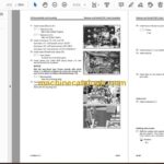
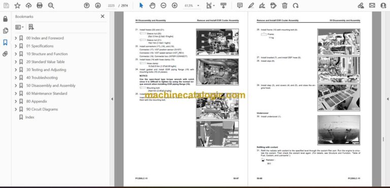
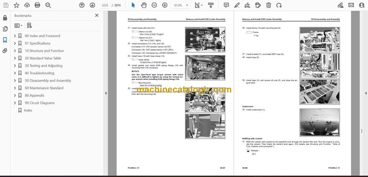
- Remove and Install EGR Cooler Assembly
- How to Remove EGR Cooler Assembly
- How to Install EGR Cooler Assembly
- Remove and Install Starter Assembly
- How to Remove Starting Motor Assembly
- How to Install Starting Motor Assembly
- Remove and Install Alternator Belt
- How to Remove Alternator Belt
- How to Install Alternator Belt
- Remove and Install Radiator Assembly
- How to Remove Radiator Assembly
- How to Install Radiator Assembly
- Remove and Install Hydraulic Oil Cooler Assembly
- How to Remove Hydraulic Oil Cooler Assembly
- How to Install Hydraulic Oil Cooler Assembly
- Remove and Install Aftercooler Assembly
- How to Remove Aftercooler Assembly
- How to Install Aftercooler Assembly
- Remove and Install Engine and Main Pump Assembly
- How to Remove Engine and Main Pump Assembly
- How to Install Engine and Main Pump Assembly
- Remove and Install Engine Front Oil Seal
- How to Remove Engine Front Oil Seal
- How to Install Engine Front Oil Seal
- Remove and Install Engine Rear Oil Seal
- How to Remove Engine Rear Oil Seal
- How to Install Engine Rear Oil Seal
- Remove and Install Fuel Cooler Assembly
- How to Remove Fuel Cooler Assembly
- How to Install Fuel Cooler Assembly
- Remove and Install Engine Hood Assembly
- How to Remove Engine Hood Assembly
- How to Install Engine Hood Assembly
- Remove and Install Fuel Tank Assembly
- How to Remove Fuel Tank Assembly
- How to Install Fuel Tank Assembly
- Remove and Install DEF Tank Assembly
- How to Remove DEF Tank Assembly
- How to Install DEF Tank Assembly
- Remove and Install DEF Tank Sensor Flange Assembly
- How to Remove DEF Tank Sensor Flange Assembly
- How to Install DEF Tank Sensor Flange Assembly
- Remove and Install DEF Tank Sensor
- How to Remove DEF Tank Sensor
- How to Install DEF Tank Sensor
- Remove and Install DEF Tank Strainer
- How to Remove DEF Tank Strainer
- How to Install DEF Tank Strainer
- Remove and Install DEF Tank Filler Port Filter
- How to Remove DEF Tank Filler Port Filter
- How to Install DEF Tank Filler Port Filter
- Remove and Install KDPF Assembly
- How to Remove KDPF Assembly
- How to Install KDPF Assembly
- Disassemble and Assemble KDPF Assembly
- How to Disassemble KDPF Assembly
- How to Assemble KDPF Assembly
- Remove and Install SCR Assembly
- How to Remove SCR Assembly
- How to Install SCR Assembly
- Remove and Install KDPF and SCR Assembly
- How to Remove KDPF and SCR Assembly
- How to Install KDPF and SCR Assembly
- Remove and Install KDPF and SCR Assembly Bracket
- How to Remove KDPF and SCR Assembly Bracket
- How to Install KDPF and SCR Assembly Bracket
- Remove and Install Bellows Pipe Assembly
- How to Remove Bellows Pipe Assembly
- How to Install Bellows Pipe Assembly
- Remove and Install KCCV Assembly
- How to Remove KCCV Assembly
- How to Install KCCV Assembly
- Remove and Install DEF Mixing Tube
- How to Remove DEF Mixing Tube
- How to Install DEF Mixing Tube
- Remove and Install DEF Injector
- How to Remove DEF Injector
- How to Install DEF Injector
- Remove and Install DEF Pump
- How to Remove DEF Pump
- How to Install DEF Pump
- Remove and Install DEF Hose
- How to Remove DEF Hose
- How to Install DEF Hose
- Remove and Install Air Cleaner Assembly
- How to Remove Air Cleaner Assembly
- How to Install Air Cleaner Assembly
- Remove and Install Air Conditioner Compressor Assembly
- How to Remove Air Conditioner Compressor Assembly
- How to Install Air Conditioner Compressor Assembly
- Remove and Install Air Conditioner Condenser Assembly
- How to Remove Air Conditioner Condenser Assembly
- How to Install Air Conditioner Condenser Assembly
- Power Train
- Remove and Install Travel Motor and Final Drive Assembly
- How to Remove Travel Motor and Final Drive Assembly
- How to Install Travel Motor and Final Drive Assembly
- Disassemble and Assemble Final Drive Assembly
- How to Disassemble Final Drive Assembly
- How to Assemble Final Drive Assembly
- Remove and Install Swing Motor and Swing Machinery Assembly
- How to Remove Swing Motor and Swing Machinery Assembly
- How to Install Swing Motor and Swing Machinery Assembly
- Disassemble and Assemble Swing Machinery Assembly
- How to Disassemble Swing Machinery Assembly
- How to Assemble Swing Machinery Assembly
- Remove and Install Swing Circle Assembly
- How to Remove Swing Circle Assembly
- How to Install Swing Circle Assembly
- Undercarriage and Frame
- Separate and Connect Track Assembly
- How to Separate Track Assembly
- How to Install Track Assembly
- Remove and Install Sprocket
- How to Remove Sprocket
- How to Install Sprocket
- Remove and Install Idler and Idler Cushion Assembly
- How to Remove Idler and Idler Cushion Assembly
- How to Install Idler and Idler Cushion Assembly
- Disassemble and Assemble Idler Assembly
- How to Disassemble Idler Assembly
- How to Assemble Idler Assembly
- Disassemble and Assemble Idler Cushion Assembly
- How to Disassemble Idler Cushion Assembly
- How to Assemble Idler Cushion Assembly
- Disassemble and Assemble Track Roller Assembly
- How to Disassemble Track Roller Assembly
- How to Assemble Track Roller Assembly
- Disassemble and Assemble Carrier Roller Assembly
- How to Disassemble Carrier Roller Assembly
- How to Assemble Carrier Roller Assembly
- Remove and Install Revolving Frame Assembly
- How to Remove Revolving Frame Assembly
- How to Install Revolving Frame Assembly
- Remove and Install Counterweight Assembly
- How to Remove Counterweight Assembly
- How to Install Counterweight Assembly
- Hydraulic System
- Remove and Install Center Swivel Joint Assembly
- How to Remove Center Swivel Joint Assembly
- How to Install Center Swivel Joint Assembly
- Disassemble and Assemble Center Swivel Joint Assembly
- How to Disassemble Center Swivel Joint Assembly
- How to Assemble Center Swivel Joint Assembly
- Remove and Install Hydraulic Tank Assembly
- How to Remove Hydraulic Tank Assembly
- How to Install Hydraulic Tank Assembly
- Remove and Install Main Pump Assembly
- How to Remove Main Pump Assembly
- How to Install Main Pump Assembly
- Remove and Install Control Valve Assembly
- How to Remove Control Valve Assembly
- How to Install Control Valve Assembly
- Disassemble and Assemble Control Valve Assembly
- How to Replace Pressure Compensation Valve Seal Ring
- How to Assemble Control Valve Assembly
- Disassemble and Assemble Work Equipment PPC Valve Assembly
- How to Disassemble Work Equipment PPC Valve Assembly
- How to Assemble Work Equipment PPC Valve Assembly
- Disassemble and Assemble Travel PPC Valve Assembly
- How to Disassemble Travel PPC Valve Assembly
- How to Assemble Travel PPC Valve Assembly
- Work Equipment
- Remove and Install Work Equipment Assembly
- How to Remove Work Equipment Assembly
- How to Install Work Equipment Assembly
- Remove and Install Boom Anti-drop Valve Assembly
- How to Remove Boom Anti-drop Valve Assembly
- How to Install Boom Anti-drop Valve Assembly
- Remove and Install Arm Anti-Drop Valve Assembly
- How to Remove Arm Anti-Drop Valve Assembly
- How to Install Arm Anti-Drop Valve Assembly
- Disassemble and Assemble Anti-Drop Valve Assembly
- How to Disassemble Anti-Drop Valve Assembly
- How to Assemble Anti-Drop Valve Assembly
- Disassemble and Assemble Work Equipment Cylinder Assembly
- How to Disassemble Work Equipment Cylinder Assembly
- How to Assemble Work Equipment Cylinder Assembly
- CAB Related Parts
- Remove and Install Operator Cab Assembly
- How to Remove Operator Cab Assembly
- How to Install Operator Cab Assembly
- Remove and Install Operator Cab Glass (Adhered Glass)
- How to Remove Operator Cab Glass (Adhered Glass)
- How to Install Operator Cab Glass (Adhered Glass)
- Remove and Install Front Window Assembly
- How to Remove Front Window Assembly
- How to Install Front Window Assembly
- Remove and Install Floor Frame Assembly
- How to Remove Floor Frame Assembly
- How to Install Floor Frame Assembly
- Remove and Install Air Conditioner Unit Assembly
- How to Remove Air Conditioner Unit Assembly
- How to Install Air Conditioner Unit Assembly
- Remove and Install Operator Seat
- How to Remove Operator Seat
- How to Install Operator Seat
- How to Remove and Install Seat Belt
- How to Remove Seat Belt
- How to Install Seat Belt
- Remove and Install Work Equipment Control Lever Assembly
- How to Remove Work Equipment Control Lever Assembly
- How to Install Work Equipment Control Lever Assembly
- Remove and Install Front Wiper Assembly
- How to Remove Front Wiper Assembly
- How to Install Front Wiper Assembly
- Electrical System
- Remove and Install Engine Controller Assembly
- How to Remove Engine Controller Assembly
- How to Install Engine Controller Assembly
- Remove and Install Pump Controller Assembly
- How to Remove Pump Controller Assembly
- How to Install Pump Controller Assembly
- Remove and Install KomVision Controller Assembly
- How to Remove KomVision Controller Assembly
- How to Install KomVision Controller Assembly
- Remove and Install Machine Monitor Assembly
- How to Remove Machine Monitor Assembly
- How to Install Machine Monitor Assembly
- Remove and Install Pump Swash Plate Sensor
- How to Remove Pump Swash Plate Sensor
- How to Install Pump Swash Plate Sensor
- Remove and Install Mass Air Flow and Temperature Sensor
- How to Remove Mass Air Flow and Temperature Sensor
- How to Install Mass Air Flow and Temperature Sensor
- Remove and Install KCCV Crankcase Pressure Sensor
- How to Remove KCCV Crankcase Pressure Sensor
- How to Install KCCV Crankcase Pressure Sensor
- Remove and Install SCR Temperature Sensor
- How to Remove SCR Temperature Sensor
- How to Install SCR Temperature Sensor
- Remove and Install KomVision Camera
- How to Remove KomVision Camera
- How to Install KomVision Camera
- Remove and Install Gateway Function Controller Assembly
- How to Remove Gateway Function Controller Assembly
- How to Install Gateway Function Controller Assembly
- Remove and Install Communication Terminal Wiring Harness
- How to Remove Communication Terminal Wiring Harness
- How to Install Communication Terminal Wiring Harness
- Remove and Install Communication Terminal
- How to Remove Communication Terminal
- How to Install Communication Terminal
- 60 Maintenance Standard
- Table of Contents
- Engine and Cooling System
- Maintenance Standard for Engine Mount
- Maintenance Standard for Cooling System
- Power Train
- Maintenance Standard for Swing Circle
- Maintenance Standard for Swing Machinery
- Maintenance Standard for Final Drive
- Maintenance Standard for Sprocket
- Maintenance Standard for Sprocket Tooth Profile Full-Scale Drawing
- Undercarriage and Frame
- Maintenance Standard for Track Frame and Idler Cushion
- Maintenance Standard for Idler
- Maintenance Standard for Track Roller
- Maintenance Standard for Carrier Roller
- Maintenance Standard for Track Shoes
- Maintenance Standard for Triple Shoes
- Hydraulic System
- Maintenance Standard for Hydraulic Tank
- Maintenance Standard for Main Pump
- Maintenance Standard for LS-EPC Valve
- Maintenance Standard for PC-EPC Valve
- Maintenance Standard for Swing Motor
- Maintenance Standard for Travel Motor
- Maintenance Standard for Control Valve
- Maintenance Standard for Boom Anti-Drop Valve
- Maintenance Standard for Arm Anti-Drop Valve
- Maintenance Standard for Work Equipment and Swing PPC Valve
- Maintenance Standard for Travel PPC Valve
- Maintenance Standard for 1st-Line Attachment PPC Valve (with EPC Valve)
- Maintenance Standard for EPC Valve of 1st-Line Attachment PPC Valve
- Maintenance Standard for 2nd-Line Attachment PPC Valve
- Maintenance Standard for Solenoid Valve
- Maintenance Standard for Attachment Circuit Selector Valve (For High Pressure)
- Maintenance Standard for Attachment Circuit Selector Valve (For Low Pressure)
- Maintenance Standard for Center Swivel Joint
- Work Equipment
- Maintenance Standard for Work Equipment Linkage
- Dimensions of Arm
- Dimensions of Bucket
- Maintenance Standard for Boom Cylinder
- Maintenance Standard for Arm Cylinder
- Maintenance Standard for Bucket Cylinder
- 80 Appendix
- Table of Contents
- Precautions Before Work
- Air Conditioner System
- Precautions for Refrigerant
- Air Conditioner Component
- Specifications of Air Conditioner
- Structure and Function of Refrigeration Cycle
- Outline of Refrigeration Cycle
- Component Parts of Air Conditioner System
- Air Conditioner Unit
- Configuration Diagram of Air Conditioner Unit
- Function of Air Conditioner Unit
- Component Parts of Air Conditioner Unit
- Function of Evaporator as Air Conditioner Unit Component
- Function of Heater Core as Air Conditioner Unit Component
- Function of Evaporator Temperature Sensor as Air Conditioner Unit Component
- Function of Servo Motor as Air Conditioner Unit Component
- Structure of Expansion Valve as Air Conditioner Unit Component
- Function of Expansion Valve as Air Conditioner Unit Component
- Operate Expansion Valve as Air Conditioner Unit Component
- Function of Dual Pressure Switch
- Air Conditioner Controller
- Structure of Air Conditioner Controller
- Compressor
- Structure of Compressor
- Specifications of Compressor
- Function of Compressor
- Condenser
- Structure of Condenser
- Specifications of Condenser
- Function of Condenser
- Air Conditioner Related Sensors
- Structure of Sunlight Sensor
- Function of Sunlight Sensor
- Structure of Outside Temperature Sensor
- Function of Outside Air Temperature Sensor
- Explanation of Procedure for Test of and Troubleshooting of Air Conditioner
- Circuit Diagram and Configuration of Connector Pins of Air Conditioner
- System Diagram of Air Conditioner
- Input and Output Signals of Air Conditioner Controller
- Function of Air Conditioner Controller
- Locations of Air Conditioner Parts and Layout of Connectors
- Examine Air Leakage (Duct)
- How to Examine Air Leakage (Duct)
- Examine Air Conditioner with Self-Diagnosis Function
- Open the Electrical System Abnormality Record Screen in Service Mode of Machine Monitor
- Examine Vent (Mode) Changeover
- How to Examine Vent (Mode) Changeover
- Examine Fresh/Recirc Air Changeover
- How to Examine Fresh/Recirc Air Changeover
- Examine Sunlight Sensor
- How to Examine Sunlight Sensor
- Examine Refrigerant (Dual) Pressure Switch
- How to Examine Refrigerant (Dual) Pressure Switch
- Examine Relay
- Air Conditioner Troubleshooting Chart 1
- Air Conditioner Troubleshooting Chart 2
- Information Shown in Troubleshooting Table
- Failure Code [879AKA]
- Failure Code [879AKB]
- Failure Code [879BKA]
- Failure Code [879BKB]
- Failure Code [879CKA]
- Failure Code [879CKB]
- Failure Code [879DKZ]
- Failure Code [879EMC]
- Failure Code [879FMC]
- Failure Code [879GKX]
- A-1 Troubleshooting for Power Supply System (Air Conditioner Does Not Operate)
- A-2 Troubleshooting for Compressor and Refrigerant System (Air is Not Cooled)
- A-3 Troubleshooting for Blower Motor System (No Air Comes Out or Air Flow is Abnormal)
- A-4 Troubleshooting for Fresh/Recirc Air Changeover
- Troubleshooting by Gauge Pressure
- Connect Service Tool
- How to Connect Service Tool
- Precautions for Disconnection and Connection of Air Conditioner Piping
- Handle Compressor Oil
- How to Replace Desiccant
- 90 Circuit Diagrams
- Table of Contents
- Hydraulic Circuit Diagram
- Symbols Used in Hydraulic Circuit Diagram
- Hydraulic Circuit Diagram (1/2)
- Hydraulic Circuit Diagram (2/2)
- Electrical Circuit Diagram
- Symbols Used in Electric Circuit Diagram
- Electrical Circuit Diagram (1/10) (Applicable Machine: 35151 to 36000)
- Electrical Circuit Diagram (2/10) (Applicable Machine: 35151 to 36000)
- Electrical Circuit Diagram (3/10) (Applicable Machine: 35151 to 36000)
- Electrical Circuit Diagram (4/10) (Applicable Machine: 35151 to 36000)
- Electrical Circuit Diagram (5/10) (Applicable Machine: 35151 to 36000)
- Electrical Circuit Diagram (6/10) (Applicable Machine: 35151 to 36000)
- Electrical Circuit Diagram (7/10) (Applicable Machine: 35151 to 36000)
- Electrical Circuit Diagram (8/10) (Applicable Machine: 35151 to 36000)
- Electrical Circuit Diagram (9/10) (Applicable Machine: 35151 to 36000)
- Electrical Circuit Diagram (10/10) (Applicable Machine: 35151 to 36000)
- Electrical Circuit Diagram (1/10) (Applicable Machine: 36001 and up)
- Electrical Circuit Diagram (2/10) (Applicable Machine: 36001 and up)
- Electrical Circuit Diagram (3/10) (Applicable Machine: 36001 and up)
- Electrical Circuit Diagram (4/10) (Applicable Machine: 36001 and up)
- Electrical Circuit Diagram (5/10) (Applicable Machine: 36001 and up)
- Electrical Circuit Diagram (6/10) (Applicable Machine: 36001 and up)
- Electrical Circuit Diagram (7/10) (Applicable Machine: 36001 and up)
- Electrical Circuit Diagram (8/10) (Applicable Machine: 36001 and up)
- Electrical Circuit Diagram (9/10) (Applicable Machine: 36001 and up)
- Electrical Circuit Diagram (10/10) (Applicable Machine: 36001 and up)
- Index
Komatsu
