These Komatsu PC300-8M2, PC300LC-8M2, PC350-8M2 crawler excavators are mid-size machines used for bulk earthmoving, trenching, loading trucks, and general construction work. The people who usually reach for a Shop Manual are field techs and workshop mechanics who actually turn spanners for a living. They’re trying to track down fault codes, strip and rebuild components, and get a down machine earning again without guessing. The SEN06931-06 shop manual is aimed at that kind of work, not just daily checks.
What this manual helps you do
- Trace hydraulic problems by following circuit diagrams and step-by-step test procedures for pumps, valves, and travel functions.
- Diagnose engine and electronic issues using wiring diagrams, connector pinouts, and what you’d expect for fault-code based troubleshooting.
- Follow teardown and reassembly sequences for major components like swing machinery, final drives, cylinders, and main control valves.
- Check adjustment procedures for things like travel, swing, and work equipment so movements are smooth and within spec.
- Handle machine setup after repairs, including bleeding systems, basic calibrations, and post-repair function checks.
Who this is for
This shop manual suits a field technician, shop mechanic, or fleet maintenance lead who’s doing proper repairs on PC300-8M2, PC300LC-8M2, or PC350-8M2 machines. If you’re just operating the excavator or only need service intervals and basic greasing points, you’d be better off with the Operation & Maintenance Manual instead.
FAQ
Q: Is this a PDF I can search and print?
A: Yes, it’s a PDF file you can search by keyword and print the pages you need for the job.
Q: Does it go deep enough for full overhauls?
A: Yes, the Komatsu PC300-8M2, PC300LC-8M2, PC350-8M2 Crawler Excavator Shop Manual walks through diagnostic procedures, disassembly sequences, and workshop-level repair steps.
Q: How do I know if it matches my exact machine version?
A: This manual is identified as SEN06931-06; you should match that book number and model designation to the info on your machine plate or dealer records.
If you’re repairing or diagnosing these specific Komatsu models in a workshop or field setting, this is the right manual; if you just need basic operation and daily service info, keep looking for the O&M book instead.
📘 Show Index
Table of Contents:
- 00 Index and Foreword
- Index
- Abbreviation List
- Foreword, Safety, Basic Information
- How to Read the Shop Manual
- Safety Notice for Operation
- Precautions to Prevent Fire
- Procedures If Fire Occurs
- Precautions When You Dispose of Waste Materials
- Precautions When You Handle Hydraulic Equipment
- Precautions When You Disconnect and Connect Pipings
- Precautions When You Handle Electrical Equipment
- Precautions When You Handle Fuel System Equipment
- Precautions When You Handle Intake System Equipment
- Practical Use of KOMTRAX
- Disconnect and Connect Push-Pull Type Coupler
- How to Disconnect and Connect Type 1 Push-Pull Type Coupler
- How to Disconnect and Connect Type 2 Push-Pull Type Coupler
- How to Disconnect and Connect Type 3 Push-Pull Type Coupler
- Precautions for Disconnection and Connection of Connectors
- How to Disconnect and Connect Deutsch Connector
- How to Disconnect and Connect Slide Lock Type Connector
- How to Disconnect and Connect Connector with Lock to Pull
- How to Disconnect and Connect Connector with Lock to Push
- How to Disconnect and Connect Connector with Housing to Rotate
- How to Read the Codes for Electric Cable
- Explanation of Terms for Maintenance Standard
- Standard Tightening Torque Table
- Conversion Table
- 01 Specifications
- Table of Contents
- Specifications
- Specification Drawing
- Specification Drawing: PC300-8M2
- Specification Drawing: PC300LC-8M2
- Specification Drawing: PC350-8M2
- Specification Drawing: PC350LC-8M2
- Specification Drawing: PC360-8M2
- Specification Drawing: PC360LC-8M2
- Working Range Drawings
- Working Range Drawings: PC300-8M2
- Working Range Drawings: PC300LC-8M2
- Working Range Drawings: PC350-8M2
- Working Range Drawings: PC350LC-8M2
- Working Range Drawings: PC360-8M2
- Working Range Drawings: PC360LC-8M2
- Specifications
- Specifications: PC300-8M2
- Specifications: PC300LC-8M2
- Specifications: PC350-8M2
- Specifications: PC350LC-8M2
- Specifications: PC360-8M2
- Specifications: PC360LC-8M2
- Weight Table
- Weight Table: PC300-8M2
- Weight Table: PC300LC-8M2
- Weight Table: PC350-8M2
- Weight Table: PC350LC-8M2
- Weight Table: PC360-8M2
- Weight Table: PC360LC-8M2
- Fuel, Coolant, Lubricant
- How to Use Fuel, Coolant and Lubricants by Ambient Temperature
- 10 Structure and Function
- Table of Contents
- Boot-up System
- Layout Drawing of Boot-up System
- System Operating Lamp System
- System Diagram of System Operating Lamp System
- Function of System Operating Lamp System
- Operation of System Operating Lamp
- Battery Disconnect Switch
- Function of Battery Disconnect Switch
- Operation of Battery Disconnect Switch
- Engine System
- Layout Drawing of Engine System
- Engine Control System
- System Diagram of Engine Control
- Operation of Engine Control System
- Auto-Deceleration System
- System Diagram of Auto-Deceleration System
- Function of Auto-Deceleration System
- Operation of Auto-Deceleration System
- Engine Automatic Warm-up System
- System Diagram of Engine Automatic Warm-up System
- Function of Engine Automatic Warm-up System
- Operation of Engine Automatic Warm-up System
- Overheat Prevention System
- Overheat Prevention System Diagram
- Function of Overheat Prevention System
- Turbocharger Protection System
- Function of Turbocharger Protection System
- Cooling System
- Layout Drawing of Cooling System
- Specifications of Cooling System
- Control System
- Layout Drawing of Control System
- Machine Monitor System
- System Diagram of Machine Monitor System
- Function of Machine Monitor System
- KOMTRAX System
- System Diagram of KOMTRAX System
- Function of KOMTRAX System
- Component Parts of Control System
- Machine Monitor
- Gateway Function Controller
- Communication Terminal
- Pump Controller
- Resistor for PC-EPC Valve
- CAN Terminating Resistor
- Engine Controller
- Fuel Control Dial
- Hydraulic System
- Layout Drawing of Hydraulic System
- CLSS
- Structure of CLSS
- Operation of Unload Valve and LS Pressure
- Pump Swash Plate Angle (Oil Flow) Control
- Pressure Compensation Control
- Engine and Pump Combined Control System
- Engine and Pump Combined Control System Diagram
- Function of Engine and Pump Combined Control System
- Pump and Valve Control System
- Pump and Valve Control System Diagram
- Function of Pump and Valve Control System
- Component Parts of Hydraulic System
- Hydraulic Tank
- Main Pump
- Control Valve
- Work Equipment System
- Layout Drawing of Work Equipment System
- One-Touch Power Maximizing System
- System Diagram of One-Touch Power Maximizing System
- Function of One-Touch Power Maximizing System
- Machine Push-up System
- Machine Push-up System Diagram
- Function of Machine Push-up System
- PPC Lock System
- System Diagram of PPC Lock
- Function of PPC Lock System
- Attachment Oil Flow Adjuster System
- Attachment Oil Flow Adjuster System Diagram
- Function of Attachment Oil Flow Adjuster System
- Component Parts of Work Equipment System
- Work Equipment and Swing PPC Valve
- 1st-Line Attachment PPC Valve (with EPC Valve)
- 2nd-Line Attachment PPC Valve
- Solenoid Valve
- Attachment Circuit Selector Valve (For High Pressure)
- Attachment Circuit Selector Valve (For Low Pressure)
- Pilot Circuit Accumulator
- Attachment Circuit Accumulator
- Swing System
- Layout Drawing of Swing System
- Swing Control System Diagram
- Function of Swing Control System
- Component Parts of Swing System
- Swing Motor
- Swing Machinery
- Swing Circle
- Travel System
- Layout Drawing of Travel System
- System Diagram of Travel Control System
- Function of Travel Control System
- Component Parts of Travel System
- Travel Motor
- Final Drive
- Travel PPC Valve
- Center Swivel Joint
- Undercarriage and Frame
- Layout Drawing of Undercarriage
- Specifications of Undercarriage
- Work Equipment
- Structure of Work Equipment
- Work Equipment Clearance Adjustment Shim
- Function of Work Equipment Clearance Adjustment Shim
- Bucket Clearance Adjustment Shim
- Function of Bucket Clearance Adjustment Shim
- CAB Related Parts
- ROPS CAB
- Structure of ROPS CAB
- Function of ROPS CAB
- CAB Mount
- Structure of CAB Mount
- Function of CAB Mount
- CAB Tipping Stopper
- Structure of CAB Tipping Stopper
- Function of CAB Tipping Stopper
- 20 Standard Value Table
- Table of Contents
- Standard Value Table for Engine
- Standard Value Table for Engine: PC300,300LC-8M2/PC350,350LC-8M2/PC360,360LC-8M2
- Standard Value Table for Machine
- Standard Value Table for Machine: PC300,300LC-8M2/PC350,350LC-8M2/PC360,360LC-8M2
- Machine Posture and Procedures to Measure Performance
- 30 Testing and Adjusting
- Table of Contents
- Precautions Before Work
- Related Information on Testing and Adjusting
- Tools for Testing and Adjusting
- Sketch of Tools for Testing and Adjusting
- Engine and Cooling System
- Examine Engine Speed
- How to Examine Engine High Idle Speed
- How to Examine Engine Low Idle Speed
- How to Examine Engine Speed at 2 Pump Relief
- Test Engine Speed at 2 Pumps Relief and One-touch Power Maximizing
- How to Examine Engine Speed with Auto-Deceleration
- Examine Boost Pressure
- How to Examine Boost Pressure on Machine Monitor
- How to Examine Boost Pressure by Testing Tool
- Examine Exhaust Gas Color
- How to Examine Exhaust Gas Color with the Handy Smoke Checker
- How to Examine Exhaust Gas Color with Smoke Meter
- Examine and Adjust Valve Clearance
- How to Examine Valve Clearance
- How to Adjust Valve Clearance
- Examine Compression Pressure
- How to Examine Compression Pressure
- Examine Blowby Pressure
- How to Examine Blowby Pressure on Machine Monitor (Machine with Blowby Pressure Sensor (OPT))
- How to Test Blowby Pressure by Testing Tool (Machine Without Blowby Pressure Sensor)
- Examine Engine Oil Pressure
- How to Examine Engine Oil Pressure
- Examine Fuel Pressure
- How to Examine Fuel Pressure
- Test Fuel Return Rate and Leakage
- How to Examine Fuel Return Rate and Leakage
- Bleed Air from Fuel System
- How to Bleed Air from Fuel System
- Examine Fuel Circuit for Leakage
- How to Examine Fuel Circuit for Leakage
- Handle Cylinder Cut-out Mode Operation
- Handle No-Injection Cranking Operation
- Examine and Adjust Air Conditioner Compressor Belt Tension
- How to Examine Air Conditioner Compressor Belt Tension
- How to Adjust Air Conditioner Compressor Belt Tension
- Power Train
- Examine Swing Circle Bearing Clearance
- How to Examine Swing Circle Bearing Clearance
- Undercarriage and Frame
- Examine and Adjust Track Tension
- How to Examine Track Tension
- How to Adjust Track Tension
- Hydraulic System
- Release Remained Pressure in Hydraulic Circuit
- How to Release Remained Pressure from Hydraulic Tank
- How to Release Remained Pressure in Hydraulic Cylinder Circuit
- How to Release Remained Pressure from Swing Motor Circuit
- How to Release Remained Pressure from Travel Motor Circuit
- Examine and Adjust Oil Pressure in Work Equipment, Swing, and Travel Circuits
- How to Examine Oil Pressure in Work Equipment, Swing, and Travel Circuits
- How to Adjust Oil Pressure in Work Equipment, Swing, and Travel Circuits
- Examine Oil Pressure of Control Circuit
- How to Examine Control Circuit Oil Pressure
- Examine and adjust oil pressure in pump PC control circuit
- How to Examine PC Valve Outlet Pressure (Servo Piston Inlet Pressure)
- How to Examine PC-EPC Valve Outlet Pressure
- How to Adjust Oil Pressure in Pump PC Control Circuit
- Examine and Adjust Oil Pressure in Pump LS Control Circuit
- How to Examine LS Differential Pressure by Testing Tool
- How to Examine LS Valve Outlet Pressure (Servo Piston Inlet Pressure)
- How to Examine LS-EPC Valve Outlet Pressure
- How to Adjust LS Valve
- Examine Outlet Pressure of Solenoid Valve
- How to Examine Outlet Pressure of Solenoid Valve
- Operating Condition of Solenoid Valve
- Examine PPC Valve Outlet Pressure
- How to Examine PPC Valve Outlet Pressure on Machine Monitor
- How to Examine PPC Valve Outlet Pressure by Testing Tool
- Adjust Play of Work Equipment and Swing PPC Valve
- How to Adjust Play of Work Equipment and Swing PPC Valve
- Examine parts which cause hydraulic drift of work equipment
- How to Examine Parts Which Cause Hydraulic Drift of Boom Cylinder and Bucket Cylinder
- How to Examine the Parts Which Cause Hydraulic Drift of Arm Cylinder
- How to Examine Parts Which Cause Hydraulic Drift of Boom Hydraulic Drift Prevention Valve
- How to Examine Parts Which Cause Hydraulic Drift of PPC Valve
- Examine Oil Leakage
- How to Examine Oil Leakage from Travel Motor
- How to Examine Oil Leakage from Swing Motor
- How to Examine Oil Leakage from Boom Cylinder
- How to Examine Oil Leakage from Arm Cylinder
- How to Examine Oil Leakage from Bucket Cylinder
- Bleed Air from Hydraulic System
- How to Bleed Air from Main Pump
- How to Bleed Air from Cylinder
- How to Bleed Air from Swing Motor
- How to Bleed Air from Travel Motor
- CAB Related Parts
- Examine CAB Tipping Stopper
- How to Examine Cab Tipping Stopper
- How to Adjust Mirrors
- Procedure to Adjust Machine Left Front Mirror (A)
- Procedure to Adjust Regular Position of Machine Left Front Mirror (A)
- Procedure to Adjust Machine Right Front Mirror (B)
- Procedure to Adjust Regular Position of Machine Right Front Mirror (B)
- Procedure to Adjust Machine Right Side Mirror (C)
- Electrical System
- Set and Operate Machine Monitor
- Operator Mode
- Function to Show Technician Identification Status Screen
- Function to Show Operator Identification Input Screen
- Examine Function by LCD (Liquid Crystal Display)
- Examine Function of Service Meter
- How to Set Usage Limitation and Change Maintenance Password
- Service Mode
- How to Operate Service Mode
- How to See Pre-defined Monitoring Information
- How to Examine Monitoring Information
- Abnormality Record Menu
- How to See Maintenance Record
- Maintenance Mode Setting
- How to Set Phone Number Entry
- Default Setting Menu
- Testing Menu
- Adjustment Menu
- No-Injection Cranking Operation
- KOMTRAX Settings Menu
- How to Show Service Message
- How to Start Up KOMTRAX System (Machine with Gateway Function Controller)
- How to Stop Use of KOMTRAX System (Machine with Gateway Function Controller)
- Adjust Rearview Camera Angle
- How to Adjust Rearview Camera Angle
- Handle Voltage Circuit of Engine Controller
- Handle Battery Disconnect Switch
- Examine Diodes
- How to Examine Diodes by Digital Tester
- How to Examine Diodes by Analog Tester
- Pm Clinic
- Pm Clinic Service
- Pm Clinic Check Sheet: PC300,300LC-8M2/PC350,350LC-8M2/PC360,360LC-8M2
- 40 Troubleshooting
- Table of Contents
- Precautions Before Work
- Related Information for Troubleshooting
- General Troubleshooting Points
- Sequence of Events in Troubleshooting
- Checks Before Troubleshooting
- Inspection Procedure Before Troubleshooting
- Walk-Around Check
- Examine Engine Related Parts
- Examine Work Equipment and Undercarriage
- Examine Electric Equipment
- Preparation for Troubleshooting of Electrical System
- Preparation for Troubleshooting of Machine Monitor
- Preparation for Troubleshooting of Engine Controller
- Preparation for Troubleshooting of Pump Controller
- Preparation for Troubleshooting of Gateway Function Controller
- How to Disconnect and Connect Connector with a Special Lock
- Disconnect and Connect Connector with Lock to Push
- How to Disconnect and Connect Deutsch Connector
- How to Disconnect and Connect BOSCH Connector
- How to Disconnect and Connect AMP Connector
- How to Disconnect and Connect SUMITOMO Connector
- How to Disconnect and Connect Connector with Lock to Pull
- How to Disconnect and Connect DELPHI Connector and PACKARD Connector
- How to Disconnect and Connect Slide Type Connector
- How to Disconnect and Connect Framatome Connector
- How to Disconnect and Connect TYCO Connector
- How to Disconnect and Connect Connector with Housing to Rotate
- Procedure for Troubleshooting
- Information Shown in Troubleshooting
- How to Diagnose Open Circuit of Hydraulic Pressure Sensor System Wiring Harness
- Connectors List
- Connector Layout
- Connector Contact Connection Table
- T-Branch Box and T-Branch Adapter Table
- Fuse Location and Connection Table
- Failure Code Table
- Troubleshooting by Failure Code (Display of Code)
- Failure Code [602KNX]
- Failure Code [879AKA]
- Failure Code [879AKB]
- Failure Code [879BKA]
- Failure Code [879BKB]
- Failure Code [879CKA]
- Failure Code [879CKB]
- Failure Code [879DKZ]
- Failure Code [879EMC]
- Failure Code [879FMC]
- Failure Code [879GKX]
- Failure Code [989L00]
- Failure Code [989M00]
- Failure Code [989N00]
- Failure Code [AA10NX]
- Failure Code [AB00KE]
- Failure Code [B@BAZG]
- Failure Code [B@BAZK]
- Failure Code [B@BCNS]
- Failure Code [B@BCQA]
- Failure Code [B@BCZK]
- Failure Code [B@HANS]
- Failure Code [CA111]
- Failure Code [CA115]
- Failure Code [CA122]
- Failure Code [CA123]
- Failure Code [CA131]
- Failure Code [CA132]
- Failure Code [CA144]
- Failure Code [CA145]
- Failure Code [CA153]
- Failure Code [CA154]
- Failure Code [CA155]
- Failure Code [CA187]
- Failure Code [CA221]
- Failure Code [CA222]
- Failure Code [CA227]
- Failure Code [CA234]
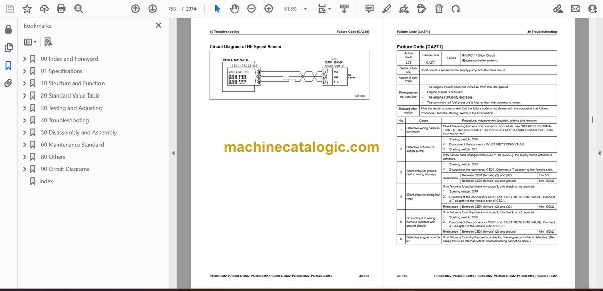
- Failure Code [CA238]
- Failure Code [CA271]
- Failure Code [CA272]
- Failure Code [CA281]
- Failure Code [CA322]
- Failure Code [CA323]
- Failure Code [CA324]
- Failure Code [CA325]
- Failure Code [CA331]
- Failure Code [CA332]
- Failure Code [CA342]
- Failure Code [CA351]
- Failure Code [CA352]
- Failure Code [CA386]
- Failure Code [CA428]
- Failure Code [CA429]
- Failure Code [CA435]
- Failure Code [CA441]
- Failure Code [CA442]
- Failure Code [CA449]
- Failure Code [CA451]
- Failure Code [CA452]
- Failure Code [CA488]
- Failure Code [CA553]
- Failure Code [CA559]
- Failure Code [CA689]
- Failure Code [CA731]
- Failure Code [CA757]
- Failure Code [CA778]
- Failure Code [CA2185]
- Failure Code [CA2186]
- Failure Code [CA2249]
- Failure Code [CA2265]
- Failure Code [CA2266]
- Failure Code [CA2311]
- Failure Code [CA2555]
- Failure Code [CA2556]
- Failure Code [D110KB]
- Failure Code [D19JKZ]
- Failure Code [D811MC]
- Failure Code [D862KA]
- Failure Code [D8ALKA]
- Failure Code [D8ALKB]
- Failure Code [D8AQKR]
- Failure Code [D8ARKR]
- Failure Code [D8G1KT]
- Failure Code [D8G6KT]
- Failure Code [DA20MC]
- Failure Code [DA22KK]
- Failure Code [DA25KP]
- Failure Code [DA26KP]
- Failure Code [DA29KQ]
- Failure Code [DA2LKA]
- Failure Code [DA2LKB]
- Failure Code [DA2QKR]
- Failure Code [DA2RKR]
- Failure Code [DAF0MB]
- Failure Code [DAF0MC]
- Failure Code [DAF8KB]
- Failure Code [DAF9KQ]
- Failure Code [DAFGMC]
- Failure Code [DAFLKA]
- Failure Code [DAFLKB]
- Failure Code [DAFQKR]
- Failure Code [DAZ9KQ]
- Failure Code [DAZQKR]
- Failure Code [DB2QKR]
- Failure Code [DDPAKA]
- Failure Code [DGH2KA]
- Failure Code [DGH2KB]
- Failure Code [DHA4KA]
- Failure Code [DHE5MA]
- Failure Code [DHPAMA]
- Failure Code [DHPBMA]
- Failure Code [DHS3MA]
- Failure Code [DHS4MA]
- Failure Code [DHS8MA]
- Failure Code [DHS9MA]
- Failure Code [DHSAMA]
- Failure Code [DHSBMA]
- Failure Code [DHSCMA]
- Failure Code [DHSDMA]
- Failure Code [DHSFMA]
- Failure Code [DHSGMA]
- Failure Code [DHSHMA]
- Failure Code [DHSJMA]
- Failure Code [DKR2MA]
- Failure Code [DKR2NX]
- Failure Code [DR21KX]
- Failure Code [DR31KX]
- Failure Code [DV20KB]
- Failure Code [DW43KA]
- Failure Code [DW43KB]
- Failure Code [DW43KY]
- Failure Code [DW45KA]
- Failure Code [DW45KB]
- Failure Code [DW45KY]
- Failure Code [DW91KA]
- Failure Code [DW91KB]
- Failure Code [DW91KY]
- Failure Code [DWA2KA]
- Failure Code [DWA2KB]
- Failure Code [DWA2KY]
- Failure Code [DWJ0KA]
- Failure Code [DWJ0KB]
- Failure Code [DWJ0KY]
- Failure Code [DWK0KA]
- Failure Code [DWK0KB]
- Failure Code [DWK0KY]
- Failure Code [DWK2KA]
- Failure Code [DWK2KB]
- Failure Code [DWK2KY]
- Failure Code [DXA8KA]
- Failure Code [DXA8KB]
- Failure Code [DXE0KA]
- Failure Code [DXE0KB]
- Failure Code [DXE4KA]
- Failure Code [DXE4KB]
- Failure Code [DXE4KY]
- Failure Code [DY20KA]
- Failure Code [DY20MA]
- Failure Code [DY2CKB]
- Failure Code [DY2DKB]
- Failure Code [DY2EKB]
- Failure Code [F313KA]
- Failure Code [F313KB]
- Failure Code [F318KB]
- Failure Code [F318KY]
- Failure Code [F@BBZL]
- Troubleshooting of Electrical System (E-Mode)
- Engine Does Not Start (Engine Does Not Crank)
- Manual Preheating System Does Not Operate
- Automatic Preheating System Does Not Operate
- While Preheating is in Operation, Preheating Monitor Does Not Come On
- When Starting Switch is Turned to ON Position, Machine Monitor Shows Nothing
- While Starting Switch is Turned to ON Position (with Engine Stopped), Engine Oil Level Caution Lamp Comes On in Yellow
- While Starting Switch is Turned to ON Position (with Engine Stopped), Radiator Coolant Level Caution Lamp Comes On in Yellow
- Engine Coolant Temperature Monitor Comes On in White While Engine is in Operation
- Hydraulic Oil Temperature Monitor Comes On in White While Engine is in Operation
- Air Cleaner Clogging Monitor Comes On in Yellow While Engine is in Operation
- Charge Level Monitor Comes On in Red While Engine is in Operation
- The fuel level monitor comes on in red while the engine is in operation.
- Water Separator Monitor Comes On in Red While Engine is in Operation
- Engine Oil Pressure Monitor Comes On in Red While Engine is in Operation
- Hydraulic oil temperature monitor comes on in red while engine is in operation.
- Fuel Gauge Does Not Move from Minimum or Maximum
- Display of Fuel Gauge is Different from Actual Fuel Level
- Engine Coolant Temperature Gauge Display Does Not Move from Minimum or Maximum
- Display of Coolant Temperature Gauge is Different from Actual Coolant Temperature
- Hydraulic Oil Temperature Gauge Does Not Move from Minimum or Maximum
- Display of Hydraulic Oil Temperature Gauge is Different from Actual Oil Temperature
- Machine Monitor Shows Incorrect Model
- Some Areas of Machine Monitor Screen are Not Shown
- Function Switch Does Not Operate
- Automatic Warm-up System Does Not Work (in Cold Weather)
- Auto-Deceleration Monitor Does Not Come On or Go Off While Auto-Deceleration Switch is Operated
- Auto-Decelerator is Not Operated or Canceled with Lever
- Working Mode Selector Screen is Not Shown While Working Mode Switch is Operated
- When Working Mode is Changed, Setting of Engine and Hydraulic Pump is Not Changed
- Travel Speed Monitor Does Not Change While Travel Speed Switch is Operated
- Travel Speed Does Not Change Even When You Operate the Operation to Change Travel Speed
- Alarm Buzzer Does Not Stop
- Service Meter is Not Shown While Starting Switch is in OFF Position
- Service Mode Cannot be Selected
- All Work Equipment, Swing, Travel Do Not Operate
- All Work Equipment, Swing, Travel Cannot be Locked
- Machine Does Not Swing While Swing Parking Brake Release Switch is Set to Release Position
- While Swing Parking Brake Release Switch is Turned on, Swing Brake is Not Operated
- One-Touch Power Maximizing Function Does Not Operate Correctly or Monitor is Not Shown
- One-Touch Power Maximizing Function is Not Cancelled
- Travel Alarm Does Not Make Sound
- Travel Alarm Does Not Stop When Machine Stops
- Horn Does Not Sound
- Horn Does Not Stop
- Wiper Monitor Does Not Come On or Go Off While Wiper Switch is Operated
- Wiper Does Not Operate When Wiper Switch is Operated
- When Window Washer Switch is Operated, Window Washer Does Not Operate
- Machine Push-up Function Cannot be Canceled
- Machine Push-up Function Does Not Operate
- Boom Raise is Not Shown Correctly with Monitoring Function
- Boom Lower is Not Shown Normally with Monitoring Function
- Arm OUT is Not Shown Correctly with Monitoring Function
- Arm IN is Not Shown Correctly with Monitoring Function
- Bucket DUMP is Not Shown Correctly with Monitoring Function
- Bucket CURL is Not Shown Correctly with Monitoring Function
- Swing is Not Shown Correctly with Monitoring Function
- Travel is Not Shown Correctly with Monitoring Function
- Service is Not Shown Correctly with Monitoring Function
- Attachment Hydraulic Circuit Cannot be Changed
- KOMTRAX System Does Not Operate Correctly
- Quick Coupler Does Not Work
- Troubleshooting for Hydraulic and Mechanical Systems (H Mode)
- Information Shown in Troubleshooting Table (H-Mode)
- All Work Equipment, Swing and Travel Do Not Work
- All Work Equipment, Swing, and Travel Lack Speed or Power
- Fine Control Performance or Response is Unsatisfactory
- Unusual Noise is Heard from Around Hydraulic Pump
- Engine Speed Drops Largely or Engine Stops
- Boom Speed or Power is Low
- Arm Speed or Power is Low
- Bucket Speed or Power is Low
- Work Equipment Does Not Move in Single Operation
- Hydraulic Drift of Boom is Large
- Hydraulic Drift of Arm is Large
- Hydraulic Drift of Bucket is Large
- When Single Work Equipment is Released Hydraulically, Other Work Equipment Moves
- Time Lag of Work Equipment is Large
- One-Touch Power Maximizing Function Does Not Operate
- Attachment Circuit Cannot be Changed
- Oil Flow in Attachment Circuit Cannot be Changed
- In Mixed Operation of Work Equipment, Work Equipment with Heavier Load Moves Slower
- In Combined Operation of Swing and Travel, Travel Speed Falls Largely
- In Combined Operation of Swing and Boom Raise, Boom Rise Speed is Low
- Machine Does Not Travel Straight
- Machine is Not Steered Well or Steering Power is Low
- Travel Speed is Low
- One of Tracks Does Not Run
- Travel Speed Does Not Change, or Travel Speed is Too Slow or Fast
- Upper Structure Does Not Swing in Two Directions of Right and Left
- Upper Structure Swings Only to the Right or Left
- Swing Acceleration or Swing Speed is Low in Two Directions of Right and Left
- Swing Acceleration Performance is Unsatisfactory or Swing Speed is Slow in Only One Direction
- Upper Structure Overruns Too Much When It Stops Swing Operation (Right and Left)
- Upper Structure Overruns Too Much When It Stops Swing Operation (Only One Direction)
- Shock is Large When Upper Structure Stops Swing Operation
- Large Unusual Noise is Heard Upper Structure Stops Swing Operation
- Swing Drift on a Slope is Large (While Swing Parking Brake is Applied)
- Swing Drift on a Slope is Large (While Swing Parking Brake is Released)
- Fan Speed is Abnormal (Too High or Low, or Does Not Move)
- Unusual Noise is Heard from Around Fan
- Troubleshooting of Engine (S-Mode)
- Information Shown in Troubleshooting Table (S-Mode)
- Engine Does Not Crank When Starting Switch is Turned to Start Position
- Engine Cranks but No Exhaust Smoke Comes Out
- Fuel is Sprayed but Engine Does Not Start (Misfiring: Engine Cranks but Does Not Start)
- Engine Startability is Unsatisfactory
- Engine Does Not Pick Up Smoothly
- Engine Stops During Operation
- Engine Does Not Rotate Smoothly
- Engine Lacks Output (or Lacks Power)
- Exhaust Smoke is Black
- Engine Oil Consumption is Excessive
- Engine Oil Becomes Dirty Quickly
- Fuel Consumption is Excessive
- Oil is in Coolant (or Coolant Spurts Back or Coolant Level Goes Down)
- Engine Oil Pressure Drops
- Fuel Mixes Into Engine Oil
- Water Mixes Into Engine Oil (Milky)
- Coolant Temperature Increases Too High (Overheat)
- Unusual Noise is Heard
- Vibration is Excessive
- Air Cannot be Bled from Fuel Circuit
- 50 Disassembly and Assembly
- Table of Contents
- Precautions Before Work
- Related Information on Disassembly and Assembly
- How to Read This Manual
- Coating Materials List
- Special Tool List
- Sketches of Special Tools
- Prepare
- Drain and Add Coolant
- How to Drain Coolant
- How to Add Coolant
- Drain and Add Hydraulic Oil
- How to Drain Hydraulic Oil
- How to Add Hydraulic Oil
- Drain and Add Fuel
- How to Drain Fuel
- How to Add Fuel
- Collect and Refill Refrigerant
- How to Collect Refrigerant
- How to Refill Refrigerant
- Engine and Cooling System
- Remove and Install Supply Pump Assembly
- How to Remove Supply Pump Assembly
- How to Install Supply Pump Assembly
- Remove and Install Cylinder Head Assembly
- How to Remove Cylinder Head Assembly
- How to Install Cylinder Head Assembly
- Remove and Install Radiator Assembly
- How to Remove Radiator Assembly
- How to Install Radiator Assembly
- Remove and Install Hydraulic Oil Cooler Assembly
- How to Remove Hydraulic Oil Cooler Assembly
- How to Install Hydraulic Oil Cooler Assembly
- Remove and Install Aftercooler Assembly
- How to Remove Aftercooler Assembly
- How to Install Aftercooler Assembly
- Remove and Install Engine and Main Pump Assembly
- How to Remove Engine and Main Pump Assembly
- How to Install Engine and Main Pump Assembly
- Remove and Install Engine Front Oil Seal
- How to Remove Engine Front Oil Seal
- How to Install Engine Front Oil Seal
- Remove and Install Engine Rear Oil Seal
- How to Remove Engine Rear Oil Seal
- How to Install Engine Rear Oil Seal
- Power Train
- Remove and Install Travel Motor and Final Drive Assembly
- How to Remove Travel Motor and Final Drive Assembly
- How to Install Travel Motor and Final Drive Assembly
- Disassemble and Assemble Final Drive Assembly
- How to Disassemble Final Drive Assembly
- How to Assemble Final Drive Assembly
- Remove and Install Swing Motor and Swing Machinery Assembly
- How to Remove Swing Motor and Swing Machinery Assembly
- How to Install Swing Motor and Swing Machinery Assembly
- Disassemble and Assemble Swing Machinery Assembly
- How to Disassemble Swing Machinery Assembly
- How to Assemble Swing Machinery Assembly
- Remove and Install Swing Circle Assembly
- How to Remove Swing Circle Assembly
- How to Install Swing Circle Assembly
- Undercarriage and Frame
- Separate and Connect Track Assembly
- How to Separate Track Assembly
- How to Install Track Assembly
- Remove and Install Sprocket
- How to Remove Sprocket
- How to Install Sprocket
- Remove and Install Idler and Idler Cushion Assembly
- How to Remove Idler and Idler Cushion Assembly
- How to Install Idler and Idler Cushion Assembly
- Disassemble and Assemble Idler Assembly
- How to Disassemble Idler Assembly
- How to Assemble Idler Assembly
- Disassemble and Assemble Idler Cushion Assembly
- How to Disassemble Idler Cushion Assembly
- How to Assemble Idler Cushion Assembly
- Disassemble and Assemble Track Roller Assembly
- How to Disassemble Track Roller Assembly
- How to Assemble Track Roller Assembly
- Disassemble and Assemble Carrier Roller Assembly
- How to Disassemble Carrier Roller Assembly
- How to Assemble Carrier Roller Assembly
- Remove and Install Revolving Frame Assembly
- How to Remove Revolving Frame Assembly
- How to Install Revolving Frame Assembly
- Remove and Install Counterweight Assembly
- How to Remove Counterweight Assembly
- How to Install Counterweight Assembly
- Hydraulic System
- Remove and Install Center Swivel Joint Assembly
- How to Remove Center Swivel Joint Assembly
- How to Install Center Swivel Joint Assembly
- Disassemble and Assemble Center Swivel Joint Assembly
- How to Disassemble Center Swivel Joint Assembly
- How to Assemble Center Swivel Joint Assembly
- Remove and Install Hydraulic Tank Assembly
- How to Remove Hydraulic Tank Assembly
- How to Install Hydraulic Tank Assembly
- Remove and Install Main Pump Assembly
- How to Remove Main Pump Assembly
- How to Install Main Pump Assembly
- Remove and Install Control Valve Assembly
- How to Remove Control Valve Assembly
- How to Install Control Valve Assembly
- Disassemble and Assemble Control Valve Assembly
- How to Replace Pressure Compensation Valve Seal Ring
- How to Assemble Control Valve Assembly
- Disassemble and Assemble Work Equipment PPC Valve Assembly
- How to Disassemble Work Equipment PPC Valve Assembly
- How to Assemble Work Equipment PPC Valve Assembly
- Disassemble and Assemble Travel PPC Valve Assembly
- How to Disassemble Travel PPC Valve Assembly
- How to Assemble Travel PPC Valve Assembly
- Work Equipment
- Remove and Install Work Equipment Assembly
- How to Remove Work Equipment Assembly
- How to Install Work Equipment Assembly
- Disassemble and Assemble Work Equipment Cylinder Assembly
- How to Disassemble Work Equipment Cylinder Assembly
- How to Assemble Work Equipment Cylinder Assembly
- CAB Related Parts
- Remove and Install Operator Cab Assembly
- How to Remove Operator Cab Assembly
- How to Install Operator Cab Assembly
- Remove and Install Operator Cab Glass (Adhered Glass)
- How to Remove Operator Cab Glass (Adhered Glass)
- How to Install Operator Cab Glass (Adhered Glass)
- Remove and Install Front Window Assembly
- How to Remove Front Window Assembly
- How to Install Front Window Assembly
- Remove and Install Floor Frame Assembly
- How to Remove Floor Frame Assembly
- How to Install Floor Frame Assembly
- Remove and Install Air Conditioner Unit Assembly
- How to Remove Air Conditioner Unit Assembly
- How to Install Air Conditioner Unit Assembly
- Remove and Install Operator Seat
- How to Remove Operator Seat
- How to Install Operator Seat
- How to Remove and Install Seat Belt
- How to Remove Seat Belt
- How to Install Seatbelt
- Remove and Install Front Wiper Assembly
- How to Remove Front Wiper Assembly
- How to Install Front Wiper Assembly
- Electrical System
- Remove and Install Engine Controller Assembly
- How to Remove Engine Controller Assembly
- How to Install Engine Controller Assembly
- Remove and Install Pump Controller Assembly
- How to Remove Pump Controller Assembly
- How to Install Pump Controller Assembly
- Remove and Install Machine Monitor Assembly
- How to Remove Machine Monitor Assembly
- How to Install Machine Monitor Assembly
- Remove and Install Gateway Function Controller Assembly
- How to Remove Gateway Function Controller Assembly
- How to Install Gateway Function Controller Assembly
- Remove and Install Communication Terminal Wiring Harness
- How to Remove Communication Terminal Wiring Harness
- How to Install Communication Terminal Wiring Harness
- Remove and Install Communication Terminal
- How to Remove Communication Terminal
- How to Install Communication Terminal
- 60 Maintenance Standard
- Table of Contents
- Explanation of Terms for Maintenance Standard
- Engine and Cooling System
- Maintenance Standard for Engine Mount
- Maintenance Standard for Cooling System
- Power Train
- Maintenance Standard for Swing Circle
- Maintenance Standard for Swing Machinery
- Maintenance Standard for Final Drive
- Maintenance Standard for Sprocket
- Maintenance Standard for Sprocket Tooth Profile Full-Scale Drawing
- Undercarriage and Frame
- Maintenance Standard for Track Frame and Idler Cushion
- Maintenance Standard for Idler
- Maintenance Standard for Track Roller
- Maintenance Standard for Carrier Roller
- Maintenance Standard for Track Shoes
- Maintenance Standard for Triple Shoes
- Hydraulic System
- Maintenance Standard for Hydraulic Tank
- Maintenance Standard for Main Pump
- Maintenance Standard for Swing Motor
- Maintenance Standard for Travel Motor
- Maintenance Standard for Control Valve
- Maintenance Standard for Work Equipment and Swing PPC Valve
- Maintenance Standard for Travel PPC Valve
- Maintenance Standard for 1st-Line Attachment PPC Valve (with EPC Valve)
- Maintenance Standard for EPC Valve of 1st-Line Attachment PPC Valve
- Maintenance Standard for 2nd-Line Attachment PPC Valve
- Maintenance Standard for Solenoid Valve
- Maintenance Standard for Attachment Circuit Selector Valve (For High Pressure)
- Maintenance Standard for Attachment Circuit Selector Valve (For Low Pressure)
- Maintenance Standard for Center Swivel Joint
- Work Equipment
- Maintenance Standard for Work Equipment Linkage
- Dimensions of Arm
- Dimensions of Bucket
- Maintenance Standard for Boom Cylinder
- Maintenance Standard for Arm Cylinder
- Maintenance Standard for Bucket Cylinder
- 80 Others
- Table of Contents
- Precautions Before Work
- Air Conditioner System
- Precautions for Refrigerant
- Layout Drawing of Air Conditioner System
- Specifications of Air Conditioner
- Structure of Refrigeration Cycle
- Function of Refrigeration Cycle
- System Diagram of Air Conditioner
- Component Parts of Air Conditioner System
- Air Conditioner Unit
- Structure of Air Conditioner Unit
- Function of Air Conditioner Unit
- Component Parts of Air Conditioner Unit
- Air Conditioner Controller
- Structure of Air Conditioner Controller
- Function of Air Conditioner Controller
- Input and Output Signals of Air Conditioner Controller
- Compressor
- Structure of Compressor
- Specifications of Compressor
- Function of Compressor
- Operation of Compressor
- Condenser
- Structure of Condenser
- Specifications of Condenser
- Function of Condenser
- Air Conditioner Related Sensors
- Structure of Sunlight Sensor
- Function of Sunlight Sensor
- Structure of Outside Temperature Sensor
- Function of Outside Air Temperature Sensor
- Circuit Diagram and Configuration of Connector Pins of Air Conditioner
- Locations of Air Conditioner Parts and Layout of Connectors
- Examine Air Leakage (Duct Connection)
- How to Examine Air Leakage (Duct Connection)
- Examine Air Conditioner with Self-Diagnosis Function
- Examine Vent (Mode) Changeover
- How to Examine Vent (Mode) Changeover
- Examine Fresh/Recirc Air Changeover
- How to Examine Fresh/Recirc Air Changeover
- Examine Sunlight Sensor
- How to Examine Sunlight Sensor
- Examine Dual Pressure Switch
- How to Examine Dual Pressure Switch
- Examine Relay
- Simple Check of Refrigerant Level Through Sight Glass
- Procedure for Troubleshooting of Air Conditioner
- Information Shown in Troubleshooting Table
- Failure Code [879AKA]
- Failure Code [879AKB]
- Failure Code [879BKA]
- Failure Code [879BKB]
- Failure Code [879CKA]
- Failure Code [879CKB]
- Failure Code [879DKZ]
- Failure Code [879EMC]
- Failure Code [879FMC]
- Failure Code [879GKX]
- Air Conditioner Does Not Operate
- Defective Cooling
- Heater Does Not Operate
- Cool Air Does Not Come Out
- No Air Comes Out or Air Flow is Abnormal
- Fresh/Recirc Air Changeover Does Not Work
- Connect Service Tool
- How to Connect Service Tool
- Precautions for Disconnection and Connection of Air Conditioner Piping
- Handle Compressor Oil
- How to Replace Desiccant
- 90 Circuit Diagrams
- Table of Contents
- How to Read the Codes for Electric Cable
- Hydraulic Circuit Diagram
- Symbols Used in Hydraulic Circuit Diagram
- Hydraulic Circuit Diagram
- Electrical Circuit Diagram
- Symbols Used in Electric Circuit Diagram
- Electrical Circuit Diagram (1/6)
- Electrical Circuit Diagram (2/6)
- Electrical Circuit Diagram (3/6)
- Electrical Circuit Diagram (4/6)
- Electrical Circuit Diagram (5/6)
- Electrical Circuit Diagram (6/6)
- Index
Komatsu


