These Komatsu PC30MR-5, PC30MR-5E1, PC35MR-5 Crawler Excavators are compact machines that spend their lives trenching, loading trucks, working tight sites, and doing utility and landscaping work. The Shop Manual is what your dealer tech or in-house mechanic reaches for when the machine is down or a major component needs work. People usually want this manual to cut diagnostic time, plan repairs around parts availability, and keep machines turning hours instead of sitting in the yard.
What this manual helps you do
- Trace hydraulic issues on the PC30MR-5 / PC30MR-5E1 / PC35MR-5 using factory test points and step-by-step fault-finding logic.
- Diagnose engine, fuel, and electrical faults with wiring information and guided checks so you’re not guessing or just swapping parts.
- Follow teardown and reassembly sequences for major components like travel motors, swing machinery, cylinders, and final drives.
- Check adjustment procedures for things like travel straightness, swing functions, and pilot controls after component replacement.
- Handle scheduled workshop-level maintenance tasks with the same methods a Komatsu dealer shop would use.
Who this is for
This Shop Manual suits field techs, shop mechanics, and fleet managers who schedule and supervise real repairs, not just daily checks. If you’re an operator looking for basic greasing points and warning light meanings, you want the Operation & Maintenance manual instead.
FAQ
Q: Is this a PDF I can search and print?
A: Yes, this is a PDF manual you can search by keyword and print sections for use in the shop.
Q: Is it detailed enough for full component rebuilds?
A: The Komatsu PC30MR-5, PC30MR-5E1, PC35MR-5 Crawler Excavator Shop Manual walks through diagnostic procedures, disassembly sequences, and workshop-level checks used during major repairs.
Q: How do I know if it matches my exact machine variant?
A: You’ll want to match your machine model and book reference YEBM202700-00 against your serial tag or dealer info to confirm coverage.
Bottom line: If you’re planning or performing real repairs on these Komatsu minis, this is the right manual; if you just need operating tips and daily service, keep looking for the O&M book instead.
📘 Show Index
Table of Contents:
- 00 Index and Foreword
- Index
- Abbreviation List
- Foreword, Safety, Basic Information
- How to Read the Shop Manual
- Safety Notice for Operation
- Precautions to Prevent Fire
- Procedures If Fire Occurs
- Precautions When You Discard Waste Materials
- Precautions When You Handle Hydraulic Equipment
- Precautions When You Disconnect and Connect Pipings
- Precautions When You Handle Electrical Equipment
- Precautions When You Handle Fuel System Equipment
- Precautions When You Handle Intake System Equipment
- Practical Use of KOMTRAX
- Disconnect and Connect Push-Pull Type Coupler
- How to Disconnect and Connect Type 1 Push-Pull Type Coupler
- How to Disconnect and Connect Type 2 Push-Pull Type Coupler
- How to Disconnect and Connect Type 3 Push-Pull Type Coupler
- Precautions for Disconnection and Connection of Connectors
- How to Disconnect and Connect Deutsch Connector
- How to Disconnect and Connect Slide Lock Type Connector
- How to Disconnect and Connect Connector with Lock to Pull
- How to Disconnect and Connect Connector with Lock to Push
- How to Disconnect and Connect Connector with Housing to Rotate
- How to Read the Codes for Electric Cable
- Explanation of Terms for Maintenance Standard
- Standard Tightening Torque Table
- Conversion Table
- 01 Specifications
- Table of Contents
- Abbreviation List
- Specifications
- Specification Drawing
- Specification Drawing: PC30MR-5 (Serial Number: 50001 to 64000)
- Specification Drawing: PC30MR-5 (Serial Number: 64001 and up)
- Specification Drawing: PC30MR-5E1
- Specification Drawing: PC35MR-5 (Serial Number: 30001 to 35000)
- Specification Drawing: PC35MR-5 (Serial Number: 35001 and up)
- Specification Drawing: PC35MR-5E1
- Working Range Drawings
- Working Range Drawings: PC30MR-5 (Serial Number: 50001 to 64000)
- Working Range Drawings: PC30MR-5 (Serial Number: 64001 and up)
- Working Range Drawings: PC30MR-5E1
- Working Range Drawings: PC35MR-5 (Serial Number: 30001 to 35000)
- Working Range Drawings: PC35MR-5 (Serial Number: 35001 and up)
- Working Range Drawings: PC35MR-5E1
- Specifications
- Specifications: PC30MR-5 (Serial Number: 50001 to 64000)
- Specifications: PC30MR-5 (Serial Number: 64001 and up)
- Specifications: PC30MR-5E1
- Specifications: PC35MR-5 (Serial Number: 30001 to 35000)
- Specifications: PC35MR-5 (Serial Number: 35001 and up)
- Specifications: PC35MR-5E1
- Weight Table
- Weight Table: PC30MR-5 (Serial Number: 50001 to 64000)
- Weight Table: PC30MR-5 (Serial Number: 64001 and up)
- Weight Table: PC30MR-5E1
- Weight Table: PC35MR-5 (Serial Number: 30001 to 35000)
- Weight Table: PC35MR-5 (Serial Number: 35001 and up)
- Weight Table: PC35MR-5E1
- Table of Fuel, Coolant, and Lubricants
- 10 Structure and Function
- Table of Contents
- Abbreviation List
- Boot-up System
- Layout Drawing of Boot-up System
- System Operating Lamp System
- System Diagram of System Operating Lamp System
- Function of Operation Lamp System
- Quick Release Battery Terminal (-)
- Function of Quick Release Battery Terminal (-)
- Battery Disconnect Switch
- Function of Battery Disconnect Switch
- Engine System
- Layout Drawing of Engine System
- Engine Control System
- System Diagram of Engine Control
- Function of Engine Control System
- Auto-Deceleration System
- System Diagram of Auto-Deceleration System
- Function of Auto-Deceleration System
- Operation of Auto-Deceleration System
- Overheat Prevention System
- Overheat Prevention System Diagram
- Function of Overheat Prevention System
- Automatic Idle Stop System
- System Diagram of Automatic Idle Stop System
- Function of Automatic Idle Stop System
- Component Parts of Engine System
- Cooling System
- Layout Drawing of Cooling System
- Specifications of Cooling System
- Control System
- Layout Drawing of Control System
- Machine Monitor System
- System Diagram of Machine Monitor System
- KOMTRAX System
- System Diagram of KOMTRAX System
- Function of KOMTRAX System
- Component Parts of Control System
- Machine Monitor
- KOMTRAX Terminal
- Machine Controller
- Resistor for PC-EPC Valve
- Fuel Control Dial
- Hydraulic System
- Layout Drawing of Hydraulic System
- CLSS
- Structure of CLSS
- Function of CLSS
- Engine and Pump Combined Control System
- Engine and Pump Combined Control System Diagram
- Function of Engine and Pump Combined Control System
- Component Parts of Hydraulic System
- Hydraulic Tank
- Main Pump
- Control Valve
- Work Equipment System
- Layout Drawing of Work Equipment System
- Structure of Valve Control
- PPC Lock System
- System Diagram of PPC Lock
- Function of PPC Lock System
- Work Equipment and Travel Automatic Lock System
- Function of Work Equipment and Travel Automatic Lock System
- Operation of Lock Lever Automatic Lock System
- Attachment Oil Flow Adjuster System
- Attachment Oil Flow Adjuster System Diagram
- Function of Attachment Oil Flow Adjuster System
- Component Parts of Work Equipment System
- Work Equipment and Swing PPC Valve
- Attachment PPC Valve
- Blade PPC Valve
- Boom Swing PPC Valve
- Bipartite Solenoid Valve
- Multi-Control Valve
- Pilot Circuit Accumulator
- Swing System
- Layout Drawing of Swing System
- Component Parts of Swing System
- Swing Motor
- Swing Machinery
- Swing Circle
- Travel System
- Layout Drawing of Travel System
- System Diagram of Travel Control System
- Function of Travel Control System
- Component Parts of Travel System
- Travel Motor
- Travel PPC Valve
- Center Swivel Joint
- Undercarriage and Frame
- Layout Drawing of Undercarriage
- Specifications of Undercarriage
- Idler Cushion
- Structure of Idler Cushion
- Specifications of Idler Cushion
- Work Equipment
- Structure of Work Equipment
- Function of Work Equipment
- Work Equipment Clearance Adjustment Shim
- Function of Work Equipment Clearance Adjustment Shim
- CAB Related Parts
- ROPS CAB
- Structure of ROPS CAB
- Function of ROPS CAB
- Tilt Type Floor
- Structure of Tilt Type Floor
- Function of Tilt Type Floor
- 20 Standard Value Table
- Table of Contents
- Abbreviation List
- Standard Value Table for Engine
- Standard Value Table for Engine: PC30MR-5
- Standard Value Table for Engine: PC30MR-5E1
- Standard Value Table for Engine: PC35MR-5
- Standard Value Table for Engine: PC35MR-5E1
- Standard Value Table for Machine
- Standard Value Table for Machine: PC30MR-5
- Standard Value Table for Machine: PC30MR-5E1
- Standard Value Table for Machine: PC35MR-5
- Standard Value Table for Machine: PC35MR-5E1
- Machine Posture and Procedures to Measure Performance
- 30 Testing and Adjusting
- Table of Contents
- Precautions Before Work
- Abbreviation List
- Related Information on Testing and Adjusting
- Differences In Machine Monitor Symbols
- Tools for Testing and Adjusting
- Sketch of Tools for Testing and Adjusting
- Engine and Cooling System
- Examine Engine Speed
- How to Examine Engine Speed
- Examine Exhaust Gas Color
- How to Examine Exhaust Gas Color with the Handy Smoke Checker
- How to Examine Exhaust Gas Color with Smoke Meter
- Examine and Adjust Valve Clearance
- How to Examine Valve Clearance
- How to Adjust Valve Clearance
- Examine Compression Pressure
- How to Examine Compression Pressure
- Examine Engine Oil Pressure
- How to Examine Engine Oil Pressure
- Examine and Adjust Fuel Injection Timing
- How to Examine Fuel Injection Timing
- How to Adjust Fuel Injection Timing
- Bleed Air from Fuel System
- How to Bleed Air from Fuel System
- Examine Fuel Circuit for Leakage
- How to Examine Fuel System for Leakage
- Examine and Adjust Alternator Belt Tension
- How to Examine Alternator Belt Tension
- How to Adjust Alternator Belt Tension
- Examine and Adjust Air Conditioner Compressor Belt Tension
- How to Examine Air Conditioner Compressor Belt Tension
- How to Adjust Air Conditioner Compressor Belt Tension
- Power Train
- Examine Swing Circle Bearing Clearance
- How to Examine Swing Circle Bearing Clearance
- Undercarriage and Frame
- Examine and Adjust Track Tension
- How to Examine Track Tension
- How to Adjust Track Tension
- Hydraulic System
- Release Remained Pressure in Hydraulic Circuit
- How to Release Remained Pressure from Hydraulic Tank
- How to Release Remained Pressure in PPC Accumulator Circuit
- How to Release Remained Pressure in Hydraulic Cylinder Circuit
- How to Release Remained Pressure from Swing Motor Circuit
- How to Release Remained Pressure from Travel Motor Circuit
- Examine and Adjust Oil Pressure in Work Equipment, Travel, and Boom Swing Circuits
- How to Examine Oil Pressure in Work Equipment, Travel, and Boom Swing Circuits
- How to Adjust Oil Pressure in Work Equipment, Travel, and Boom Swing Circuits
- Examine and Adjust Swing and Blade Circuit Oil Pressure
- How to Examine Oil Pressure in Swing and Blade Circuits
- How to Adjust Oil Pressure in Swing and Blade Circuits
- Examine and Adjust Oil Pressure in Control Circuit
- How to Examine Oil Pressure in Control Circuit
- How to Adjust Oil Pressure in Control Circuit
- Adjust Oil Pressure in Pump PC Control Circuit
- How to Adjust Oil Pressure in Pump PC Control Circuit
- Examine and Adjust Oil Pressure in Pump LS Control Circuit
- How to Examine LS Differential Pressure with Machine Monitor
- How to Examine LS Differential Pressure by Testing Tool
- How to Adjust LS Valve
- Examine Outlet Pressure of Solenoid Valve
- How to Examine Outlet Pressure of Solenoid Valve by Machine Monitor
- How to Examine Outlet Pressure of Solenoid Valve by Testing Tool
- Operating Condition of Solenoid Valve
- Examine PPC Valve Outlet Pressure
- How to Examine Outlet Pressure of PPC Valve with Machine Monitor
- How to Examine Outlet Pressure of PPC Valve by Testing Tool
- Adjust Play of Work Equipment and Swing PPC Valves
- How to Adjust Play of Work Equipment and Swing PPC Valves
- Examine Swing Parking Brake Release Pressure
- How to Examine Swing Parking Brake Release Pressure
- Examine and Adjust Travel Deviation
- How to Examine Travel Deviation
- How to Adjust Travel Deviation
- Examine Parts Which Cause Hydraulic Drift of Work Equipment
- How to Examine Parts Which Cause Hydraulic Drift of Boom Cylinder and Bucket Cylinder
- How to Examine the Parts Which Cause Hydraulic Drift of Arm Cylinder
- How to Examine Parts that Cause Hydraulic Drift of PPC Valve
- Examine Oil Leakage
- How to Examine Oil Leakage from Boom Cylinder
- How to Examine Oil Leakage from Arm Cylinder
- How to Examine Oil Leakage from Bucket Cylinder
- How to Examine Oil Leakage from Blade Cylinder
- Bleed Air from Hydraulic Circuit
- How to Bleed Air from Hydraulic System
- Pressurize Hydraulic Tank
- How to Pressurize Hydraulic Tank
- CAB Related Parts
- Open and Close Floor Unit
- Procedure to Open Floor Unit
- Procedure to Close Floor Unit
- Electrical System
- Set and Operate Machine Monitor
- Operator Mode
- Examine Function by LCD (Liquid Crystal Display)
- Examine Function of Service Meter
- Usage Limitation and Maintenance Password Change Function
- Service Mode
- How to Operate Service Mode
- How to See Pre-defined Monitoring Information
- How to Examine Self-Define Monitor Information
- Abnormality Record Menu
- How to See Maintenance Record
- Maintenance Mode Setting
- How to Set Phone Number Entry
- Default Menu
- Adjustment Menu
- How to Operate Battery Disconnect Switch Setting
- KOMTRAX Settings Menu
- How to Show Service Message
- How to Start Up KOMTRAX Terminal
- Handle Voltage Circuit of Engine Controller
- Handle Quick Release Battery Terminal (-)
- Handle Battery Disconnect Switch
- Examine Diodes
- How to Examine Diodes by Digital Tester
- How to Examine Diodes by Analog Tester
- Pm Clinic
- Pm Clinic Service
- Pm Clinic Check Sheet: PC30MR-5
- Pm Clinic Check Sheet: PC30MR-5E1
- Pm Clinic Check Sheet: PC35MR-5
- Pm Clinic Check Sheet: PC35MR-5E1
- 40 Troubleshooting
- Table of Contents
- Precautions Before Work
- Abbreviation List
- Related Information to Troubleshooting
- General Troubleshooting Points
- Sequence of Events in Troubleshooting
- Inspection Before Troubleshooting
- Inspection Procedure Before Troubleshooting
- Test in Accordance with Testing Procedure
- Examine Fuel Level and Type
- Examine Water Separator, Drain Water and Sediment
- Examine Fuel Main Filter Cartridge
- Examine Engine Oil Level (Oil Quantity in Oil Pan)
- Examine Coolant Level (Reservoir Tank)
- Examine Air Cleaner Clogging
- Clean Outer Element (Single Element)
- Replace Single Element
- Examine Hydraulic Oil Level
- Examine Hydraulic Oil Strainer
- Examine Hydraulic Oil Filter
- Examine Oil Level in Final Drive Case
- Bleed Air from Fuel System
- Bleed Air from Hydraulic System
- How to Examine Electrical Components
- Preparation for Troubleshooting of Electrical System
- Procedure for Troubleshooting
- Symptom and Troubleshooting Numbers
- Information Shown in Troubleshooting Table
- Connector List and Layout
- Connector Contact Connection Table
- Connector Contact Identification (For 3D88E-7 Engine)
- T-Branch Box and T-Branch Adapter Table
- Fuse Location Table
- Failure Code Table
- Troubleshooting by Failure Code (Display of Code)
- Failure Code [989L00]
- Failure Code [989M00]
- Failure Code [989N00]
- Failure Code [B@BCNS]
- Failure Code [D19JKZ]
- Failure Code [D19JKZ]
- Failure Code [D811MC]
- Failure Code [D862KA]
- Failure Code [D8ALKA]
- Failure Code [D8ALKB]
- Failure Code [D8AQKR]
- Failure Code [DAF0KT]
- Failure Code [DAF0MB]
- Failure Code [DAF0MC]
- Failure Code [DAF3KK]
- Failure Code [DAF9KQ]
- Failure Code [DAFGMC]
- Failure Code [DAFLKA]
- Failure Code [DAFLKB]
- Failure Code [DAFQKR]
- Failure Code [DB2QKR]
- Failure Code [DBH0MC]
- Failure Code [DBH2KK]
- Failure Code [DBH2KK]
- Failure Code [DBH5KP]
- Failure Code [DBH5KP]
- Failure Code [DBH9KQ]
- Failure Code [DBHLKA]
- Failure Code [DBHLKB]
- Failure Code [DBHQKR]
- Failure Code [DBHQKR]
- Failure Code [DDNRKA]
- Failure Code [DDNRKY]
- Failure Code [DDNS00]
- Failure Code [DDWLKA]
- Failure Code [DDWLKB]
- Failure Code [DFB1KZ]
- Failure Code [DFB3L8]
- Failure Code [DFB5KZ]
- Failure Code [DHS1MA]
- Failure Code [DHS5MA]
- Failure Code [DKULKA]
- Failure Code [DKULKB]
- Failure Code [DKULKY]
- Failure Code [DV00KB]
- Failure Code [DV20KB]
- Failure Code [DW43KA]
- Failure Code [DW43KB]
- Failure Code [DW43KY]
- Failure Code [DW4CKY]
- Failure Code [DXA8KA]
- Failure Code [DXA8KB]
- Failure Code [DXE7KA]
- Failure Code [DXE7KB]
- Failure Code [DXE7KY]
- Failure Code [DXEAKA]
- Failure Code [DXEAKB]
- Failure Code [DXEAKY]
- Troubleshooting of Electrical System (E-Mode)
- E-1 Engine Does Not Start (Engine Does Not Crank)
- E-2 Engine Does Not Start (Engine Does Not Crank)
- E-3 Engine Does Not Start (Fuel Feed Pump System)
- E-4 Engine Does Not Start (Fuel Feed Pump System)
- E-5 Automatic Preheating System Does Not Work
- E-6 When Starting Switch is Turned to ON Position, Machine Monitor Shows Nothing
- E-7 When Starting Switch is Turned to ON Position, Machine Monitor Shows Nothing
- E-8 Engine Coolant Temperature Monitor Comes On in White While Engine Runs
- E-9 Charge Level Monitor Comes On in Red While Engine is in Operation
- E-10 Fuel Level Monitor Comes On in Red While Engine Runs
- E-11 Engine Coolant Temperature Monitor Comes on in Red While Engine is in Operation
- E-12 Engine Oil Pressure Monitor Comes on in Red While Engine is in Operation
- E-13 Fuel Gauge Display Does Not Move from Minimum or Maximum
- E-14 Display of Fuel Gauge is Different from Actual Fuel Level
- E-15 Engine Coolant Temperature Gauge Display Does Not Move from Minimum or Maximum
- E-16 Display of Engine Coolant Temperature Gauge is Different from Actual Coolant Temperature
- E-17 Some Areas of Machine Monitor Screen are Not Shown
- E-18 Function Switch Does Not Operate
- E-19 Auto-Decelerator is Not Operated or Canceled with Lever
- E-20 When Working Mode is Changed, Setting of Engine and Hydraulic Pump is Not Changed
- E-21 When Travel Speed Selection is Changed, Actual Travel Speed Does Not Change
- E-22 Alarm Buzzer Does Not Sound
- E-23 Alarm Buzzer Cannot be Canceled
- E-24 Service Meter is Not Shown, While Starting Switch is in OFF Position
- E-25 Service Mode Cannot be Selected
- E-26 All of Work Equipment, Swing, and Travel Mechanism Do Not Move
- E-27 All Work Equipment, Swing and Travel Do Not Lock
- E-28 Alarm Does Not Sound During Travel
- E-29 Travel Alarm Does Not Stop When Machine Stops
- E-30 Horn Does Not Sound
- E-31 Horn Does Not Sound (For Proportional Lever Spec)
- E-32 Horn Does Not Stop
- E-33 Horn Does Not Stop (For Proportional Lever Spec)
- E-34 Working Lamp and Headlamp Do Not Come On (Canopy Spec)
- E-35 Working Lamp, Headlamp, and Additional Lamp Do Not Come On (CAB Spec)
- E-36 When Wiper Switch is Operated, Windshield Wiper Does Not Operate
- E-37 Window Washer Does Not Operate When Window Washer Switch is Operated
- E-38 "Travel" is Not Shown Correctly with Monitoring Function
- E-39 Swing or Arm IN is Not Shown Normally in Monitoring Function
- E-40 Work Equipment is Not Shown Normally in Monitoring Function
- E-41 KOMTRAX System Does Not Operate Correctly
- Troubleshooting for Hydraulic and Mechanical Systems (H Mode)
- Information Shown in Troubleshooting Table (H-Mode)
- H-1 All Work Equipment, Travel, Swing or Blade Do Not Operate
- H-2 All Work Equipment or Travel Does Not Operate
- H-3 Travel or Blade Does Not Operate
- H-4 Swing or Blade Does Not Operate
- H-5 All Work Equipment, Travel, Swing and Blade Speed or Power is Low
- H-6 All Work Equipment and Travel Speed or Power is Low
- H-7 Travel and Blade Speed or Power is Low
- H-8 Swing and Blade Speed or Power is Low
- H-9 Fine Control Performance or Response is Unsatisfactory
- H-10 Unusual Noise is Heard from Around Main Pump
- H-11 Engine Speed Drops Largely or Engine Stops
- H-12 All Work Equipment Speed or Power is Low
- H-13 All Work Equipment and Blade Speed or Power is Low
- H-14 Blade Does Not Operate
- H-15 All Work Equipment Do Not Operate
- H-16 All Work Equipment or Blade Do Not Operate
- H-17 Speed or Power of Boom is Low
- H-18 Speed or Power of Boom is Low (Piping Specification)
- H-19 Arm Speed or Power is Low
- H-20 Bucket Speed or Power is Low
- H-21 Blade Speed or Power is Low
- H-22 Boom Swing Speed or Power is Low
- H-23 Work Equipment Does Not Move in Single Operation
- H-24 Hydraulic Drift of Boom is Large
- H-25 Hydraulic Drift of Arm is Large
- H-26 Hydraulic Drift of Bucket is Large
- H-27 Hydraulic Drift of Blade is Large
- H-28 Time Lag of Work Equipment is Large
- H-29 In Mixed Operation of Work Equipment, Equipment Having Heavier Load Moves Slower
- H-30 Machine Does Not Travel Straight
- H-31 Machine Does Not Move Off Straight
- H-32 Machine is Not Steered Correctly or Steering Power is Low
- H-33 Travel Speed is Low
- H-34 Two Sides of Crawlers Do Not Move
- H-35 One of Tracks Does Not Run
- H-36 Travel Speed Does Not Change, or Travel Speed is Too Slow or Fast
- H-37 Upper Structure Does Not Swing to Right and Left
- H-38 Upper Structure Does Not Swing to the Right and Left (Air Conditioner Installed Model)
- H-39 Upper Structure Swings Only to One Direction
- H-40 Swings Only in One Direction (Air Conditioner Installed Model)
- H-41 Swing Acceleration or Swing Speed is Low in Right and Left Directions
- H-42 Swing Acceleration or Swing Speed is Low in Lateral Directions (Right and Left) (Air Conditioner Installed Model)
- H-43 Swing Acceleration or Swing Speed is Low in Only One Direction
- H-44 Upper Structure Overruns Too Much When It Stops Swing Operation (Only One Direction, Right or Left) (Air Conditioner Installed Model)
- H-45 Upper Structure Overruns Too Much When It Stops Swing Operation (Right and Left)
- H-46 Upper Structure Overruns Too Much When It Stops Swing Operation (Right and Left) (Air Conditioner Installed Model)
- H-47 Upper Structure Overruns Too Much When It Stops Swing Operation (Only One Direction)
- H-48 Shock is Large When Upper Structure Stops Swing Operation
- H-49 Large Unusual Noise is Heard When Upper Structure Stops Swing Operation
- H-50 Swing Drift on a Slope is Large (While Swing Parking Brake is Applied)
- H-51 Swing Drift on a Slope is Large (While Swing Parking Brake is Released)
- H-52 Swing Drift on a Slope is Large (While Swing Parking Brake is Released) (Air Conditioner Installed Model)
- Troubleshooting of Engine (S-Mode)
- Information Shown in Troubleshooting Table (S-Mode)
- S-1 Engine Does Not Crank When Starting Switch is Turned to Start Position
- S-2 Engine Cranks but No Exhaust Smoke Comes Out
- S-3 Fuel is Injected but Engine Does Not Start (Misfiring: Engine Cranks but Does Not Start)
- S-4 Engine Startability is Unsatisfactory
- S-5 Engine Does Not Pick Up Smoothly
- S-6 Engine Stops During Operation
- S-7 Engine Runs Rough or is Not Stable
- S-8 Engine Lacks Power
- S-9 Engine Oil Consumption is Excessive
- S-10 Oil Becomes Dirty Quickly
- S-11 Fuel Consumption is Excessive
- S-12 Oil is in Coolant (or Coolant Spurts Back or Coolant Level Goes Down)
- S-13 Oil Pressure Drops
- S-14 Fuel Mixes Into Engine Oil
- S-15 Water Mixes Into Engine Oil (Milky)
- S-16 Coolant Temperature Increases Too High (Overheat)
- S-17 There is an Unusual Noise
- S-18 Vibration is Excessive
- S-19 Air Cannot be Bled from Fuel Circuit
- 50 Disassembly and Assembly
- Table of Contents
- Precautions Before Work
- Abbreviation List
- Related Information on Disassembly and Assembly
- How to Read This Manual
- Coating Materials List
- Special Tool List
- Sketches of Special Tools
- Engine and Cooling System
- Remove and Install Radiator and Hydraulic Oil Cooler Assembly
- How to Remove Radiator and Hydraulic Oil Cooler Assembly
- How to Install Radiator and Hydraulic Oil Cooler Assembly
- Remove and Install Engine and Main Pump Assembly
- How to Remove Engine and Main Pump Assembly
- How to Install Engine and Main Pump Assembly
- Remove and Install Fuel Cooler Assembly
- How to Remove Fuel Cooler Assembly
- How to Install Fuel Cooler Assembly
- Remove and Install Fuel Tank Assembly
- How to Remove Fuel Tank Assembly
- How to Install Fuel Tank Assembly
- Remove and Install Air Conditioner Condenser Assembly
- How to Remove Air Conditioner Condenser Assembly
- How to Install Air Conditioner Condenser Assembly
- Power Train
- Remove and Install Travel Motor and Final Drive Assembly
- How to Remove Travel Motor and Final Drive Assembly
- How to Install Travel Motor and Final Drive Assembly
- Disassemble and Assemble Final Drive Assembly
- How to Disassemble Final Drive Assembly
- How to Assemble Final Drive Assembly
- Remove and Install Swing Motor and Swing Machinery Assembly
- How to Remove Swing Motor and Swing Machinery Assembly
- How to Install Swing Motor and Swing Machinery Assembly
- Disassemble and Assemble Swing Machinery Assembly
- How to Disassemble Swing Machinery Assembly
- How to Assemble Swing Machinery Assembly
- Remove and Install Swing Circle Assembly
- How to Remove Swing Circle Assembly
- How to Install Swing Circle Assembly
- Undercarriage and Frame
- Disassemble and Assemble Recoil Spring Assembly
- How to Disassemble Recoil Spring Assembly
- How to Assemble Recoil Spring Assembly
- Separate and Connect Track Assembly
- How to Separate Track Assembly
- How to Install Track Assembly
- Disassemble and Assemble Idler Assembly
- How to Disassemble Idler Assembly
- How to Assemble Idler Assembly
- Disassemble and Assemble Track Roller Assembly
- How to Disassemble Track Roller Assembly
- How to Assemble Track Roller Assembly
- Disassemble and Assemble Carrier Roller Assembly
- How to Disassemble Carrier Roller Assembly
- How to Assemble Carrier Roller Assembly
- Remove and Install Revolving Frame Assembly
- How to Remove Revolving Frame Assembly
- How to Install Revolving Frame Assembly
- Remove and Install Counterweight Assembly
- How to Remove Counterweight Assembly
- How to Install Counterweight Assembly
- Hydraulic System
- Remove and Install Center Swivel Joint Assembly
- How to Remove Center Swivel Joint Assembly
- How to Install Center Swivel Joint Assembly
- Disassemble and Assemble Center Swivel Joint Assembly
- How to Disassemble Center Swivel Joint Assembly
- How to Assemble Center Swivel Joint Assembly
- Remove and Install Hydraulic Tank Assembly
- How to Remove Hydraulic Tank Assembly
- How to Install Hydraulic Tank Assembly
- Remove and Install Main Pump Assembly
- How to Remove Main Pump Assembly
- How to Install Main Pump Assembly
- Remove and Install Accumulator Assembly
- How to Remove Accumulator Assembly
- How to Install Accumulator Assembly
- Disassemble and Assemble Work Equipment PPC Valve Assembly
- How to Disassemble Work Equipment PPC Valve Assembly
- How to Assemble Work Equipment PPC Valve Assembly
- Disassemble and Assemble Travel PPC Valve Assembly
- How to Disassemble Travel PPC Valve Assembly
- How to Assemble Travel PPC Valve Assembly
- Work Equipment
- Remove and Install Blade Assembly
- How to Remove Blade Assembly
- How to Install Blade Assembly
- Remove and Install Work Equipment Assembly
- How to Remove Work Equipment Assembly
- How to Install Work Equipment Assembly
- Disassemble and Assemble Work Equipment Cylinder Assembly
- How to Disassemble Work Equipment Cylinder Assembly
- How to Assemble Work Equipment Cylinder Assembly
- CAB Related Parts
- Remove and Install Operator CAB Assembly (CAB Specification)
- Remove Operator CAB Assembly (CAB Specification)
- Install Operator CAB Assembly (CAB Specification)
- Remove and Install Floor Frame Assembly (Canopy Specification)
- Remove Floor Frame Assembly (Canopy Specification)
- Install Floor Frame Assembly (Canopy Specification)
- Remove and Install Operator Cab Glass (Adhered Glass)
- How to Remove Operator Cab Glass (Adhered Glass)
- How to Install Operator Cab Glass (Adhered Glass)
- Remove and Install Front Window Assembly
- How to Remove Front Window Assembly
- How to Install Front Window Assembly
- Remove and Install Air Conditioner Unit Assembly
- How to Remove Air Conditioner Unit Assembly
- How to Install Air Conditioner Unit Assembly
- Remove and Install Operator Seat
- How to Remove Operator Seat
- How to Install Operator Seat
- Remove and Install Seat Belt
- How to Remove Seat Belt
- How to Install Seat Belt
- Electrical System
- Remove and Install Engine Controller Assembly
- How to Remove Engine Controller Assembly
- How to Install Engine Controller Assembly
- Remove and Install Machine Controller Assembly
- How to Remove Machine Controller Assembly
- How to Install Machine Controller Assembly
- Remove and Install Machine Monitor Assembly
- How to Remove Machine Monitor Assembly
- How to Install Machine Monitor Assembly
- Remove and Install KOMTRAX Terminal Assembly
- How to Remove KOMTRAX Terminal Assembly
- How to Install KOMTRAX Terminal Assembly
- Remove and Install Quick Release Battery Terminal (-)(Machine with Quick Release Battery Terminal)
- How to Remove Quick Release Battery Terminal (-)(Machine with Quick Release Battery Terminal)
- How to Install Quick Release Battery Terminal (-)(Machine with Quick Release Battery Terminal)
- 60 Maintenance Standard
- Table of Contents
- Abbreviation List
- Engine and Cooling System
- Maintenance Standard for PTO
- Maintenance Standard for Cooling System
- Power Train
- Maintenance Standard for Swing Circle
- Maintenance Standard for Swing Machinery
- Maintenance Standard for Sprocket
- Undercarriage and Frame
- Maintenance Standard for Track Frame and Idler Cushion
- Maintenance Standard for Idler
- Maintenance Standard for Track Roller
- Maintenance Standard for Carrier Roller
- Maintenance Standard for Track Shoes
- Maintenance Standard for Double Shoes
- Maintenance Standard for Road Liner
- Maintenance Standard for Rubber Shoes
- Hydraulic System
- Maintenance Standard for Hydraulic Tank
- Maintenance Standard for Main Pump
- Maintenance Standard for Main Pump Servo Valve
- Maintenance Standard for PC-EPC Valve
- Maintenance Standard for Swing Motor
- Maintenance Standard for Travel Motor
- Maintenance Standard for Control Valve
- Maintenance Standard for Work Equipment and Swing PPC Valve
- Maintenance Standard for Blade PPC Valve
- Maintenance Standard for Boom Swing PPC Valve
- Maintenance Standard for Travel PPC Valve
- Maintenance Standard for Attachment PPC Valve
- Maintenance Standard for Center Swivel Joint
- Work Equipment
- Maintenance Standard for Work Equipment Linkage
- Dimensions of Arm
- Dimensions of Bucket
- Maintenance Standard for Boom Cylinder
- Maintenance Standard for Arm Cylinder
- Maintenance Standard for Bucket Cylinder
- Maintenance Standard for Blade Cylinder
- Maintenance Standard for Boom Swing Cylinder
- 80 Appendix
- Table of Contents
- Precautions Before Work
- Abbreviation List
- Air Conditioner System
- Precautions for Refrigerant
- Air Conditioner Component
- Specifications of Air Conditioner
- Structure and Function of Refrigeration Cycle
- Outline of Refrigeration Cycle
- Component Parts of Air Conditioner System
- Air Conditioner Unit
- Configuration Diagram of Air Conditioner Unit
- Compressor
- Structure of Compressor
- Specifications of Compressor
- Function of Compressor
- Condenser
- Structure of Condenser
- Specifications of Condenser
- Function of Condenser
- Receiver Drier
- Structure of Receiver Dryer
- Specifications of Receiver Dryer
- Function of Receiver Dryer
- Information Shown in Troubleshooting Table
- A-1 Troubleshooting for Power Supply System (Air Conditioner Does Not Operate)
- A-2 Troubleshooting for Blower Motor System (No Air Comes Out or Air Flow is Abnormal)
- A-3 Troubleshooting for Temperature Control Function
- A-4 Troubleshooting for Air Conditioner Compressor and Cooling System (Electrical System)
- A-5 Troubleshooting for Air Conditioner Compressor and Cooling System (Mechanical Systems)
- A-6 Troubleshooting for Hot Water Circuit System
- A-7 Unusual Noise is Heard from Air Conditioner Related Parts
- A-8 Water Leaks from Air Conditioner Related Parts
- A-9 Troubleshooting for Fresh/Recirc Air Changeover
- Precautions for Disconnection and Connection of Air Conditioner Piping
- Handle Compressor Oil
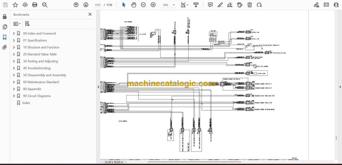
- 90 Circuit Diagrams
- Table of Contents
- Abbreviation List
- Hydraulic Circuit Diagram
- Symbols Used in Hydraulic Circuit Diagram
- Hydraulic Circuit Diagram: PC30MR-5,PC30MR5-E1
- Hydraulic Circuit Diagram (Quick Coupler Specifications): PC30MR-5 (1/2)
- Hydraulic Circuit Diagram (Quick Coupler Specifications): PC30MR-5 (2/2)
- Hydraulic Circuit Diagram: PC35MR-5,PC35MR5-E1
- Hydraulic Circuit Diagram (Quick Coupler Specifications): PC35MR-5 (1/2)
- Hydraulic Circuit Diagram (Quick Coupler Specifications): PC35MR-5 (2/2)
- Electrical Circuit Diagram
- Symbols Used in Electric Circuit Diagram
- Electrical Circuit Diagram (Canopy Spec) (Serial Number: 50001 – 52907)(1/5)
- Electrical Circuit Diagram (Canopy Spec) (Serial Number: 50001 – 52907)(2/5)
- Electrical Circuit Diagram (Canopy Spec) (Serial Number: 50001 – 52907)(3/5)
- Electrical Circuit Diagram (Canopy Spec) (Serial Number: 50001 – 52907)(4/5)
- Electrical Circuit Diagram (Canopy Spec) (Serial Number: 50001 – 52907)(5/5)
- Electrical Circuit Diagram (Canopy Spec) (Serial Number: 52908 – 64000)(1/5)
- Electrical Circuit Diagram (Canopy Spec) (Serial Number: 52908 – 64000)(2/5)
- Electrical Circuit Diagram (Canopy Spec) (Serial Number: 52908 – 64000)(3/5)
- Electrical Circuit Diagram (Canopy Spec) (Serial Number: 52908 – 64000)(4/5)
- Electrical Circuit Diagram (Canopy Spec) (Serial Number: 52908 – 64000)(5/5)
- Electrical Circuit Diagram (Canopy Spec)(PC30MR-5 Serial Number: 64001 and up, PC30MR-5E1 Serial Number: 1001 and up)(1/5)
- Electrical Circuit Diagram (Canopy Spec)(PC30MR-5 Serial Number: 64001 and up, PC30MR-5E1 Serial Number: 1001 and up)(2/5)
- Electrical Circuit Diagram (Canopy Spec)(PC30MR-5 Serial Number: 64001 and up, PC30MR-5E1 Serial Number: 1001 and up)(3/5)
- Electrical Circuit Diagram (Canopy Spec)(PC30MR-5 Serial Number: 64001 and up, PC30MR-5E1 Serial Number: 1001 and up)(4/5)
- Electrical Circuit Diagram (Canopy Spec)(PC30MR-5 Serial Number: 64001 and up, PC30MR-5E1 Serial Number: 1001 and up)(5/5)
- Electrical Circuit Diagram (Canopy Spec) (Serial Number: 30001 – 31037)(1/5)
- Electrical Circuit Diagram (Canopy Spec) (Serial Number: 30001 – 31037)(2/5)
- Electrical Circuit Diagram (Canopy Spec) (Serial Number: 30001 – 31037)(3/5)
- Electrical Circuit Diagram (Canopy Spec) (Serial Number: 30001 – 31037)(4/5)
- Electrical Circuit Diagram (Canopy Spec) (Serial Number: 30001 – 31037)(5/5)
- Electrical Circuit Diagram (Canopy Spec) (Serial Number: 31038 – 35000)(1/5)
- Electrical Circuit Diagram (Canopy Spec) (Serial Number: 31038 – 35000)(2/5)
- Electrical Circuit Diagram (Canopy Spec) (Serial Number: 31038 – 35000)(3/5)
- Electrical Circuit Diagram (Canopy Spec) (Serial Number: 31038 – 35000)(4/5)
- Electrical Circuit Diagram (Canopy Spec) (Serial Number: 31038 – 35000)(5/5)
- Electrical Circuit Diagram (Canopy Spec)(PC35MR-5 Serial Number: 35001 and up, PC35MR-5E1 Serial Number: 2001 and up)(1/5)
- Electrical Circuit Diagram (Canopy Spec)(PC35MR-5 Serial Number: 35001 and up, PC35MR-5E1 Serial Number: 2001 and up)(2/5)
- Electrical Circuit Diagram (Canopy Spec)(PC35MR-5 Serial Number: 35001 and up, PC35MR-5E1 Serial Number: 2001 and up)(3/5)
- Electrical Circuit Diagram (Canopy Spec)(PC35MR-5 Serial Number: 35001 and up, PC35MR-5E1 Serial Number: 2001 and up)(4/5)
- Electrical Circuit Diagram (Canopy Spec)(PC35MR-5 Serial Number: 35001 and up, PC35MR-5E1 Serial Number: 2001 and up)(5/5)
- Electrical Circuit Diagram (For Canopy Spec Machine with Quick Coupler) (Serial Number: 50001 – 52556)(1/5)
- Electrical Circuit Diagram (For Canopy Spec Machine with Quick Coupler) (Serial Number: 50001 – 52556)(2/5)
- Electrical Circuit Diagram (For Canopy Spec Machine with Quick Coupler) (Serial Number: 50001 – 52556)(3/5)
- Electrical Circuit Diagram (For Canopy Spec Machine with Quick Coupler) (Serial Number: 50001 – 52556)(4/5)
- Electrical Circuit Diagram (For Canopy Spec Machine with Quick Coupler) (Serial Number: 50001 – 52556)(5/5)
- Electrical Circuit Diagram (For Canopy Spec Machine with Quick Coupler) (Serial Number: 52557 – 64000)(1/5)
- Electrical Circuit Diagram (For Canopy Spec Machine with Quick Coupler) (Serial Number: 52557 – 64000)(2/5)
- Electrical Circuit Diagram (For Canopy Spec Machine with Quick Coupler) (Serial Number: 52557 – 64000)(3/5)
- Electrical Circuit Diagram (For Canopy Spec Machine with Quick Coupler) (Serial Number: 52557 – 64000)(4/5)
- Electrical Circuit Diagram (For Canopy Spec Machine with Quick Coupler) (Serial Number: 52557 – 64000)(5/5)
- Electrical Circuit Diagram (For Canopy Spec Machine with Quick Coupler) (Serial Number: 64001 and up)(1/5)
- Electrical Circuit Diagram (For Canopy Spec Machine with Quick Coupler) (Serial Number: 64001 and up)(2/5)
- Electrical Circuit Diagram (For Canopy Spec Machine with Quick Coupler) (Serial Number: 64001 and up)(3/5)
- Electrical Circuit Diagram (For Canopy Spec Machine with Quick Coupler) (Serial Number: 64001 and up)(4/5)
- Electrical Circuit Diagram (For Canopy Spec Machine with Quick Coupler) (Serial Number: 64001 and up)(5/5)
- Electrical Circuit Diagram (For Canopy Spec Machine with Quick Coupler) (Serial Number: 30001 – 30888)(1/5)
- Electrical Circuit Diagram (For Canopy Spec Machine with Quick Coupler) (Serial Number: 30001 – 30888)(2/5)
- Electrical Circuit Diagram (For Canopy Spec Machine with Quick Coupler) (Serial Number: 30001 – 30888)(3/5)
- Electrical Circuit Diagram (For Canopy Spec Machine with Quick Coupler) (Serial Number: 30001 – 30888)(4/5)
- Electrical Circuit Diagram (For Canopy Spec Machine with Quick Coupler) (Serial Number: 30001 – 30888)(5/5)
- Electrical Circuit Diagram (For Canopy Spec Machine with Quick Coupler) (Serial Number: 30889 – 35000)(1/5)
- Electrical Circuit Diagram (For Canopy Spec Machine with Quick Coupler) (Serial Number: 30889 – 35000)(2/5)
- Electrical Circuit Diagram (For Canopy Spec Machine with Quick Coupler) (Serial Number: 30889 – 35000)(3/5)
- Electrical Circuit Diagram (For Canopy Spec Machine with Quick Coupler) (Serial Number: 30889 – 35000)(4/5)
- Electrical Circuit Diagram (For Canopy Spec Machine with Quick Coupler) (Serial Number: 30889 – 35000)(5/5)
- Electrical Circuit Diagram (For Canopy Spec Machine with Quick Coupler) (Serial Number: 35001 and up)(1/5)
- Electrical Circuit Diagram (For Canopy Spec Machine with Quick Coupler) (Serial Number: 35001 and up)(2/5)
- Electrical Circuit Diagram (For Canopy Spec Machine with Quick Coupler) (Serial Number: 35001 and up)(3/5)
- Electrical Circuit Diagram (For Canopy Spec Machine with Quick Coupler) (Serial Number: 35001 and up)(4/5)
- Electrical Circuit Diagram (For Canopy Spec Machine with Quick Coupler) (Serial Number: 35001 and up)(5/5)
- Electrical Circuit Diagram (Cab Spec) (Serial Number: 50001 – 52848)(1/6)
- Electrical Circuit Diagram (Cab Spec) (Serial Number: 50001 – 52848)(2/6)
- Electrical Circuit Diagram (Cab Spec) (Serial Number: 50001 – 52848)(3/6)
- Electrical Circuit Diagram (Cab Spec) (Serial Number: 50001 – 52848)(4/6)
- Electrical Circuit Diagram (Cab Spec) (Serial Number: 50001 – 52848)(5/6)
- Electrical Circuit Diagram (Cab Spec) (Serial Number: 50001 – 52848)(6/6)
- Electrical Circuit Diagram (Cab Spec) (Serial Number: 52849 – 64000)(1/6)
- Electrical Circuit Diagram (Cab Spec) (Serial Number: 52849 – 64000)(2/6)
- Electrical Circuit Diagram (Cab Spec) (Serial Number: 52849 – 64000)(3/6)
- Electrical Circuit Diagram (Cab Spec) (Serial Number: 52849 – 64000)(4/6)
- Electrical Circuit Diagram (Cab Spec) (Serial Number: 52849 – 64000)(5/6)
- Electrical Circuit Diagram (Cab Spec) (Serial Number: 52849 – 64000)(6/6)
- Electrical Circuit Diagram (Cab Spec)(PC30MR-5 Serial Number: 64001 and up, PC30MR-5E1 Serial Number: 1001 and up)(1/6)
- Electrical Circuit Diagram (Cab Spec)(PC30MR-5 Serial Number: 64001 and up, PC30MR-5E1 Serial Number: 1001 and up)(2/6)
- Electrical Circuit Diagram (Cab Spec)(PC30MR-5 Serial Number: 64001 and up, PC30MR-5E1 Serial Number: 1001 and up)(3/6)
- Electrical Circuit Diagram (Cab Spec)(PC30MR-5 Serial Number: 64001 and up, PC30MR-5E1 Serial Number: 1001 and up)(4/6)
- Electrical Circuit Diagram (Cab Spec)(PC30MR-5 Serial Number: 64001 and up, PC30MR-5E1 Serial Number: 1001 and up)(5/6)
- Electrical Circuit Diagram (Cab Spec)(PC30MR-5 Serial Number: 64001 and up, PC30MR-5E1 Serial Number: 1001 and up)(6/6)
- Electrical Circuit Diagram (Cab Spec) (Serial Number: 30001 – 31023)(1/6)
- Electrical Circuit Diagram (Cab Spec) (Serial Number: 30001 – 31023)(2/6)
- Electrical Circuit Diagram (Cab Spec) (Serial Number: 30001 – 31023)(3/6)
- Electrical Circuit Diagram (Cab Spec) (Serial Number: 30001 – 31023)(4/6)
- Electrical Circuit Diagram (Cab Spec) (Serial Number: 30001 – 31023)(5/6)
- Electrical Circuit Diagram (Cab Spec) (Serial Number: 30001 – 31023)(6/6)
- Electrical Circuit Diagram (Cab Spec) (Serial Number: 31024 – 35000)(1/6)
- Electrical Circuit Diagram (Cab Spec) (Serial Number: 31024 – 35000)(2/6)
- Electrical Circuit Diagram (Cab Spec) (Serial Number: 31024 – 35000)(3/6)
- Electrical Circuit Diagram (Cab Spec) (Serial Number: 31024 – 35000)(4/6)
- Electrical Circuit Diagram (Cab Spec) (Serial Number: 31024 – 35000)(5/6)
- Electrical Circuit Diagram (Cab Spec) (Serial Number: 31024 – 35000)(6/6)
- Electrical Circuit Diagram (Cab Spec)(PC35MR-5 Serial Number: 35001 and up, PC35MR-5E1 Serial Number: 2001 and up)(1/6)
- Electrical Circuit Diagram (Cab Spec)(PC35MR-5 Serial Number: 35001 and up, PC35MR-5E1 Serial Number: 2001 and up)(2/6)
- Electrical Circuit Diagram (Cab Spec)(PC35MR-5 Serial Number: 35001 and up, PC35MR-5E1 Serial Number: 2001 and up)(3/6)
- Electrical Circuit Diagram (Cab Spec)(PC35MR-5 Serial Number: 35001 and up, PC35MR-5E1 Serial Number: 2001 and up)(4/6)
- Electrical Circuit Diagram (Cab Spec)(PC35MR-5 Serial Number: 35001 and up, PC35MR-5E1 Serial Number: 2001 and up)(5/6)
- Electrical Circuit Diagram (Cab Spec)(PC35MR-5 Serial Number: 35001 and up, PC35MR-5E1 Serial Number: 2001 and up)(6/6)
- Electrical Circuit Diagram (For Cab Spec Machine with Quick Coupler) (Serial Number: 50001 – 52556)(1/6)
- Electrical Circuit Diagram (For Cab Spec Machine with Quick Coupler) (Serial Number: 50001 – 52556)(2/6)
- Electrical Circuit Diagram (For Cab Spec Machine with Quick Coupler) (Serial Number: 50001 – 52556)(3/6)
- Electrical Circuit Diagram (For Cab Spec Machine with Quick Coupler) (Serial Number: 50001 – 52556)(4/6)
- Electrical Circuit Diagram (For Cab Spec Machine with Quick Coupler) (Serial Number: 50001 – 52556)(5/6)
- Electrical Circuit Diagram (For Cab Spec Machine with Quick Coupler) (Serial Number: 50001 – 52556)(6/6)
- Electrical Circuit Diagram (For Cab Spec Machine with Quick Coupler) (Serial Number: 52557 – 64000)(1/6)
- Electrical Circuit Diagram (For Cab Spec Machine with Quick Coupler) (Serial Number: 52557 – 64000)(2/6)
- Electrical Circuit Diagram (For Cab Spec Machine with Quick Coupler) (Serial Number: 52557 – 64000)(3/6)
- Electrical Circuit Diagram (For Cab Spec Machine with Quick Coupler) (Serial Number: 52557 – 64000)(4/6)
- Electrical Circuit Diagram (For Cab Spec Machine with Quick Coupler) (Serial Number: 52557 – 64000)(5/6)
- Electrical Circuit Diagram (For Cab Spec Machine with Quick Coupler) (Serial Number: 52557 – 64000)(6/6)
- Electrical Circuit Diagram (For Cab Spec Machine with Quick Coupler) (Serial Number: 64001 and up)(1/6)
- Electrical Circuit Diagram (For Cab Spec Machine with Quick Coupler) (Serial Number: 64001 and up)(2/6)
- Electrical Circuit Diagram (For Cab Spec Machine with Quick Coupler) (Serial Number: 64001 and up)(3/6)
- Electrical Circuit Diagram (For Cab Spec Machine with Quick Coupler) (Serial Number: 64001 and up)(4/6)
- Electrical Circuit Diagram (For Cab Spec Machine with Quick Coupler) (Serial Number: 64001 and up)(5/6)
- Electrical Circuit Diagram (For Cab Spec Machine with Quick Coupler) (Serial Number: 64001 and up)(6/6)
- Electrical Circuit Diagram (For Cab Spec Machine with Quick Coupler) (Serial Number: 30001 – 30888)(1/6)
- Electrical Circuit Diagram (For Cab Spec Machine with Quick Coupler) (Serial Number: 30001 – 30888)(2/6)
- Electrical Circuit Diagram (For Cab Spec Machine with Quick Coupler) (Serial Number: 30001 – 30888)(3/6)
- Electrical Circuit Diagram (For Cab Spec Machine with Quick Coupler) (Serial Number: 30001 – 30888)(4/6)
- Electrical Circuit Diagram (For Cab Spec Machine with Quick Coupler) (Serial Number: 30001 – 30888)(5/6)
- Electrical Circuit Diagram (For Cab Spec Machine with Quick Coupler) (Serial Number: 30001 – 30888)(6/6)
- Electrical Circuit Diagram (For Cab Spec Machine with Quick Coupler) (Serial Number: 30889 – 35000)(1/6)
- Electrical Circuit Diagram (For Cab Spec Machine with Quick Coupler) (Serial Number: 30889 – 35000)(2/6)
- Electrical Circuit Diagram (For Cab Spec Machine with Quick Coupler) (Serial Number: 30889 – 35000)(3/6)
- Electrical Circuit Diagram (For Cab Spec Machine with Quick Coupler) (Serial Number: 30889 – 35000)(4/6)
- Electrical Circuit Diagram (For Cab Spec Machine with Quick Coupler) (Serial Number: 30889 – 35000)(5/6)
- Electrical Circuit Diagram (For Cab Spec Machine with Quick Coupler) (Serial Number: 30889 – 35000)(6/6)
- Electrical Circuit Diagram (For Cab Spec Machine with Quick Coupler) (Serial Number: 35001 and up)(1/6)
- Electrical Circuit Diagram (For Cab Spec Machine with Quick Coupler) (Serial Number: 35001 and up)(2/6)
- Electrical Circuit Diagram (For Cab Spec Machine with Quick Coupler) (Serial Number: 35001 and up)(3/6)
- Electrical Circuit Diagram (For Cab Spec Machine with Quick Coupler) (Serial Number: 35001 and up)(4/6)
- Electrical Circuit Diagram (For Cab Spec Machine with Quick Coupler) (Serial Number: 35001 and up)(5/6)
- Electrical Circuit Diagram (For Cab Spec Machine with Quick Coupler) (Serial Number: 35001 and up)(6/6)
- Index
Komatsu


