Format: PDF (Printable Document)
File Language: English
File Pages: 838
File Size: 25.65 MB (Speed Download Link)
Brand: Komatsu
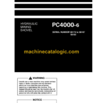
Model: PC4000-6 Hydraulic Mining Shovel
Book No: SM 08175-upD-GB-1
Serial No: 08175 to 08197 58102
Type of Document: Diagrams and Drawings Manual
$ 39
I.I Contents of the Binder
I.II Foreword
I.III Explanation of Abbrevations
SAFETY
CONTENTS
Overview
GENERAL PRECAUTIONS COMMON TO OPERATION ON THE EXCAVATOR
PRECAUTION FOR MAINTENANCE
ADDITIONAL SAFETY INFORMATION FOR TROUBLESHOOTING AND ADJUSTMENTS
SPECIAL SAFETY EQUIPMENT
1 MAIN ASSEMBLY GROUPS
1.1 General Layout
1.2 Superstructure
1.3 Machine House
1.4 Hydraulic Oil Reservoir
1.5 Hydraulic Oil Cooler
1.6 Fuel Tank
1.7 Counterweight
1.8 Cab Support
1.9 Operator’s Cab
1.10 Control Blocks
1.11 Swing Gears
1.12 Undercarriage
1.13 Backhoe Attachment (BHA)
1.14 Front Shovel Attachment (FSA)
III. SPECIFICATIONS
III.I Lifting Gears
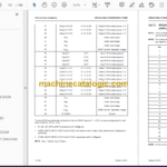
III.II Standard Tightening Torque Chart
III.III Conversion Table
III.IV General Specifications
2. DRIVE
2.1 Prime Drive Assembly
2.2 Engine and PTO Mounts
2.3 Fan Drive and Radiator Assembly
2.4 Pump Distributor Gearbox (PTO)
2.5 Geislinger Coupling
2.6 Air Filter
3. HYDRAULIC OIL RESERVOIR
3.1 General Layout
3.2 Main Oil Tank, Location of Electric Equipment.
3.3 Suction Oil Reservoir with Strainers
3.4 Return Oil Collector Tube with Strainer
3.5 Back Pressure Valve
3.6 Transfer Pump
3.7 Return and Leak Oil Filter
3.8 Breather Filter
4. HYDRAULIC OIL COOLING
4.1 General
4.2 Function of the Hydraulic Oil Cooling Circuit
4.3 Adjustment of the Back Pressure Valve
4.4 Fan Drive (Two Stage Cooler Fan RPM Control)
4.5 Adjustment of the Cooler Fan Drive Speed
5. CONTROLLING
5.1 General Layout
5.2 Control and Filter Panel Location of Components
5.3 Pilot Pressure Supply and Adjustments
5.4 Function Electro Hydraulic Control SYSTEM
5.5 Potentiometer Control (Lever, Joy Stick)
5.6 Potentiometer Control (Pedal)
5.7 Proportional Amplifier Module, Type A
5.8 Proportional Amplifier Module, Type B
5.9 Ramp Time Module
5.10 Adjustments of Amplifier Modules
5.11 Adjusting the Ramp Time Module
6. COMPONENTS
6.1 Main Control Blocks and High Pressure Filter (FSA)
6.2 Main Control Blocks and High Pressure Filter (BHA)
6.3 Distributor Manifold – Location of Restrictor Blocks and Anti Cavitation Valves (FSA)
6.4 Distributor Manifold – Location of Restrictor Blocks and Anti Cavitation Valves (BHA)
6.5 Single Control Blocks (Floating) for Stick and Boom (FSA)
6.6 Restrictor Block with Pressure Relief Valve
6.7 Anti cavitation valve block
6.8 Remote Control Valves
6.9 Directional Solenoid Valves (Three Positions / 4-Ways)
6.10 Proportional Solenoid Valve
6.11 High Pressure Filter
6.12 Control Blocks and Valves
6.13 Travel Brake Valve
6.14 Pressure Reducing Valve
6.15 Directional Solenoid Valves (Two Positions / 4-Ways)
6.16 Pressure Increasing Valve
6.17 Hydraulic Cylinder
6.18 Swing Ring
7. MAIN HYDRAULIC PUMPS AND PUMP REGULATION
7.1 General
7.2 Main Pumps
7.3 Electronic Pump Regulation System
7.4 Hydraulic Constant Regulation System
7.5 Determination of the Peak Point (Engine Performance)
7.6 Engine Speed Sensor (Pick up)
7.7 Energy Efficiency
8. OPERATING HYDRAULIC
8.1 General
8.2 Hydraulic for the Attachment Cylinder FSA and BHA
8.3 Hydraulic for the Swing Circuit
8.4 Hydraulic for the Travel Circuit
9. HYDRAULIC TRACK TENSIONING SYSTEM
9.1 General
9.2 Pressure Increasing Valve
9.3 Tensioning Cylinder
9.4 Adjustments / Checks
9.5 Functional Test
10. ACCESS LADDER HYDRAULICALLY OPERATED
10.1 General
10.2 Function of Hydraulically Operated Access Ladder
10.3 Adjustments / Checks
11. CENTRAL REFILLING SYSTEM (Service ARM)
11.1 General
11.2 Function
12. HINTS FOR READING THE HYDRAULIC DIAGRAM
12.1 General
12.2 Symbolic
13. HINTS FOR READING THE ELECTRIC CIRCUIT DIAGRAM
13.1 Designation of electrical components
13.2 Electric symbols
13.3 Symbols
13.4 Drawing Concept
13.5 Reading a Circuit Diagram
13.6 Component List
14 VEHICLE HEALTH MONITORING SYSTEM
14.1 General
14.2 Specifications for Operators
14.3 Specifications for Service
14.4 Wiring of the Main Components
14.5 General Design of THE PLC
14.6 How to proceed the Maintenance and Installation
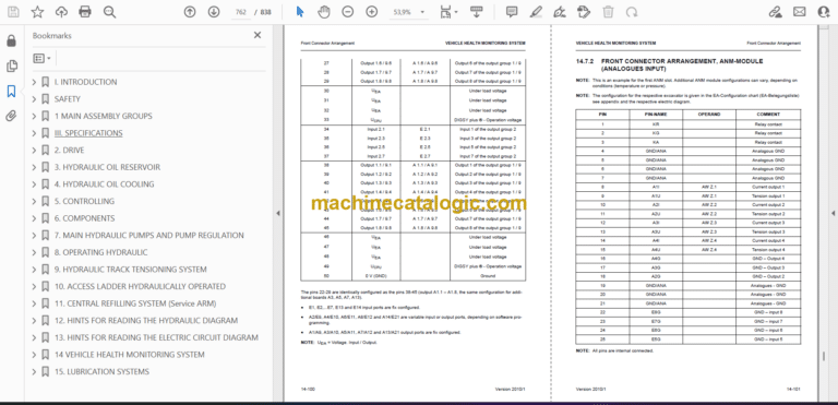
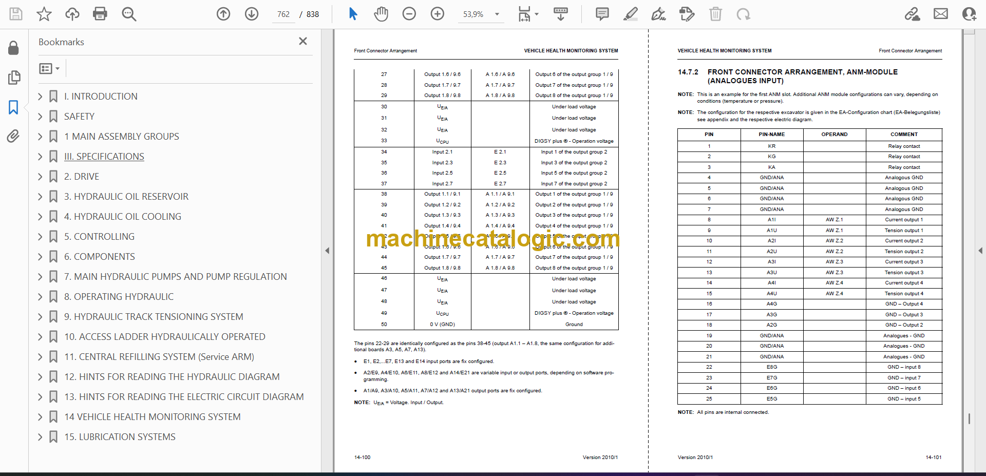
14.7 Front Connector Arrangement
14.8 Power Supply
14.9 Function Explanations with Electrical Diagram
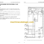
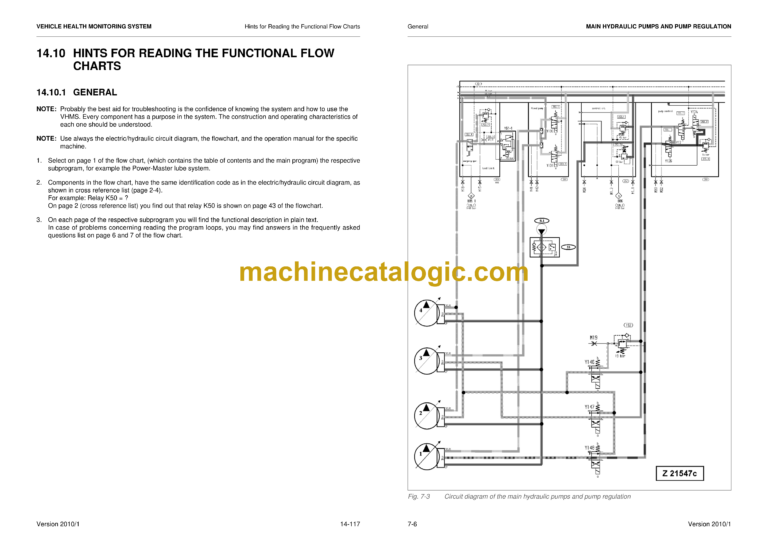
14.10 Hints for Reading the Functional Flow Charts
15. LUBRICATION SYSTEMS
15.1 Introduction
15.2 Central Lubrication System (CLS)
15.3 Lubrication Pump Station (SLS)
15.4 Operating and Controlling
15.5 Adjustments
15.6 Troubleshooting
15.7 Commissionin
