Format: PDF (Printable Document)
File Language: English
File Pages: 155
File Size: 15.81 MB (Speed Download Link)
Brand: Komatsu
Model: PC490LC-11PC490LC-11E0 Hydraulic Excavator
Book No: GEN00262-01
Serial No: 85001, 86088 and up
Type of Document: Field Assembly Manual
$ 39
Contents
FOREWORD
Foreword
WARNINGS
Safety Alert Symbol and Signal Words
SAFETY RULES, TOOLS AND EQUIPMENT
Safety Rules
Tools and Equipment for Assembly
Assembly Schedule
TRUCK COMPONENTS AND SPECIFICATIONS
Truck Components
Specifications
MAJOR COMPONENT WEIGHTS
Major Component Weights
FIELD WELDING FOR ASSEMBLY OR REPAIR
Introduction
General Repair Procedures
RECEIVING AND ASSEMBLY PREPARATION
Parts Preparation
CHASSIS ASSEMBLY
Assembly Introduction
Chassis Assembly
DUMP BODY ASSEMBLY
Dump Body General Information
FINAL ASSEMBLY
Final Assembly General Information
FINAL CHECKOUT
Perform Final Checkout
APPENDIX
Appendix
Torque Specifications
Suspension Oiling and Charging Procedures (58E-60-02200_04)
Suspension Oiling and Charging Block Kit Installation Procedure (FAM1208)
Oil and Nitrogen Specifications Chart (FAM1204)
Engine Emissions After-Treatment System (FAM0251)
Toe-In Adjustment (FAM1307)
Seat Belts and Tethers Checkout Procedure (SM2700_03)
Electric Checkout Procedure (58E-06-30910_00)
Interface Module Checkout Procedure (58E-06-21160_01)
Additional Electrical Checkout for Trucks with IM Controls (EM7279_01)
Hydraulic System Checkout Procedure (58E-60-10201_02)
Brake System Checkout Procedure (58E-60-10500_03)
Pre-Shift Brake Test Checkout Procedure (EM9966-5)
Payload Meter IV Checkout Procedure (58B-06-02400_06)
Komtrax Plus Setup Procedure (EM2128-1)
Komtrax Plus Checkout Procedure (EM2129-3)
Alternator Lock Assembly Checkout Procedure (58E-01-00540-01)
KomVision® Checkout Procedure (58E-43-10000_03)
Komatsu Wireless Bridge Checkout Procedure (58F-06-11130)
Reserve Oil System Checkout Procedure (58F-90-00400_01)
Auto Lube System (58F-90-00300_03)
Automatic Lubrication System (FAM1405)
Air Conditioning System Checkout Procedure (EM4003_02)
Field Assy Inspection Report (CEAW003219)
50 HOUR POST-COMMISSIONING CHECKSHEET (CEAW004210)
—————————————-
CONTENTS
SPECIFICATIONS
PRECAUTIONS FOR FIELD ASSEMBLY
ASSEMBLY PROCEDURE, NECESSARY EQUIPMENT, AND SCHEDULE
LAYOUT OF KIT
STYLE FOR TRANSPORTATION
LIST OF TOOLS FOR FIELD ASSEMBLING
TIGHTENING TORQUE
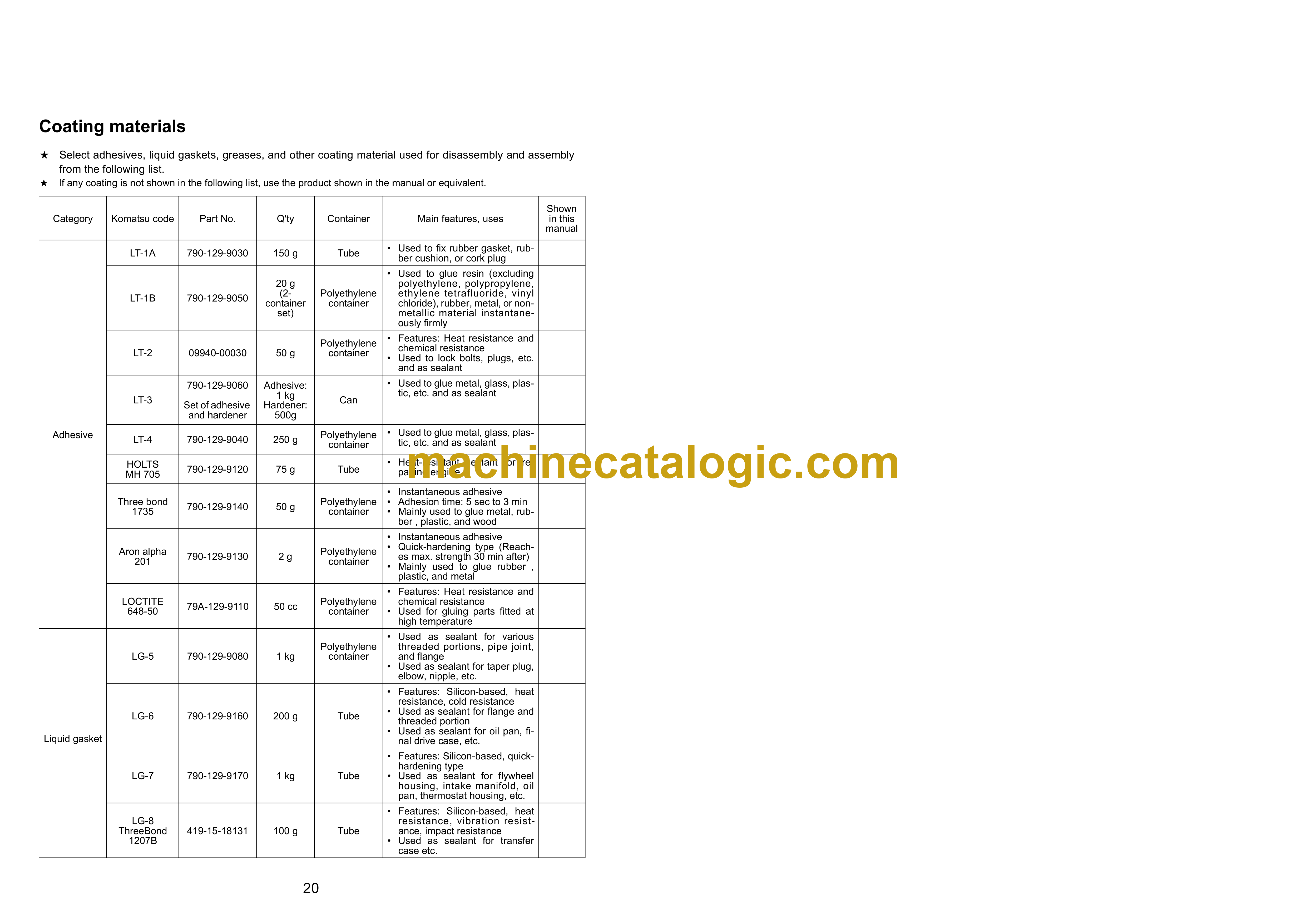
COATING MATERIALS LIST
Selection of wire ropes used for assembly
A. Assembly
A-1 Unloading and installing tractor
A-2 Installing track shoes
A-3 Installation of blade lift cylinder (1/2)
A-3 Installation of blade lift cylinder (2/2)
A-4 Assembly of blade (1/6)
A-4 Assembly of blade (2/6)
A-4 Assembly of blade (3/6)
A-4 Assembly of blade (4/6)
A-4 Assembly of blade (5/6)
A-4 Assembly of blade (6/6)
A-5 Installation of full roller guard (1/4)
A-5 Installation of full roller guard (2/4)
A-5 Installation of full roller guard (3/4)
A-5 Installation of full roller guard (4/4)
A-6 Installation of blade (1/3)
A-6 Installation of blade (2/3)
A-6 Installation of blade (3/3)
A-7 Installation of ripper assembly (1/12)
A-7 Installation of ripper assembly (2/12)
A-7 Installation of ripper assembly (3/12)
A-7 Installation of ripper assembly (4/12)
A-7 Installation of ripper assembly (5/12)
A-7 Installation of ripper assembly (6/12)
A-7 Installation of ripper assembly (7/12)
A-7 Installation of ripper assembly (8/12)
A-7 Installation of ripper assembly (9/12)
A-7 Installation of ripper assembly (10/12)
A-7 Installation of ripper assembly (11/12)
A-7 Installation of ripper assembly (12/12)
A-8 Installation of operator’s cab (1/17)
A-8 Installation of operator’s cab (2/17)
A-8 Installation of operator’s cab (3/17)
A-8 Installation of operator’s cab (4/17)
A-8 Installation of operator’s cab (5/17)
A-8 Installation of operator’s cab (6/17)
A-8 Installation of operator’s cab (7/17)
A-8 Installation of operator’s cab (8/17)
A-8 Installation of operator’s cab (9/17)
A-8 Installation of operator’s cab (10/17)
A-8 Installation of operator’s cab (11/17)
A-8 Installation of operator’s cab (12/17)
A-8 Installation of operator’s cab (13/17)
A-8 Installation of operator’s cab (14/17)
A-8 Installation of operator’s cab (15/17)
A-8 Installation of operator’s cab (16/17)
A-8 Installation of operator’s cab (17/17)
A-9 Check track tension (1/2)
A-9 Check track tension (2/2)
A-10 Check of oil and coolant levels (1/2)
A-10 Check of oil and coolant levels (2/2)
A-11 Lubricating (1/3)
A-11 Lubricating (2/3)
A-11 Lubricating (3/3)
A-12 Bleeding air from hydraulic cylinders (1/2)
A-12 Bleeding air from hydraulic cylinders (2/2)
A-13 Installation of additional working lamps (1/3)
A-13 Installation of additional working lamps (2/3)
A-13 Installation of additional working lamps (3/3)
A-14 Installation of revolving warning lamp
A-15 Installation of KOMTRAX parts (1/6)
A-15 Installation of KOMTRAX parts (2/6)
A-15 Installation of KOMTRAX parts (3/6)
A-15 Installation of KOMTRAX parts (4/6)
A-15 Installation of KOMTRAX parts (5/6)
A-15 Installation of KOMTRAX parts (6/6)
A-16 Installation of KOMTRAX antenna
A-17 Installation of fire extinguisher (1/2)
A-17 Installation of fire extinguisher (2/2)
A-18 Installation of exhaust pipe
M. CHECK AND MAINTENANCE PROCEDURES AFTER COMPLETION OF ASSEMBLY
M-1 Testing and adjusting operator’s cab (1/10)
M-1 Testing and adjusting operator’s cab (2/10)
M-1 Testing and adjusting operator’s cab (3/10)
M-1 Testing and adjusting operator’s cab (4/10)
M-1 Testing and adjusting operator’s cab (5/10)
M-1 Testing and adjusting operator’s cab (6/10)
M-1 Testing and adjusting operator’s cab (7/10)
M-1 Testing and adjusting operator’s cab (8/10)
M-1 Testing and adjusting operator’s cab (9/10)
M-1 Testing and adjusting operator’s cab (10/10)
M-2 Replacement of return filter (Standard filter to flushing filter) (1/2)
M-2 Replacement of return filter (Standard filter to flushing filter) (2/2)
M-3 Flushing of hydraulic circuit, and bleeding air from hydraulic cylinders (Part 1)
M-4 Replacement of return filter (Flushing filter to standard filter) (1/2)
M-4 Replacement of return filter (Flushing filter to standard filter) (2/2)
M-5 Bleeding air from hydraulic cylinders (Part 2)
FIELD ASSEMBLY INSPECTION REPORT


