These Komatsu PC600-8 and PC600LC-8 crawler excavators are big production machines, usually on quarry faces, heavy demo, or serious earthmoving. The Komatsu PC600-8, PC600LC-8 Crawler Excavator Shop Manual (SEN00128-27) is what shop guys and field techs reach for when something’s broken, out of spec, or coming apart on the bench. People buy this when they’re past “daily checks” and need proper teardown and troubleshooting info, not just fluid intervals. If you’re trying to keep one of these earning instead of parked, this is the kind of book you lean on.
What this manual helps you do
- Trace hydraulic faults in the main and auxiliary circuits using step‑by‑step diagnostic flow and system layout information.
- Check engine, fuel, and cooling system issues with guided tests that point you toward likely failed components instead of random parts swapping.
- Follow disassembly and reassembly sequences for major components like final drives, swing machinery, cylinders, and travel motors.
- Diagnose electrical problems using wiring information, connector views, and logical fault-tracing procedures for sensors and controllers.
- Handle adjustments and calibrations on controls and linkages so the machine digs straight, swings correctly, and responds the way it should.
Who this is for
If you’re a field tech, shop mechanic, or fleet maintenance lead working on these exact Komatsu PC600-8 / PC600LC-8 units, this is the right level of book. If you’re an operator or owner just wanting basic maintenance intervals and button layouts, you’re really looking for the Operation & Maintenance manual instead.
FAQ
Q: Is this a PDF I can search and print?
A: Yes, this is a digital PDF, so you can search by keyword and print the pages you want to take to the machine.
Q: Is it detailed enough for full overhauls?
A: Shop manuals for this class of Komatsu excavator usually cover workshop-level repairs, including diagnostics, teardown sequences, and reassembly guidance.
Q: How do I know if it matches my exact machine variant?
A: You’ll want to match your model designation to PC600-8 or PC600LC-8 and confirm the book reference SEN00128-27 against your Komatsu documentation or dealer.
Bottom line: if you’re the one actually turning wrenches on a PC600-8 or PC600LC-8, this is the manual you buy; if you just run the machine or do light service, keep looking for the O&M book instead.
📘 Show Index
Table of Contents:
- 00 Index and foreword
- Index
- Composition of shop manual
- Table of contents
- Foreword and general information
- Safety notice
- How to read the shop manual
- Explanation of terms for maintenance standard
- Handling of electric equipment and hydraulic component
- Handling of connectors newly used for engines
- How to read electric wire code
- Precautions when carrying out operation
- Method of disassembling and connecting push-pull type coupler
- Standard tightening torque table
- Conversion table
- 01 Specification
- Specification and technical data
- Specification drawings
- Working range drawings
- Specifications
- Weight table
- Table of fuel, coolant and lubricants
- 10 Structure, function and maintenance standard
- Engine and cooling system
- Parts related to engine
- PTO
- Fan, control and PTO lubrication pump
- Radiator, oil cooler
- Power train
- Power train
- Final drive
- Sprocket
- Swing circle
- Swing machinery
- Undercarriage and frame
- Track frame, recoil spring
- Idler
- Carrier roller
- Track roller
- Track shoe
- Hydraulic system, Part 1
- Hydraulic system, Part 1
- Hydraulic piping drawing
- Hydraulic tank, hydraulic filter
- Hydraulic pump (piston pump)
- Line oil filter
- Cooling fan pump
- Cooling fan motor
- Hydraulic system, Part 2
- Control valve
- Swing motor
- Swing brake
- Safety valve
- Reverse prevention valve
- Center swivel joint
- Travel motor
- Parking brake
- Brake valve
- Set pressures varying mechanism
- Valve control
- Work equipment, swing PPC valve
- Travel PPC valve
- Service PPC valve
- PPC accumulator
- PPC shuttle valve
- Solenoid valve
- Boom holding valve
- Boom LOWER regeneration valve
- Quick return valve
- Hydraulic cylinder
- Work equipment
- Work equipment
- Dimensions of work equipment
- Cab and its attachments
- Electrical system
- Engine control
- Machine control system diagram
- Monitor system
- Sensors
- KOMTRAX system
- 20 Standard value table
- Standard service value table
- Standard value table for engine
- Standard value table for chassis
- 30 Testing and adjusting
- Testing and adjusting, Part 1
- Tools for testing, adjusting and troubleshooting
- Measuring engine speed
- Measuring intake air pressure (boost pressure)
- Measuring exhaust gas temperature
- Measuring exhaust gas color
- Adjusting valve clearance
- Measuring compression pressure
- Measuring blow-by pressure
- Measuring engine oil pressure
- Testing EGR valve and bypass valve drive oil pressure
- Handling equipment in fuel circuit
- Releasing remaining pressure in fuel system
- Measuring fuel pressure
- Reduced cylinder mode operation
- No-injection cranking
- Testing leakage from pressure limiter and return rate from injector
- Bleeding air from fuel circuit
- Testing fuel system for leakage
- Testing and adjusting alternator belt tension
- Testing and adjusting air conditioner compressor belt tension
- Testing clearance of swing circle bearing
- Testing and adjusting track shoe tension
- Testing and adjusting work equipment, swing, and travel circuit oil pressures
- Testing and adjusting control circuit oil pressure
- Testing and adjusting piston pump control oil pressure
- Testing servo piston stroke
- Measuring PPC valve output pressure
- Measuring outlet pressures of solenoid valve and PPC shuttle valve
- Adjusting work equipment, swing PPC valve
- Testing and adjusting travel deviation
- Measuring fan speed
- Measuring fan circuit oil pressure
- Inspection of locations of hydraulic drift of work equipment
- Measuring oil leakage
- Releasing remaining pressure in hydraulic circuit
- Bleeding air from each part
- Inspection procedures for diode
- Testing and adjusting, Part 2
- Special function of machine monitor
- Handling controller voltage circuit
- Procedure for turning on KOMTRAX terminal
- KOMTRAX terminal lamp indications
- Preparation work for troubleshooting electrical system
- Adjusting mirrors
- Pm-clinic service
- Undercarriage inspection
- 40 Troubleshooting
- Failure code table and fuse locations
- Failure codes table
- Fuse locations
- General information on troubleshooting
- Points to remember when troubleshooting
- Sequence of events in troubleshooting
- Checks before troubleshooting
- Classification and procedures of troubleshooting
- Information contained in troubleshooting table
- Failure-looking phenomenon and troubleshooting No.
- Connection table for connector pin numbers
- T- branch box and T- branch adapter table
- Troubleshooting by failure code (Display of code), Part 1
- Failure code [A000N1] Eng. Hi Out of Std
- Failure code [AA10NX] Aircleaner clogging
- Failure code [AB00KE] Charge Voltage Low
- Failure code [B@BAZG] Eng. Oil Press. Low
- Failure code [B@BAZK] Eng. Oil Level Low
- Failure code [B@BCNS] Eng. Water Overheat
- Failure code [B@BCZK] Eng. Water Lvl Low
- Failure code [B@HANS] Hydr. Oil Overheat
- Failure code [CA111] ECM Critical Internal Failure
- Failure code [CA115] Eng Ne and Bkup Speed Sens Error
- Failure code [CA122] Chg Air Press Sensor High Error
- Failure code [CA123] Chg Air Press Sensor Low Error
- Failure code [CA131] Throttle Sensor High Error
- Failure code [CA132] Throttle Sensor Low Error
- Failure code [CA135] Eng Oil Press Sensor High Error
- Failure code [CA141] Eng Oil Press Sensor Low Error
- Failure code [CA144] Coolant Temp Sens High Error
- Failure code [CA145] Coolant Temp Sens Low Error
- Failure code [CA153] Chg Air Temp Sensor High Error
- Failure code [CA154] Chg Air Temp Sensor Low Error
- Failure code [CA187] Sens Supply 2 Volt Low Error
- Failure code [CA221] Ambient Press Sens High Error
- Failure code [CA222] Ambient Press Sens Low Error
- Failure code [CA227] Sens Supply 2 Volt High Error
- Failure code [CA234] Eng Overspeed
- Failure code [CA238] Ne Speed Sens Supply Volt Error
- Failure code [CA263] Fuel Temp Sensor High Error
- Failure code [CA265] Fuel Temp Sensor Low Error
- Failure code [CA271] IMV/PCV1 Short Error
- Failure code [CA272] IMV/PCV1 Open Error
- Failure code [CA273] PCV2 Short Error
- Failure code [CA274] PCV2 Open Error
- Troubleshooting by failure code (Display of code), Part 2
- Failure code [CA322] Inj #1 (L#1) Open/Short Error
- Failure code [CA323] Inj #5 (L#5) Open/Short Error
- Failure code [CA324] Inj #3 (L#3) Open/Short Error
- Failure code [CA325] Inj #6 (L#6) Open/Short Error
- Failure code [CA331] Inj #2 (L#2) Open/Short Error
- Failure code [CA332] Inj #4 (L#4) Open/Short Error
- Failure code [CA342] Calibration Code Incompatibility
- Failure code [CA351] Injectors Drive Circuit Error
- Failure code [CA352] Sens Supply 1 Volt Low Error
- Failure code [CA386] Sens Supply 1 Volt High Error
- Failure code [CA441] Battery Voltage Low Error
- Failure code [CA442] Battery Voltage High Error
- Failure code [CA449] Rail Press Very High Error
- Failure code [CA451] Rail Press Sensor High Error
- Failure code [CA452] Rail Press Sensor Low Error
- Failure code [CA553] Rail Press High Error
- Failure code [CA554] Rail Press Sensor In Range Error
- Failure code [CA559] Rail Press Low Error
- Failure code [CA689] Eng Ne Speed Sensor Error
- Failure code [CA731] Eng Bkup Speed Sens Phase Error
- Failure code [CA757] All Persistent Data Lost Error
- Failure code [CA778] Engine Bkup Speed Sensor Error
- Failure code [CA1228] EGR Valve Servo Error 1
- Failure code [CA1625] EGR Valve Servo Error 2
- Failure code [CA1626] BP Valve Sol Current High Error
- Failure code [CA1627] BP Valve Sol Current Low Error
- Failure code [CA1628] Bypass Valve Servo Error 1
- Failure code [CA1629] Bypass Valve Servo Error 2
- Failure code [CA1631] BP Valve Pos Sens High Error
- Failure code [CA1632] BP Valve Pos Sens Low Error
- Failure code [CA1633] KOMNET Datalink Timeout Error
- Failure code [CA1642] EGR Inlet Press Sens Low Error
- Failure code [CA1653] EGR Inlet Press Sens High Error
- Failure code [CA2185] Throt Sens Sup Volt High Error
- Failure code [CA2186] Throt Sens Sup Volt Low Error
- Failure code [CA2249] Rail Press Very Low Error
- Failure code [CA2271] EGR Valve Pos Sens High Error
- Failure code [CA2272] EGR Valve Pos Sens Low Error
- Failure code [CA2351] EGR Valve Sol Current High Error
- Failure code [CA2352] EGR Valve Sol Current Low Error
- Failure code [CA2555] Grid Htr Relay Volt Low Error
- Failure code [CA2556] Grid Htr Relay Volt High Error
- Troubleshooting by failure code (Display of code), Part 3
- Failure code [D110KB] Battery Relay Drive S/C
- Failure code [D163KB] Flash Light Relay S/C
- Failure code [D195KB] Step Light Relay S/C
- Failure code [DA22KK] Pump Solenoid Power Low Error
- Failure code [DA25KP] Press. Sensor Power Abnormality
- Failure code [DA2SKQ] Model Selection Abnormality
- Failure code [DA80MA] Auto. Lub Abnormal
- Failure code [DA2RMC] Pump Comm. Abnormality
- Failure code [DAFRMC] Monitor Comm. Abnormality
- Failure code [DGE5KY] Ambi. Temp. Sensor S/C
- Failure code [DGH2KB] Hydr. Oil Temp. Sensor S/C
- Failure code [DHPAMA] F pump P. Sensor Abnormality
- Failure code [DHPBMA] R pump P. Sensor Abnormality
- Failure code [DV20KB] Travel Alarm S/C
- Failure code [DW43KA] Travel Speed Sol. Disc.
- Failure code [DW43KB] Travel Speed Sol. S/C
- Failure code [DW45KA] Swing Brake Sol. Disc.
- Failure code [DW45KB] Swing Brake Sol. S/C
- Failure code [DW48KA] CO Cancel Sol. Disc.
- Failure code [DW48KB] CO Cancel Sol. S/C
- Failure code [DW7BKA] Fan Reverse Sol. Disc.
- Failure code [DW7BKB] Fan Reverse Sol. S/C
- Failure code [DW4XKA] Bucket Curl Hi Cancel Sol. Disc.
- Failure code [DW4XKB] Bucket Curl Hi Cancel Sol. S/C
- Failure code [DWK0KA] 2-stage Relief Sol. Disc.
- Failure code [DWK0KB] 2-stage Relief Sol. S/C
- Failure code [DX16KA] Fan Pump EPC Sol. Disc.
- Failure code [DX16KB] Fan Pump EPC Sol. S/C
- Failure code [DXA0KA] TVC Sol. Disc.
- Failure code [DXA0KB] TVC Sol. S/C
- Failure code [DY20KA] Wiper Working Abnormality
- Failure code [DY20MA] Wiper Parking Abnormality
- Failure code [DY2CKB] Washer Drive S/C
- Failure code [DY2DKB] Wiper Drive (For) S/C
- Failure code [DY2EKB] Wiper Drive (Rev) S/C
- Troubleshooting of electrical system (E-mode)
- E-1 Engine does not start (Engine does not rotate)
- E-2 Preheater does not operate
- E-3 Auto engine warm-up device does not work
- E-4 Auto-decelerator does not operate
- E-5 All work equipment, swing and travel do not move
- E-6 Power max. function does not operate
- E-7 Machine push-up function does not operate normally
- E-8 Any item is not displayed on machine monitor
- E-9 Part of display on machine monitor is missing
- E-10 Machine monitor displays contents irrelevant to the model
- E-11 Fuel level monitor red lamp lights up while engine is running
- E-12 Engine coolant temperature gauge does not display correctly
- E-13 Hydraulic oil temperature gauge does not display correctly
- E-14 Fuel gauge does not display correctly
- E-15 Swing lock monitor does not display correctly
- E-16 When monitor switch is operated, nothing is displayed
- E-17 Wiper and window washer do not work
- E-18 "Boom Raise" is not correctly displayed in monitoring function
- E-19 "Boom Lower" is not correctly displayed in monitoring function
- E-20 "Arm IN" is not correctly displayed in monitoring function
- E-21 "Arm OUT" is not correctly displayed in monitoring function
- E-22 "Bucket CURL" is not correctly displayed in monitoring function
- E-23 "Bucket DUMP" is not correctly displayed in monitoring function
- E-24 "Swing" is not correctly displayed in monitoring function
- E-25 "Travel" is not correctly displayed in monitoring function
- E-26 Air conditioner does not work
- E-27 Step light does not light up or go off
- E-28 Electric grease gun does not operate
- E-29 Travel alarm does not sound or does not stop sounding
- E-30 Horn does not sound
- E-31 Bottom dump does not move
- Troubleshooting of hydraulic and mechanical system (H-mode)
- Before troubleshooting H-mode
- Information in troubleshooting table
- H-1 Speed or power of all work equipment, travel, and swing is low
- H-2 Engine speed lowers remarkably or engine stalls
- H-3 All work equipment, travel, and swing systems do not work
- H-4 Abnormal sound is heard from around pump
- H-5 Auto-decelerator is not reset
- H-6 Boom speed or power is low
- H-7 Arm speed or power is low
- H-8 Bucket speed or power is low
- H-9 Boom does not move
- H-10 Arm does not move
- H-11 Bucket does not move
- H-12 Bottom dump does not move
- H-13 Hydraulic drift of work equipment is large
- H-14 Time lag of work equipment is large
- H-15 Power max. function does not operate or stop
- H-16 Machine push-up function does not operate or stop
- H-17 When arm and boom, bucket are operated simultaneously, boom, bucket speed is low
- H-18 When bucket and boom, arm, swing, travel are operated simultaneously, boom, arm, swing, travel speed is low
- H-19 When arm and swing are operated simultaneously, swing speed is low
- H-20 Machine deviates in one direction
- H-21 Machine deviates largely at start
- H-22 Travel deviation is large during compound operation
- H-23 Travel speed or power is low
- H-24 Machine does not travel (only one track)
- H-25 Travel speed does not change
- H-26 Upper structure does not swing
- H-27 Swing speed or acceleration is low
- H-28 Upper structure overruns excessively when it stops swinging
- H-29 Large shock is made when upper structure stops swinging
- H-30 Large abnormal sound is made when upper structure stops swinging
- H-31 Hydraulic drift of swing is large
- Troubleshooting of engine (S-mode)
- Method of using troubleshooting chart
- S-1 Starting performance is poor
- S-2 Engine does not start
- S-3 Engine does not pick up smoothly
- S-4 Engine stops during operations
- S-5 Engine does not rotate smoothly
- S-6 Engine lacks output (or lacks power)
- S-7 Exhaust smoke is black (incomplete combustion)
- S-8 Oil consumption is excessive (or exhaust smoke is blue)
- S-9 Oil becomes contaminated quickly
- S-10 Fuel consumption is excessive
- S-11 Oil is in coolant (or coolant spurts back or coolant level goes down)
- S-12 Oil pressure drops
- S-13 Oil level rises (Entry of coolant or fuel)
- S-14 Coolant temperature becomes too high (overheating)
- S-15 Abnormal noise is made
- S-16 Vibration is excessive
- 50 Disassembly and assembly
- General information on disassembly and assembly
- How to read this manual
- Coating materials list
- Special tools list
- Sketches of special tools
- Engine and cooling system, Part 1
- Removal and installation of fuel supply pump assembly
- Removal and installation of cylinder head assembly
- Removal and installation of fuel injector assembly
- Removal and installation of engine front seal
- Removal and installation of engine rear seal
- Engine and cooling system, Part 2
- Removal and installation of engine, PTO and hydraulic pump assembly
- Removal and installation of radiator assembly
- Removal and installation of hydraulic oil cooler assembly
- Removal and installation of aftercooler assembly
- Removal and installation of fan motor assembly
- Removal and installation of fuel tank assembly
- Power train
- Removal and installation of PTO assembly
- Disassembly and assembly of PTO assembly
- Removal and installation of swing motor and swing machinery assembly
- Disassembly and assembly of swing machinery assembly
- Removal and installation of swing circle assembly
- Disassembly and assembly of final drive assembly
- Undercarriage and frame
- Removal and installation of track shoe assembly
- Disassembly and assembly of 1 link in field
- Removal and installation of idler, recoil spring assembly
- Disassembly and assembly of idler assembly
- Disassembly and assembly of recoil spring assembly
- Removal and installation of track roller assembly
- Disassembly and assembly of track roller assembly
- Removal and installation of carrier roller assembly
- Disassembly and assembly of carrier roller assembly
- Removal and installation of revolving frame assembly
- Removal and installation of counterweight assembly
- Removal and installation of counterweight remover assembly
- Hydraulic system
- Removal and installation of hydraulic tank assembly
- Removal and installation of hydraulic pump assembly
- Removal and installation of control valve and solenoid valve assembly
- Disassembly and assembly of control valve assembly
- Disassembly and assembly of main control valve assembly
- Removal and installation of swing motor assembly
- Removal and installation of center swivel joint assembly
- Disassembly and assembly of center swivel joint assembly
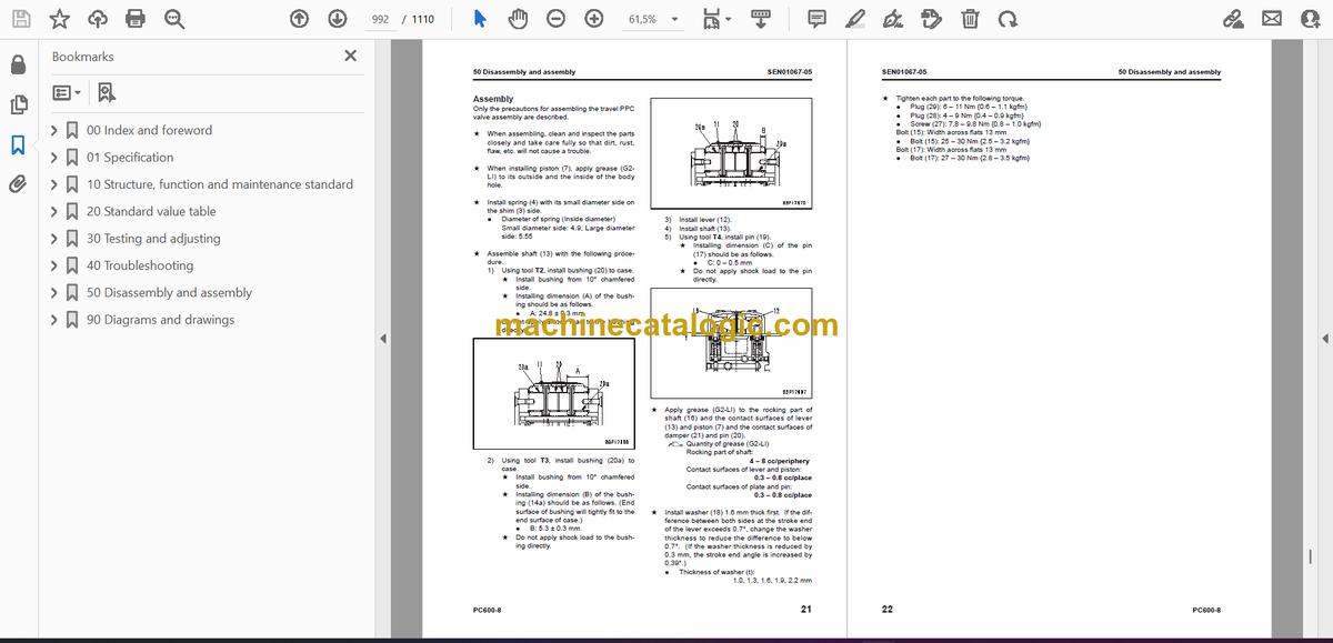
- Disassembly and assembly of work equipment PPC valve assembly
- Disassembly and assembly of travel PPC valve assembly
- Disassembly and assembly of hydraulic cylinder assembly
- Disassembly and assembly of grease gun assembly
- Work equipment
- Removal and installation of bucket cylinder assembly (Backhoe specification)
- Removal and installation of bucket cylinder assembly (Loading shovel specification)
- Removal and installation of arm cylinder assembly (Backhoe specification)
- Removal and installation of arm cylinder assembly (Loading shovel specification)
- Removal and installation of boom cylinder assembly (Backhoe specification)
- Removal and installation of boom cylinder assembly (Loading shovel specification)
- Removal and installation of bottom dump cylinder assembly (Loading shovel specification)
- Removal and installation of bucket assembly (Backhoe specification)
- Removal and installation of bucket assembly (Loading shovel specification)
- Removal and installation of arm assembly (Backhoe specification)
- Removal and installation of arm assembly (Loading shovel specification)
- Removal and installation of boom assembly (Backhoe specification)
- Removal and installation of boom assembly (Loading shovel specification)
- Removal and installation of work equipment (Backhoe specification)
- Removal and installation of work equipment (Loading shovel specification)
- Removal and installation of anti- drop valve assembly for boom
- Removal and installation of anti- drop valve assembly for arm
- Disassembly and assembly anti- drop valve assembly
- Cab and its attachments
- Removal and installation of operator’s cab
- Removal and installation of operator’s cab glass (stuck glass)
- Removal and installation of front window assembly
- Removal and installation of work equipment control lever assembly
- Electrical system
- Removal and installation of air conditioner unit assembly
- Removal and installation of engine controller assembly
- Removal and Installation of KOMTRAX terminal assembly
- Removal and installation of pump controller assembly
- Removal and installation of monitor assembly
- 90 Diagrams and drawings
- Hydraulic diagrams and drawings
- Hydraulic circuit diagram (1/4) (Backhoe specification)
- Hydraulic circuit diagram (2/4) (ATT specification)
- Hydraulic circuit diagram (3/4) (Loading shovel specification)
- Hydraulic circuit diagram (4/4) (Loading shovel specification)
- Electrical diagrams and drawings
- Electrical circuit diagram (1/6)
- Electrical circuit diagram (2/6)
- Electrical circuit diagram (3/6)
- Electrical circuit diagram (4/6)
- Electrical circuit diagram (5/6)
- Electrical circuit diagram (6/6)
- Connector arrangement diagram
- Electrical circuit diagram for air conditioner
Komatsu


