Format: PDF (Printable Document)
File Language: English
File Pages: 172
File Size: 7.62 MB (Speed Download Link)
Brand: Komatsu
Model: PC600-8R PC600LC-8R
Book No: GEN00065-02
Serial No: 60001 and up
Type of Document: Shop Manual
$ 39
Specifications………………………………………………………………………………………………………. 1
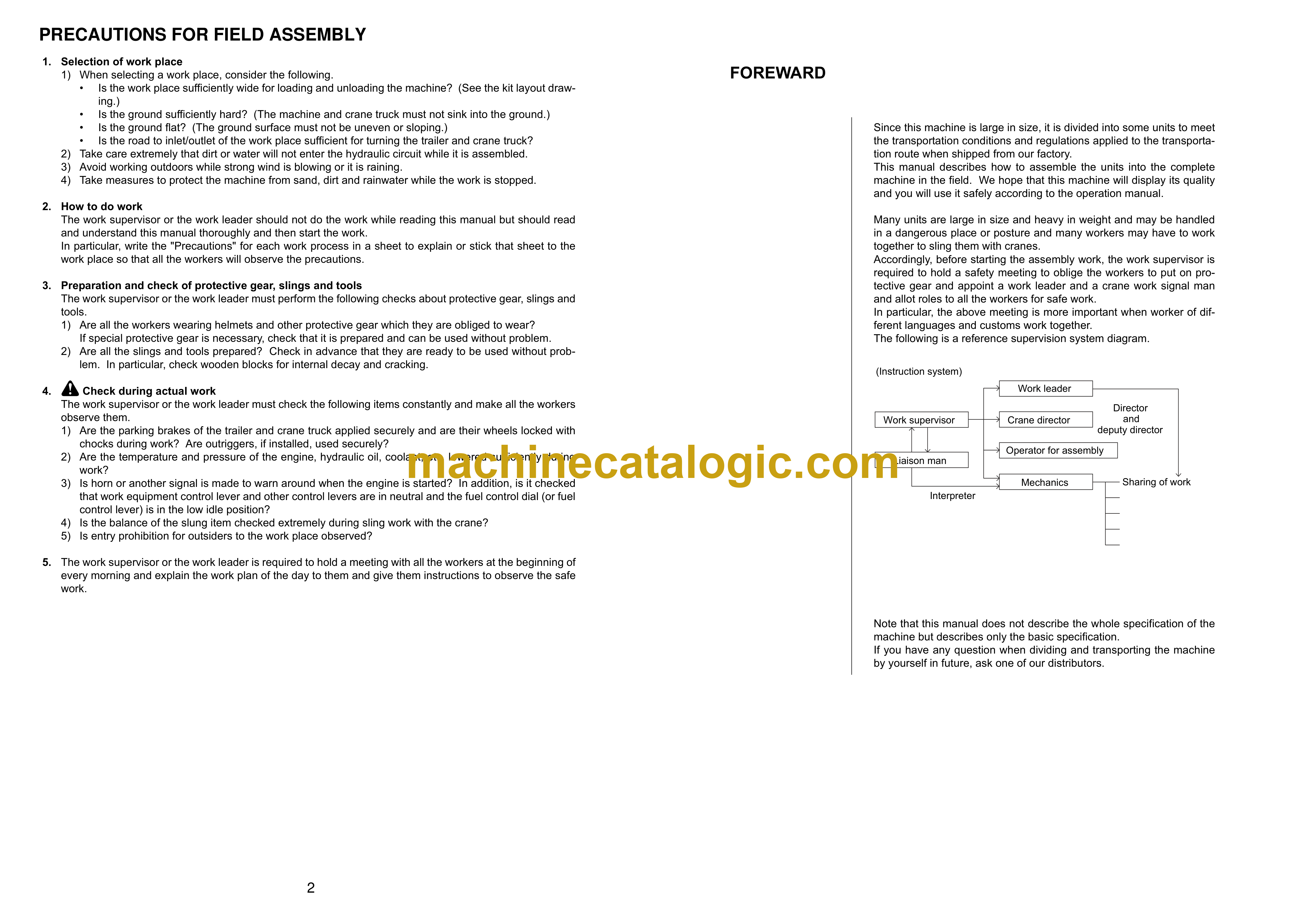
Field Assembling …………………………………………………………………………………………………. 2
Assembling Procedures, Applicable Equipment and Schedule …………………………………… 3
Kit Layout Diagram………………………………………………………………………………………………. 4
Transportation……………………………………………………………………………………………………… 5
List of Tools for Field Assembling…………………………………………………………………………… 10
Standard Tightening Torque ………………………………………………………………………………….. 11
A. Assembly of Chassis ………………………………………………………………………………………… 17
A- 1. Installation of Left and Right Track Frames ………………………………………………….. 18
A- 2. Installation of Travel Pipe ………………………………………………………………………….. 22
A- 3. Installation of Operator Cab’s Left Handrail………………………………………………….. 24
A- 4. Installation of Operator Cab’s Door Stopper and Striker ……………………………….. 25
A- 5. Installation of Rearview Mirror ……………………………………………………………………. 27
A- 6. Installation of Handrail ………………………………………………………………………………. 31
A- 7. Installation of Step ……………………………………………………………………………………. 34
A- 8. Installation of Left Side Step ………………………………………………………………………. 35
A- 9. Sticking Sheet to Counterweight…………………………………………………………………. 36
A-10. Installation of Counterweight ……………………………………………………………………… 37
A-11. Installation of Step Light ……………………………………………………………………………. 38
A-12. Installation of Travel Piping Cover………………………………………………………………. 40
A-13. Installation of Pre-cleaner………………………………………………………………………….. 44
A-14. Testing Track Shoe Tension………………………………………………………………………. 45
A-15. Check Fuel, Coolant and Oil Levels ……………………………………………………………. 48
B. Assembling of Work Equipment …………………………………………………………………………. 51
B- 1. Assembly of Arm Cylinder …………………………………………………………………………. 52
B- 2. Connection of Arm Cylinder Hoses……………………………………………………………… 53
B- 3. Installation of Boom Cylinder ……………………………………………………………………… 54
B- 4. Assembly of Boom Assembly …………………………………………………………………….. 55
B- 5. Installation of Boom Cylinder Hoses……………………………………………………………. 56
B- 6. Installation of Hoses from Chassis Along Top of Boom………………………………….. 57
B- 7. Connection of Boom Cylinder Head ……………………………………………………………. 58
B- 8. Installation of Arm Assembly ……………………………………………………………………… 59
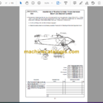
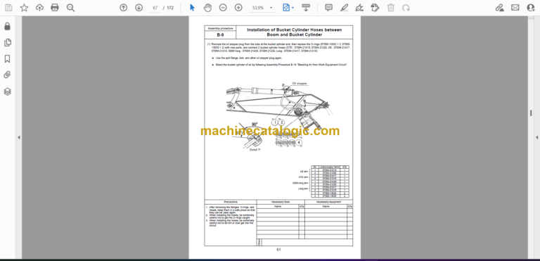
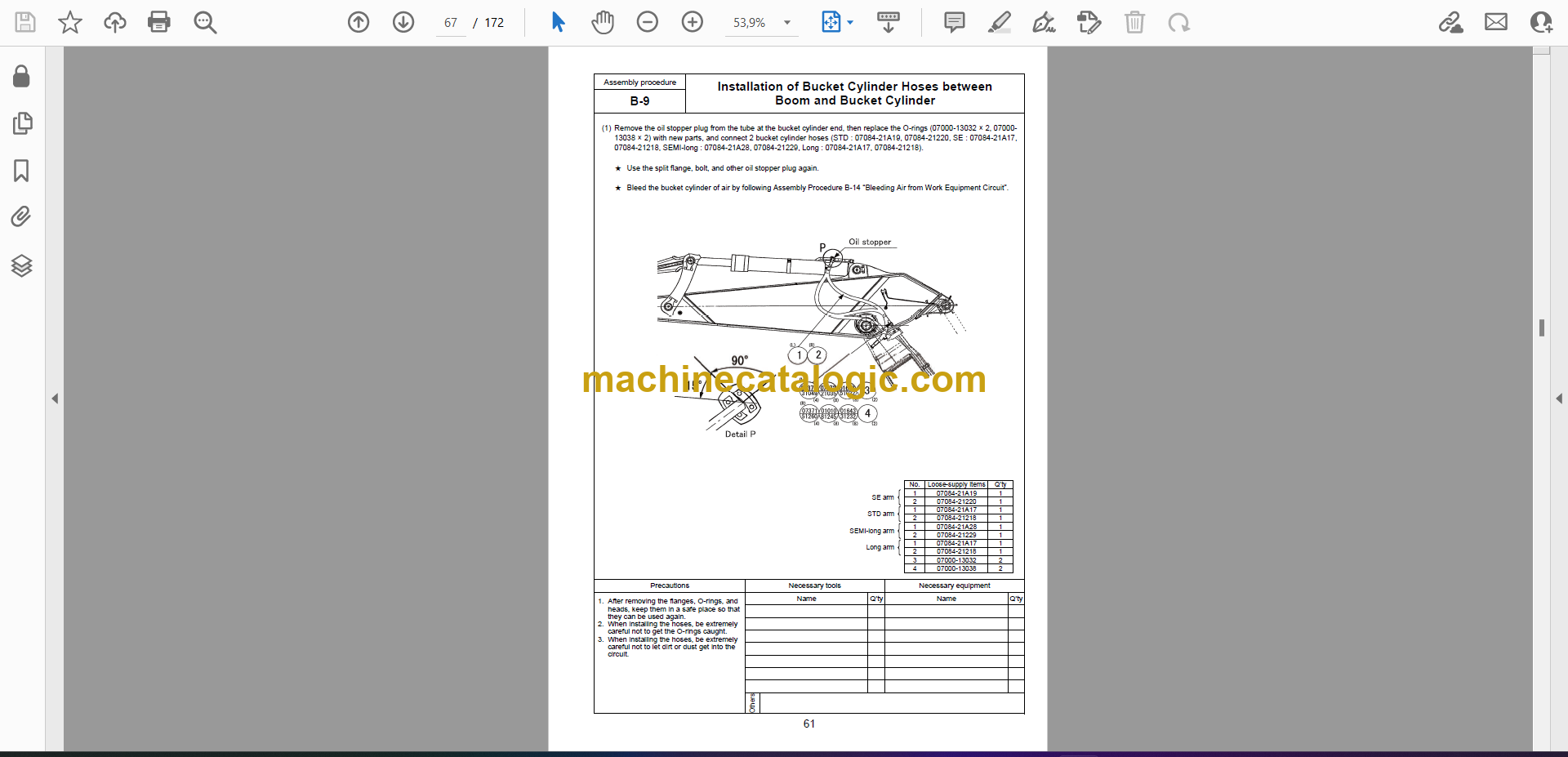
B- 9. Installation of Bucket Cylinder Hoses between Boom and Bucket Cylinder ………. 61
B-10. Installation of Bucket ………………………………………………………………………………… 62
B-11. Connection of Work Equipment Grease Piping …………………………………………….. 63
B-12. Connection of Work Equipment Wiring………………………………………………………… 64
B-13. Greasing after Assembling Work Equipment………………………………………………… 66
B-14. Bleeding Air from Work Equipment Circuit …………………………………………………… 67
B-15. Parts to be Touched up After Field Assembly ………………………………………………. 68
M. Procedure for Inspection and Maintenance after Completion of Assembly ………………. 69
M- 1. Inspection of Oil Level in Hydraulic Tank and Refill ………………………………………. 70
M- 2. Replacement of Return Filter (Standard Filter to Flushing Filter)…………………….. 72
M- 3. Flushing of Hydraulic Circuit ……………………………………………………………………… 75
M- 4. Error Code………………………………………………………………………………………………. 77
M- 5. Operating Method of Monitoring…………………………………………………………………. 82
C. Assembly of Loading Shovel Work Equipment…………………………………………………… 87
C- 1. Releasing Residual Pressure in Hydraulic Circuit……………………………………….. 88
C- 2. Pulling Out Boom Foot Pin and Boom Cylinder Foot Pin……………………………… 89
C- 3. Installation of Boom Cylinder Foot ……………………………………………………………. 90
C- 4. Installation of Boom and Arm Assembly ……………………………………………………. 91
C- 5. Installation of Boom Cylinder Hoses …………………………………………………………. 92
C- 6. Installation of Boom Cylinder Rod Pin……………………………………………………….. 93
C- 7. Installation of Boom Cylinder …………………………………………………………………… 94
C- 8. Installation of Arm Cylinder Hoses ……………………………………………………………. 95
C- 9. Installation of Bucket Cylinder………………………………………………………………….. 96
C-10. Installation of Bucket Cylinder Hose …………………………………………………………. 97
C-11. Installation of Connecting Hoses between Chassis and Boom Top ………………. 98
C-12. Installation of Bottom Dump Cylinder Hoses ……………………………………………… 99
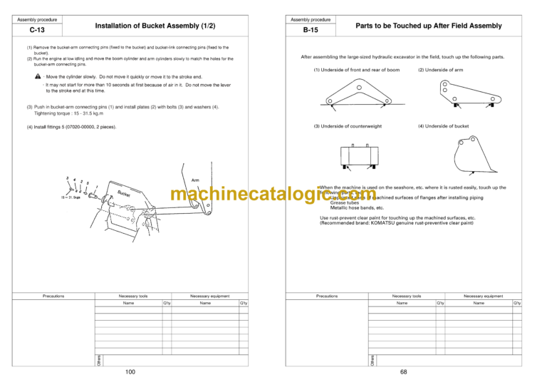
C-13. Installation of Bucket Assembly ……………………………………………………………….. 100
C-14. Installation of Working Lamps………………………………………………………………….. 102
C-15. Installation of Work Equipment Grease Piping …………………………………………… 104
C-16. Greasing After Assembling of Work Equipment………………………………………….. 105
C-17. Bleeding Air from Work Equipment Circuit…………………………………………………. 106
C-18. Checking Oil Level in Hydraulic Tank and Adding Oil………………………………….. 107
C-19. Replacement of Return Filter (Standard Filter to Flushing Filter) ………………….. 108
C-20. Flushing of Hydraulic Circuit ……………………………………………………………………. 111
Field Assembly Inspection Report (Backhoe)
Field Assembly Inspection Report (Loading Shovel)


