These Komatsu PC600-8R1, PC600LC-8R1, PC700LC-8R Crawler Excavators are big production machines for quarry, demolition, and heavy earthmoving work, where downtime burns money fast. People who reach for a Shop Manual like SEN05660-12 are usually planning real repair work, not just daily checks. They want factory procedures so jobs are done once, done right, and parts and labor are lined up in advance.
What this manual helps you do
- Trace hydraulic issues on the PC600-8R1, PC600LC-8R1, and PC700LC-8R using system layouts and step‑by‑step test sequences.
- Diagnose engine, fuel, and electrical faults with guided checks so you’re not guessing or just swapping parts.
- Follow teardown and reassembly procedures for major components like swing, travel, boom/arm cylinders, and final drives.
- Verify adjustment points (linkages, travel, swing, pilot controls) so the machine works to spec after repairs.
- Handle planned overhauls by seeing what’s involved, what tools you’ll need, and which jobs are realistic for your shop.
The Shop Manual for Komatsu PC600-8R1, PC600LC-8R1, PC700LC-8R Crawler Excavator walks through diagnostic procedures, disassembly sequences, and reference torque tables used during workshop-level repairs. The Komatsu PC600-8R1, PC600LC-8R1, PC700LC-8R Crawler Excavator Shop Manual (SEN05660-12) usually covers hydraulic, electrical, powertrain, and structural repair work aimed at dealer or serious independent shops.
Who this is for
If you’re a field tech, shop mechanic, or fleet manager planning in‑house repairs, this is the right level of detail. Operators or trainees looking for basic controls, safety, and daily service would be better off with the Operation & Maintenance Manual instead.
FAQ
Q: Is this a searchable PDF I can print from?
A: Yes, it’s typically a PDF you can search by keyword and print specific sections for the job.
Q: Is this enough for full rebuild work, or just light service?
A: This is a workshop‑level shop manual, so it’s aimed at full diagnostic and repair tasks, not just basic maintenance.
Q: How do I know if it matches my serial number or machine variant?
A: Check your machine ID plate and confirm it matches the PC600-8R1, PC600LC-8R1, or PC700LC-8R family and the SEN05660-12 reference before you buy.
Bottom line: If you’re planning to actually tear into these excavators and want to control downtime and parts planning, grab this manual; if you only need operating instructions or service intervals, keep looking for the O&M book instead.
📘 Show Index
Table of Contents:
- 00 Index and foreword
- Table of Contents
- Foreword, safety and general information
- Important safety notice
- How to read the shop manual
- Explanation of terms for maintenance standard
- Handling equipment of fuel system devices
- Handling of intake system parts
- Handling of hydraulic components
- Method of disconnecting and connecting push-pull type coupler
- Handling of electric equipment
- How to read electric wire code
- Precautions when performing operation
- Practical use of KOMTRAX
- Precautions when performing work
- Standard tightening torque table
- List of abbreviation
- Conversion table
- 01 Specification
- Contents
- Specifications
- Specifications drawing
- Working range drawings
- Specifications
- Table of weight
- Table of fuel, coolant and lubricants
- 10 Structure and function
- Contents
- Engine and cooling system
- Engine related parts
- PTO
- Cooling system
- Power train system
- Power train
- Swing circle
- Swing machinery
- Final drive
- Undercarriage and frame
- Track frame and idler cushion
- Hydraulic system
- Hydraulic component layout
- Valve control
- Hydraulic tank and filter
- Hydraulic pump (piston pump)
- Cooling fan pump
- Cooling fan motor
- Control valve
- Swing motor
- Travel motor
- PPC valve
- Solenoid valve
- PPC shuttle valve
- Boom drift prevention valve
- Boom LOWER regeneration valve
- Arm regeneration valve
- Quick return valve
- Line oil filter
- Center swivel joint
- Accumulator
- Electrical system
- Engine control
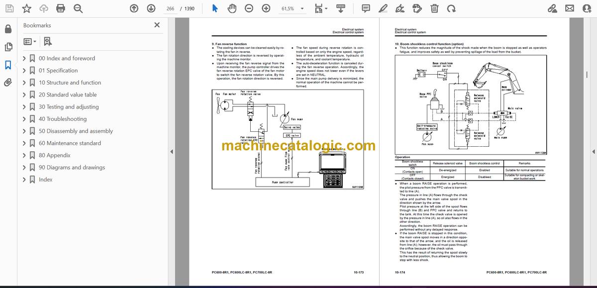
- Electrical control system
- Monitor system
- KOMTRAX system
- Sensors
- 20 Standard value table
- Contents
- Standard value table
- Standard value table for engine
- Standard value table for machine
- 30 Testing and adjusting
- Contents
- Tool for testing, adjusting and troubleshooting
- Tools for testing, adjusting, and troubleshooting
- Engine and cooling system
- Testing engine speed
- Testing intake air pressure (boost pressure)
- Testing exhaust gas temperature
- Testing exhaust gas color
- Testing and adjusting valve clearance
- Testing compression pressure
- Testing blowby pressure
- Testing engine oil pressure
- Handling fuel system parts
- Releasing remaining pressure from fuel system
- Testing fuel pressure
- Cylinder cut-out test mode
- No-injection cranking
- Testing fuel return rate and leakage
- Bleeding air from fuel circuit
- Testing fuel circuit for leakage
- Testing and adjusting alternator belt tension
- Testing and adjusting air conditioner compressor belt tension
- Undercarriage and frame
- Testing swing circle bearing clearance
- Checking and adjusting track tension
- Hydraulic system
- Testing and adjusting oil pressure in work equipment, swing and travel circuits
- Testing and adjusting control circuit oil pressure
- Testing and adjusting control oil pressure of piston pump
- Testing servo piston movement
- Testing PPC valve output pressure
- Testing output pressure of solenoid valve and PPC shuttle valve
- Adjusting play of work equipment and swing PPC vavles
- Isolating the parts causing hydraulic drift in work equipment
- Testing and adjusting travel deviation
- Testing fan speed
- Testing fan circuit oil pressure
- Releasing remaining pressure from hydraulic circuit
- Testing oil leakage
- Bleeding air from each part
- Electrical system
- Special functions of machine monitor
- Handling of voltage circuit of engine controller
- Preparatory work for troubleshooting of electrical system
- Inspection procedure of diode
- Pm clinic
- Pm Clinic service
- UNDERCARRIAGE INSPECTION REPORT
- 40 Troubleshooting
- Contents
- General information on troubleshooting
- Points to remember when troubleshooting
- Sequence of events in troubleshooting
- Checks before troubleshooting
- Classification and procedures for troubleshooting
- Failure codes table
- Symptom and troubleshooting numbers
- Information in troubleshooting table
- Troubleshooting method for open circuit in wiring harness of pressure sensor system
- Connector list and layout
- Connection table for connector pin numbers
- T- branch box and T- branch adapter table
- Fuse locations
- Troubleshooting by failure code
- Failure code [989L00] Engine Controller Lock Caution 1
- Failure code [989M00] Engine Controller Lock Caution 2
- Failure code [989N00] Engine Controller Lock Caution 3
- Failure code [AA10NX] Air Cleaner Clogging
- Failure code [AB00KE] Charge Voltage Low
- Failure code [B@BAZG] Eng Oil Press Low
- Failure code [B@BAZK] Eng Oil Level Low
- Failure code [B@BCNS] Eng Water Overheat
- Failure code [B@BCZK] Eng Water Level Low
- Failure code [B@HANS] Hyd Oil Overheat
- Failure code [CA111] ECM Critical Internal Failure
- Failure code [CA115] Eng Ne and Bkup Speed Sens Error
- Failure code [CA122] Chg Air Press Sensor High Error
- Failure code [CA123] Chg Air Press Sensor Low Error
- Failure code [CA131] Throttle Sensor High Error
- Failure code [CA132] Throttle Sensor Low Error
- Failure code [CA135] Eng Oil Press Sensor High Error
- Failure code [CA141] Eng Oil Press Sensor Low Error
- Failure code [CA144] Coolant Temp Sens High Error
- Failure code [CA145] Coolant Temp Sens Low Error
- Failure code [CA153] Chg Air Temp Sensor High Error
- Failure code [CA154] Chg Air Temp Sensor Low Error
- Failure code [CA187] Sens Supply 2 Volt Low Error
- Failure code [CA221] Ambient Press Sens High Error
- Failure code [CA222] Ambient Press Sens Low Error
- Failure code [CA227] Sens Supply 2 Volt High Error
- Failure code [CA234] Eng Overspeed
- Failure code [CA238] NE Speed Sens Supply Volt Error
- Failure code [CA263] Fuel Temp Sensor High Error
- Failure code [CA265] Fuel Temp Sensor Low Error
- Failure code [CA271] IMV/PCV1 Short Error
- Failure code [CA272] IMV/PCV1 Open Error
- Failure code [CA273] PCV2 Short Error
- Failure code [CA274] PCV2 Open Error
- Failure code [CA322] Inj #1(L#1) Open/Short Error
- Failure code [CA323] Inj #5 (L#5) Open/Short Error
- Failure code [CA324] Inj #3(L#3) Open/Short Error
- Failure code [CA325] Inj #6 (L#6) Open/Short Error
- Failure code [CA331] Inj #2(L#2) Open/Short Error
- Failure code [CA332] Inj #4 (L#4) Open/Short Error
- Failure code [CA342] Calibration Code Incompatibility
- Failure code [CA351] Injectors Drive Circuit Error
- Failure code [CA352] Sens Supply 1 Volt Low Error
- Failure code [CA386] Sens Supply 1 Volt High Error
- Failure code [CA441] Battery Voltage Low Error
- Failure code [CA442] Battery Voltage High Error
- Failure code [CA449] Rail Press Very High Error
- Failure code [CA451] Rail Press Sensor High Error
- Failure code [CA452] Rail Press Sensor Low Error
- Failure code [CA553] Rail Press High Error
- Failure code [CA554] Rail Press Sensor In Range Error
- Failure code [CA559] Supply Pump Press Low Error 1
- Failure code [CA689] Eng NE Speed Sensor Error
- Failure code [CA731] Eng Bkup Speed Sens Phase Error
- Failure code [CA757] All Continuous Data Lost Error
- Failure code [CA778] Eng Bkup Speed Sensor Error
- Failure code [CA1633] KOMNET Datalink Timeout Error
- Failure code [CA2185] Throt Sens Sup Volt High Error
- Failure code [CA2186] Throt Sens Sup Volt Low Error
- Failure code [CA2249] Rail Press Very Low Error
- Failure code [CA2555] Grid Htr Relay Open Circuit Error
- Failure code [CA2556] Grid Htr Relay Short Circuit Error
- Failure code [D110KB] Battery Relay Drive Short Circuit
- Failure code [D163KB] Flash Light Relay Short Circuit
- Failure code [D195KA] Step Light Relay Open Circuit
- Failure code [D195KB] Step Light Relay Short Circuit
- Failure code [D19JKZ] Personal code relay abnormality
- Failure code [D862KA] GPS Antenna Open Circuit
- Failure code [DA22KK] Pump Solenoid Power Low Error
- Failure code [DA25KP] 5V Sensor1 Power Abnormality
- Failure code [DA29KQ] Model Selection Abnormality
- Failure code [DA2RMC] CAN Discon (Pump Con Detected)
- Failure code [DA80MA] Auto. Lub. Abnormal.
- Failure code [DAF8KB] Camera Power Supply Short Circuit
- Failure code [DAFGMC] GPS Module Error
- Failure code [DAFRMC] CAN Discon (Monitor Detected)
- Failure code [DGE5KB] Ambi. Temp Sensor Short Circuit
- Failure code [DGH2KB] Hyd Oil Sensor Short
- Failure code [DHPAMA] F Pump Press Sensor Abnormality
- Failure code [DHPBMA] R Pump Press Sensor Abnormality
- Failure code [DV20KB] Travel alarm short circuit
- Failure code [DW43KA] Travel Speed Sol Open Circuit
- Failure code [DW43KB] Travel Speed Sol Short Circuit
- Failure code [DW45KA] Swing Brake Sol Open Circuit
- Failure code [DW45KB] Swing Brake Sol Short Circuit
- Failure code [DW48KA] CO Cancel Sol Open Circuit
- Failure code [DW48KB] CO Cancel Sol Short Circuit
- Failure code [DW4XKA] Bucket Curl Hi Cancel Sol Open Circuit
- Failure code [DW4XKB] Bucket Curl Hi Cancel Sol Short Circuit
- Failure code [DW7BKA] Fan Reverse Sol Open Circuit
- Failure code [DW7BKB] Fan Reverse Sol Short Circuit
- Failure code [DWK0KA] 2-stage Relief Sol Open Circuit
- Failure code [DWK0KB] 2-stage Relief Sol Short Circuit
- Failure code [DX16KA] Fan Pump EPC Sol Open Circuit
- Failure code [DX16KB] Fan Pump EPC Sol Short Circuit
- Failure code [DXA0KA] TVC Sol Open Circuit
- Failure code [DXA0KB] TVC Sol Short Circuit
- Failure code [DY20KA] Wiper Working Abnormality
- Failure code [DY20MA] Wiper Parking Abnormality
- Failure code [DY2CKA] Washer Drive Open Circuit
- Failure code [DY2CKB] Washer Drive Short Circuit
- Failure code [DY2DKB] Wiper Drive (Fwd) Short Circuit
- Failure code [DY2EKB] Wiper Drive (Rev) Short Circuit
- Failure code [DY2FMA] Upper Wiper Working Abnormality
- Failure code [DY2GKM] Wiper Select Abnormality
- Troubleshooting of electrical system (E-mode)
- E-1 Engine does not start (Engine does not crank)
- E-2 Preheater does not operate
- E-3 When starting switch is turned to ON position, machine monitor displays nothing
- E-4 When starting switch is turned to ON position (before starting engine), basic check monitor lights up.
- E-5 Precaution item lights up while engine is running
- E-6 Emergency stop item lights up while engine is running
- E-7 Engine coolant temperature gauge does not indicate properly
- E-8 Fuel gauge does not indicate properly
- E-9 Hydraulic oil temperature gauge does not indicate properly
- E-10 Content of display on machine monitor is different from that of actual machine
- E-11 Some areas of machine monitor screen are not displayed
- E-12 Function switch does not operate
- E-13 Automatic warm-up system does not operate (in cold season)
- E-14 Auto-decelerator does not operate properly
- E-15 Working mode does not change
- E-16 Travel speed does not change
- E-17 Alarm buzzer cannot be canceled
- E-18 When starting switch is turned OFF, service meter is not displayed
- E-19 Service mode cannot be selected
- E-20 Any of work equipment, swing and travel does not work or cannot be locked
- E-21 Machine push-up function does not work or cannot be canceled
- E-22 Boom shockless function does not operate normally
- E-23 Swing brake does not operate normally
- E-24 Windshield wiper and window washer do not operate
- E-25 Travel alarm does not sound or does not stop sounding
- E-26 BOOM RAISE indicator is not displayed properly with monitoring function
- E-27 BOOM LOWER indicator is not displayed properly with monitoring function
- E-28 ARM IN indicator is not displayed properly with monitoring function
- E-29 ARM DUMP indicator is not displayed properly with monitoring function
- E-30 BUCKET CURL indicator is not displayed properly with monitoring function
- E-31 BUCKET DUMP indicator is not displayed properly with monitoring function
- E-32 Swing indicator is not displayed properly with monitoring function
- E-33 Travel indicator is not displayed properly with monitoring function
- E-34 "Service" is not displayed normally by monitoring function
- E-35 Electric grease gun does not operate
- E-36 KOMTRAX system does not operate normally
- E-37 Bottom dump does not operate properly
- E-38 Horn does not sound or does not stop sounding
- E-39 Step light does not light up or go off
- Troubleshooting of hydraulic and mechanical system (H-mode)
- Before troubleshooting for hydraulic and mechanical systems
- Information in troubleshooting table (H-mode)
- H-1 All of work equipment, travel and swing work slow or lack power
- H-2 Engine speed lowers significantly or engine stalls
- H-3 Any of work equipment, swing and travel does not work
- H-4 Unusual noise is heard from around hydraulic pump
- H-5 Auto-decelerator is not canceled
- H-6 Speed or power of boom is low
- H-7 Speed or power of arm is low
- H-8 Speed or power of bucket is low
- H-9 Boom does not move
- H-10 Arm does not move
- H-11 Bucket does not move
- H-12 Bottom dump does not move
- H-13 Hydraulic drift of work equipment is large
- H-14 Time lag of work equipment is large
- H-15 One-touch power maximizing function does not work or is not canceled
- H-16 Machine push-up function does not work or is not canceled
- H-17 Boom/bucket speed is low at combined operation of arm and boom or bucket
- H-18 Speed of boom, arm, swing and travel is low at combined operation of bucket and boom, arm, swing and travel
- H-19 Swing speed is low at combined operation of arm and swing.
- H-20 Machine deviates during travel
- H-21 Machine deviates significantly at start
- H-22 Machine deviates significantly during combined operation
- H-23 Travel speed or travel power is low
- H-24 One of tracks does not run (on 1 side alone)
- H-25 Travel speed does not change
- H-26 Upper structure does not swing
- H-27 Swing speed is low or acceleration is poor
- H-28 Upper structure overruns excessively when it stops swinging
- H-29 Shock is large when upper structure stops swinging
- H-30 Large unusual noise is heard when upper structure stops swinging
- H-31 Hydraulic drift of swing is large
- Troubleshooting of engine (S-mode)
- Method of using troubleshooting chart
- S-1 Startability is poor
- S-2 Engine does not start
- S-3 Engine does not pick up smoothly
- S-4 Engine stops during operation
- S-5 Engine runs rough or is unstable
- S-6 Engine lacks power
- S-7 Exhaust smoke is black (incomplete combustion)
- S-8 Oil consumption is excessive (or exhaust smoke is blue)
- S-9 Oil becomes contaminated early
- S-10 Fuel consumption is excessive
- S-11 Oil is in coolant (or coolant spurts or coolant level goes down)
- S-12 Oil pressure drops
- S-13 Oil level rises (coolant or fuel in oil)
- S-14 Coolant temperature rises too high (overheating)
- S-15 Unusual noise is made
- S-16 Vibration is excessive
- 50 Disassembly and assembly
- Contents
- General information on disassembly and assembly
- How to read this manual
- Coating materials list
- Special tools list
- Sketches of special tools
- Engine and cooling system
- Removal and installation of fuel supply pump assembly
- Removal and installation of fuel injector assembly
- Removal and installation of cylinder head assembly
- Removal and installation of radiator assembly
- Removal and installation of hydraulic oil cooler assembly
- Removal and installation of aftercooler assembly
- Removal and installation of engine front seal
- Removal and installation of engine rear seal
- Removal and installation of engine, PTO and hydraulic pump assembly
- Removal and installation of cooling fan motor assembly
- Removal and installation of fuel tank assembly
- Power train
- Removal and installation of PTO assembly
- Disassembly and assembly of PTO assembly
- Disassembly and assembly of final drive assembly
- Removal and installation of swing motor and swing machinery assembly
- Disassembly and assembly of swing machinery assembly
- Removal and installation of swing circle assembly
- Undercarriage and frame
- Separation and connection of track shoe assembly
- Disassembly and assembly of one link in field
- Removal and installation of idler assembly
- Disassembly and assembly of idler assembly
- Removal and installation of idler cushion assembly
- Disassembly and assembly of idler cushion assembly
- Removal and installation of track roller assembly
- Disassembly and assembly of track roller assembly
- Removal and installation of carrier roller assembly
- Disassembly and assembly of carrier roller assembly
- Removal and installation of revolving frame assembly
- Removal and installation of counterweight assembly
- Removal and installation of counterweight remover assembly
- Hydraulic system
- Removal and installation of center swivel joint assembly
- Disassembly and assembly of center swivel joint assembly
- Removal and installation of hydraulic tank assembly
- Removal and installation of hydraulic pump assembly
- Removal and installation of control valve assembly
- Disassembly and assembly of control valve assembly
- Removal and installation of swing motor assembly
- Disassembly and assembly of work equipment PPC valve assembly
- Disassembly and assembly of travel PPC valve assembly
- Disassembly and assembly of grease gun assembly
- Work equipment
- Removal and installation of bucket cylinder assembly
- Removal and installation of arm cylinder assembly
- Removal and installation of boom cylinder assembly
- Removal and installation of bottom dump cylinder assembly
- Removal and installation of bucket assembly
- Removal and installation of arm assembly
- Removal and installation of boom assembly
- Removal and installation of work equipment assembly
- Disassembly and assembly of work equipment cylinder assembly
- Cab and its attachments
- Removal and installation of operator's cab assembly
- Removal and installation of operator's cab glass (adhered window glass)
- Removal and installation of front window assembly
- Removal and installation of air conditioner unit assembly
- Removal and installation of work equipment control lever assembly
- Electrical system
- Removal and installation of air conditioner compressor assembly
- Removal and installation of air conditioner condenser assembly
- Removal and installation of engine controller assembly
- Removal and installation of pump controller assembly
- Removal and installation of KOMTRAX terminal assembly
- Removal and installation of machine monitor assembly
- 60 Maintenance standard
- Contents
- Engine and cooling system
- Engine mount
- PTO
- Cooling system
- Power train
- Swing circle
- Swing machinery
- Final drive
- Sprocket
- Undercarriage and frame
- Track frame and idler cushion
- Idler
- Track roller
- Carrier roller
- Track shoe
- Hydraulic system
- Hydraulic pump
- Control valve
- Swing motor
- Travel motor
- PPC valve
- Boom drift prevention valve
- Regeneration valve (boom, arm)
- Center swivel joint
- Work equipment
- Work equipment
- Work equipment dimension
- Work equipment cylinder
- 80 Appendix
- Table of contents
- Air conditioner
- Precautions for refrigerant
- Air conditioner component
- Configuration and function of refrigeration cycle
- Outline of refrigeration cycle
- Air conditioner unit
- Air conditioner controller
- Compressor
- Condenser
- Receiver drier
- Procedure for testing and troubleshooting
- Circuit diagram and arrangement of connector pins
- System diagram
- Detail of air conditioner unit
- Parts and connectors layout
- Testing air leakage (duct)
- Testing with self-diagnosis function
- Testing temperature control
- Testing vent (mode) changeover
- Testing FRESH/RECIRC air changeover
- Testing inner sensor
- Testing evaporator temperature sensor
- Testing sunlight sensor
- Testing (dual) pressure switch for refrigerant
- Testing relays
- Troubleshooting chart 1
- Troubleshooting chart 2
- Information in troubleshooting table
- Troubleshooting for power supply and CAN communication system (Air conditioner does not operate)
- Troubleshooting for compressor and refrigerant system (Air is not cooled)
- Troubleshooting for blower motor system (No air comes out or air flow is abnormal)
- Troubleshooting for temperature control
- Troubleshooting for vent (mode) changeover
- Troubleshooting for FRESH/RECIRC air changeover
- Troubleshooting for temperature sensor system
- Troubleshooting with gauge pressure
- Connection of service tool
- Precautions for disconnecting and connecting air conditioner piping
- Handling of compressor oil
- 90 Diagrams and drawings
- Contents
- Hydraulic circuit diagram
- Symbols used in hydraulic circuit diagrams
- Hydraulic circuit diagram
- Electrical circuit diagram
- Symbols used in electric circuit diagrams
- Electrical circuit diagram
- Air conditioner electrical circuit diagram
- Index
- A
- B
- C
- D
- E
- F
- G
- H
- I
- K
- L
- M
- N
- O
- P
- Q
- R
- S
- T
- U
- V
- W
Komatsu


