Format: PDF (Printable Document)
File Language: English
File Pages: 158
File Size: 5.19 MB (Speed Download Link)
Brand: Komatsu
Model: PC8000
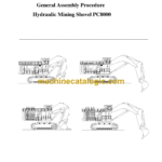
Type of Document: Assembly Procedure Shop Manual
$ 39
1. Mounting of Crawler Segments to the Side Frames: Z22917
2. Assembly of Undercarriage: Z22918
3. Assembly of Cable Reel Unit: Z22919
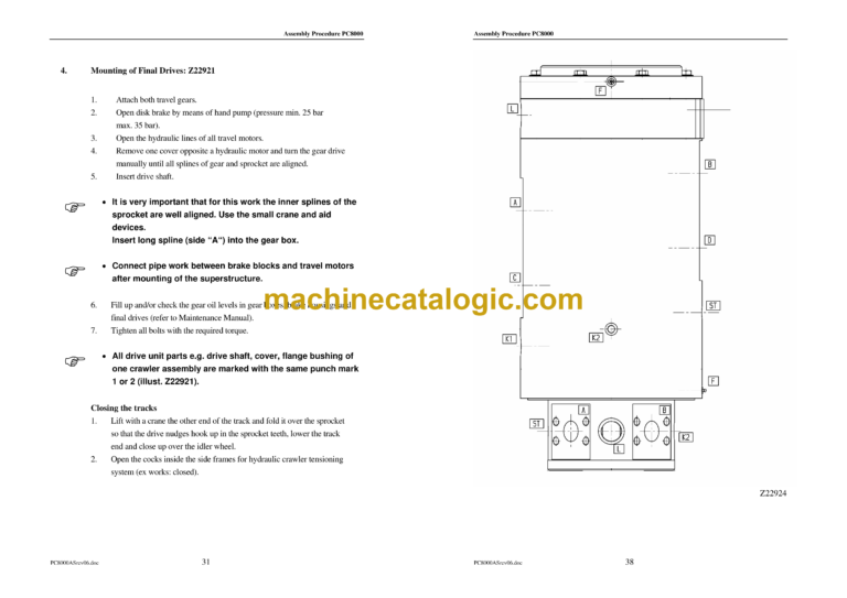
4. Mounting of Final Drives: Z22921
5. Electric drive only: Mounting of auxiliary weight at the undercarriage: Z22993
6. Mounting of Slew Ring underneath the Superstructure Platform: Z22922
7. Assembly of the Superstructure Platform onto the Undercarriage: Z22923
7.1 Rotary Distributor Z22924
8. Assembly of the Prime Drive Unit to the Superstructure Platform: Z22925 /
Z22926
8.1 Overview Drive unit
8.2 Electric drive: Direction of motor rotation; mounting the coupling
9. Preassembly Boom- and Stick Cylinders to the Boom: Z22932
9.1 Preassembly Boom- and Stick Cylinders to the Boom (Backhoe attachment) :
Z23007; Z23008
10. Mounting of Boom Z22933
11. Mounting of Counterweight: Z22934A
12. Mounting the Fuel Tank: Z22935 or Main Switch Cabinet for electric Driven Unit
13.1 Mounting of Cable transfer Z22937
13.2 Mounting of front cover
14. Mounting of Operator’s Cab Z22938; 22939
14.1 Mounting of the Cab air cleaner (Cab support to Cab) Z22940
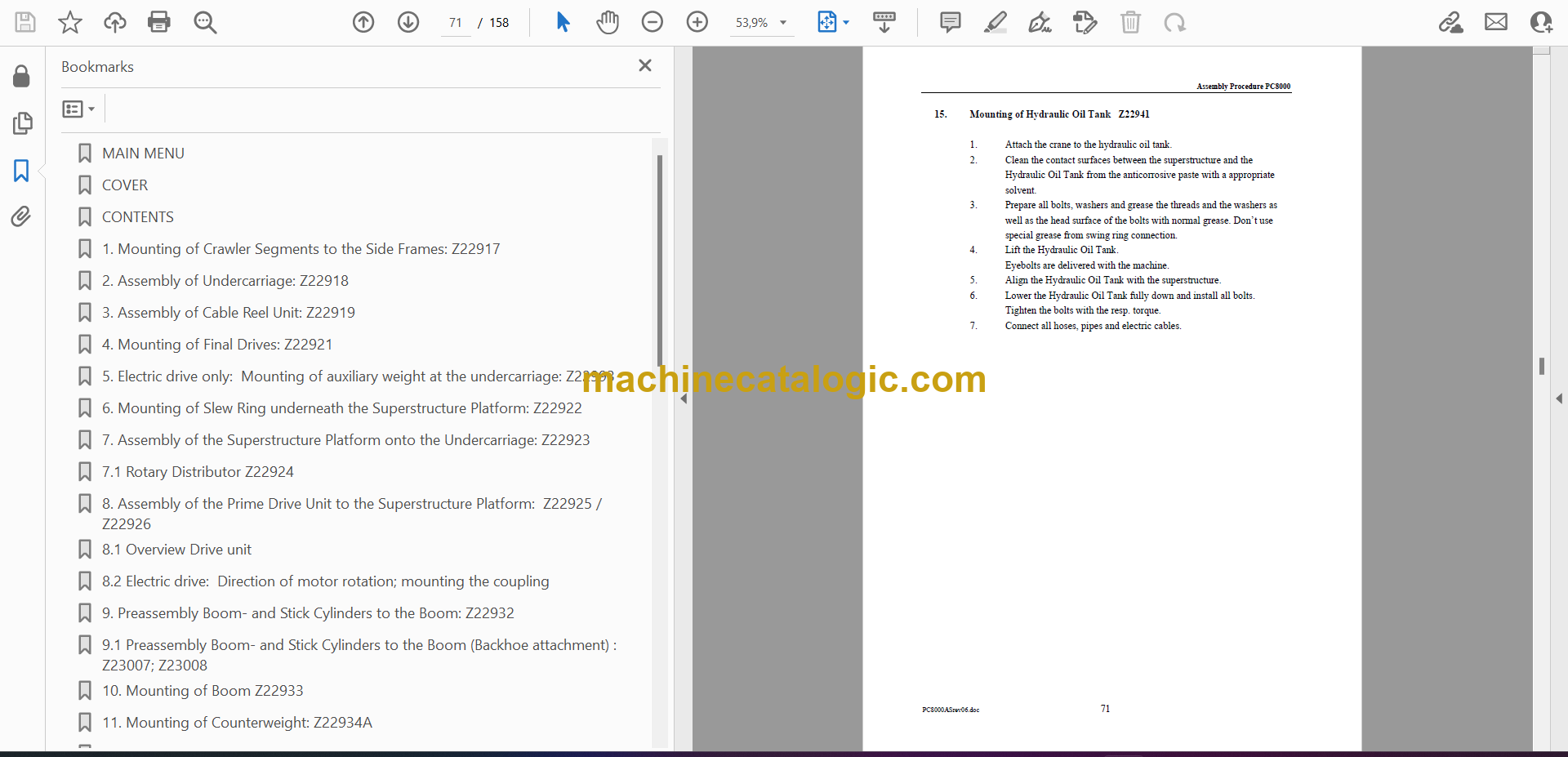
15. Mounting of Hydraulic Oil Tank Z22941
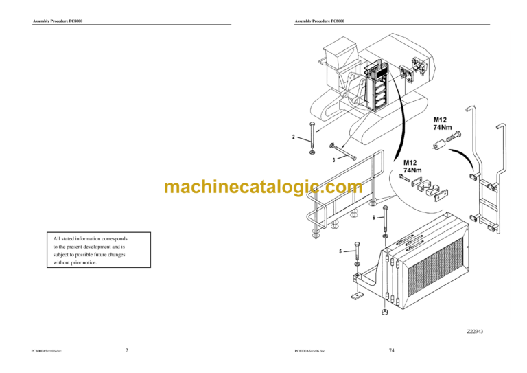
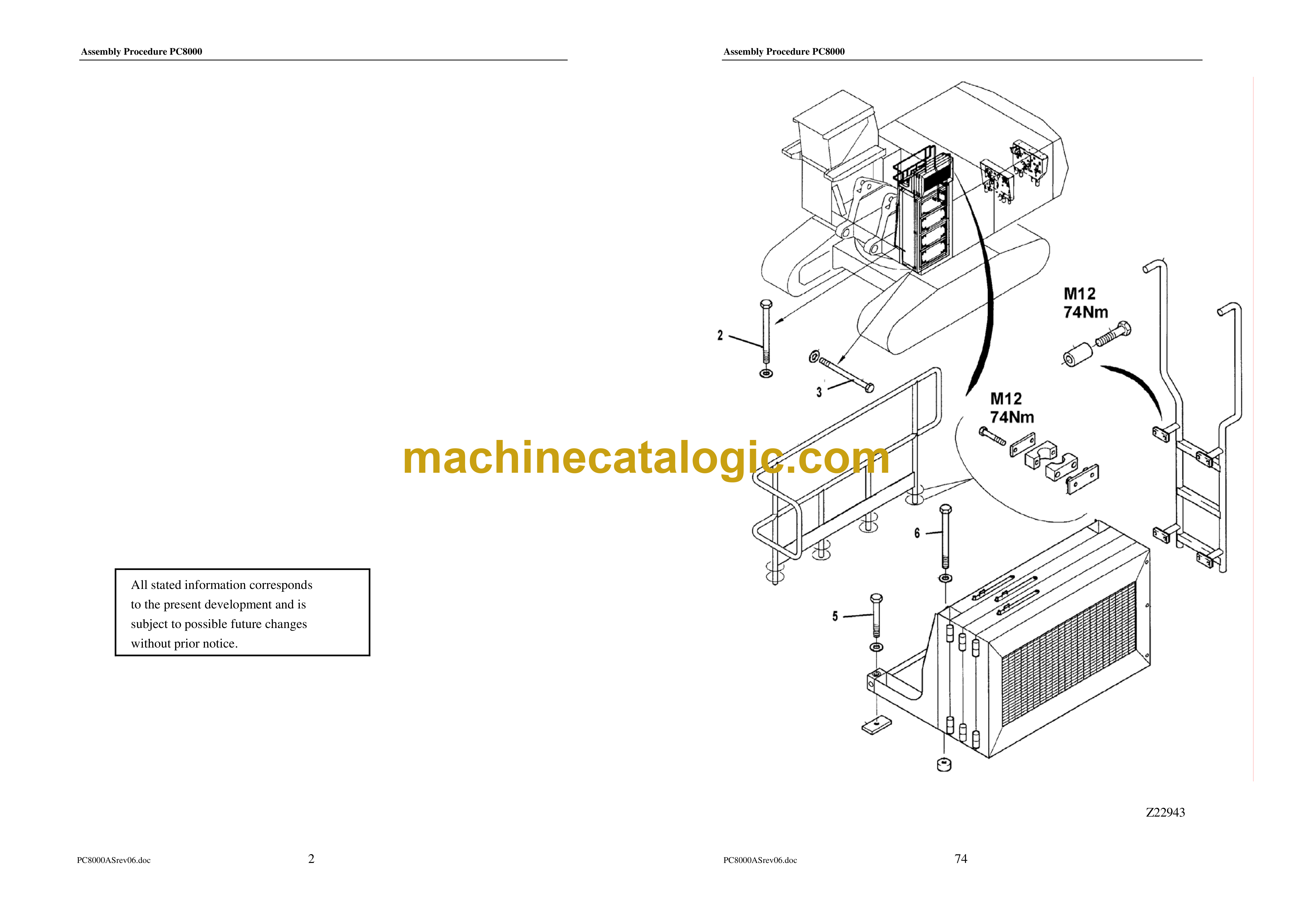
16. Mounting of Hydraulic Oil Coolers Z22942; Z22943
17. Mounting Hand Rails, Cat Walks, Steps, Stairs and Ladders: Z22944; Z22945
18. Install the hydraulic access ladder Z22946
19. Installation of Muffler assy, and Cover: Z22928
20. Installation of Air Filters: Z22929 – Z22931
21. Installation of Lubrication Station and auxiliary Crane Z22947; Z22948
22. Connection of cable harnesses to the X – boards
23. Installation of Hose connections on Hydr. Tank and Hydr. Oil Coolers: Z22949;
Z22950
23.1 Installation of Hose connections on Auxiliary Hydraulic Oil Cooler (Z22951 and
Z22952)
24. Installation of HP- Hoses in between HP – Filters and Main Valve Blocks: Z22953
25. Mounting of Bucket Cylinders : Z22954; 22955
26.1 Mounting of Stick: Z22989 (Backhoe attachment)
27. Installation of Hose connections to the boom: Z22957; Z22958
28. Filling up hydraulic tank Z22959
28.1 Filling up fuel tank
29. Pre-checks for initial Start-up
30. Mounting of Stick Cylinders to the Stick: Z22961
31. Mounting of the Pin Seals
31.1 Mounting of the Pin Seals
32. Assembly of Bullclam Bucket to the Stick (Z21876; Z22962)
32.1 Assembly of Backhoe to the Stick (Z23005)
33. Assembling and testing the Fire Detection, Actuation and Suppression System
34. Checks and Adjustments Prior to Commissioning