$ 39
Safety information ………………………………………………………………………………………………………………… 1
Handling of tie-off anchor points ……………………………………………………………………………………………. 29
Be careful not to hit bucket when retracting work equipment ……………………………………………………… 30
Specifications …………………………………………………………………………………………………………………….. 31
Precautions for field assembly ………………………………………………………………………………………………. 32
Disposal of removed parts ……………………………………………………………………………………………………. 33
Assembly procedure, facility used, and schedule …………………………………………………………………….. 34
Kit layout diagram ………………………………………………………………………………………………………………. 35
Flow of main field assembly …………………………………………………………………………………………………. 36
Transportation packing style …………………………………………………………………………………………………. 37
Field assembly tools list ………………………………………………………………………………………………………. 44
Tightening torque ……………………………………………………………………………………………………………….. 46
Coating materials ……………………………………………………………………………………………………………….. 51
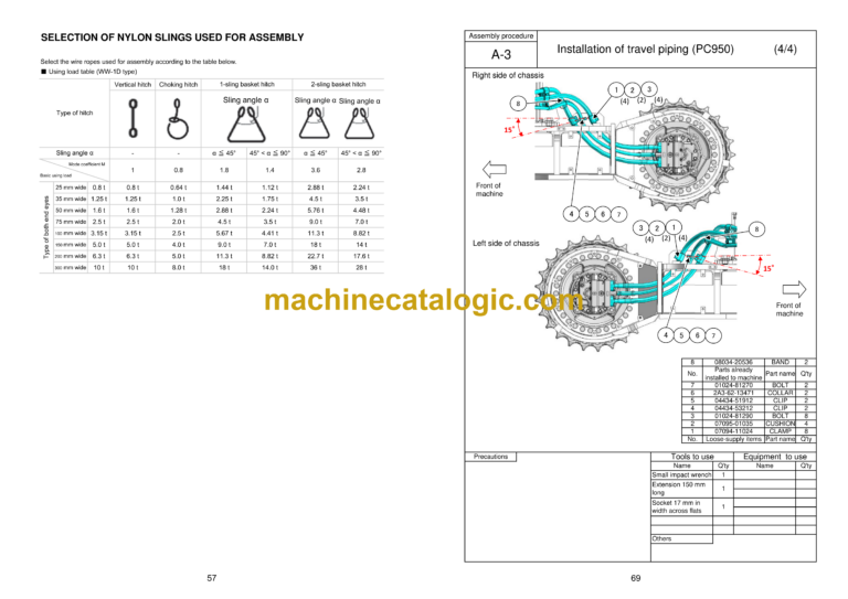
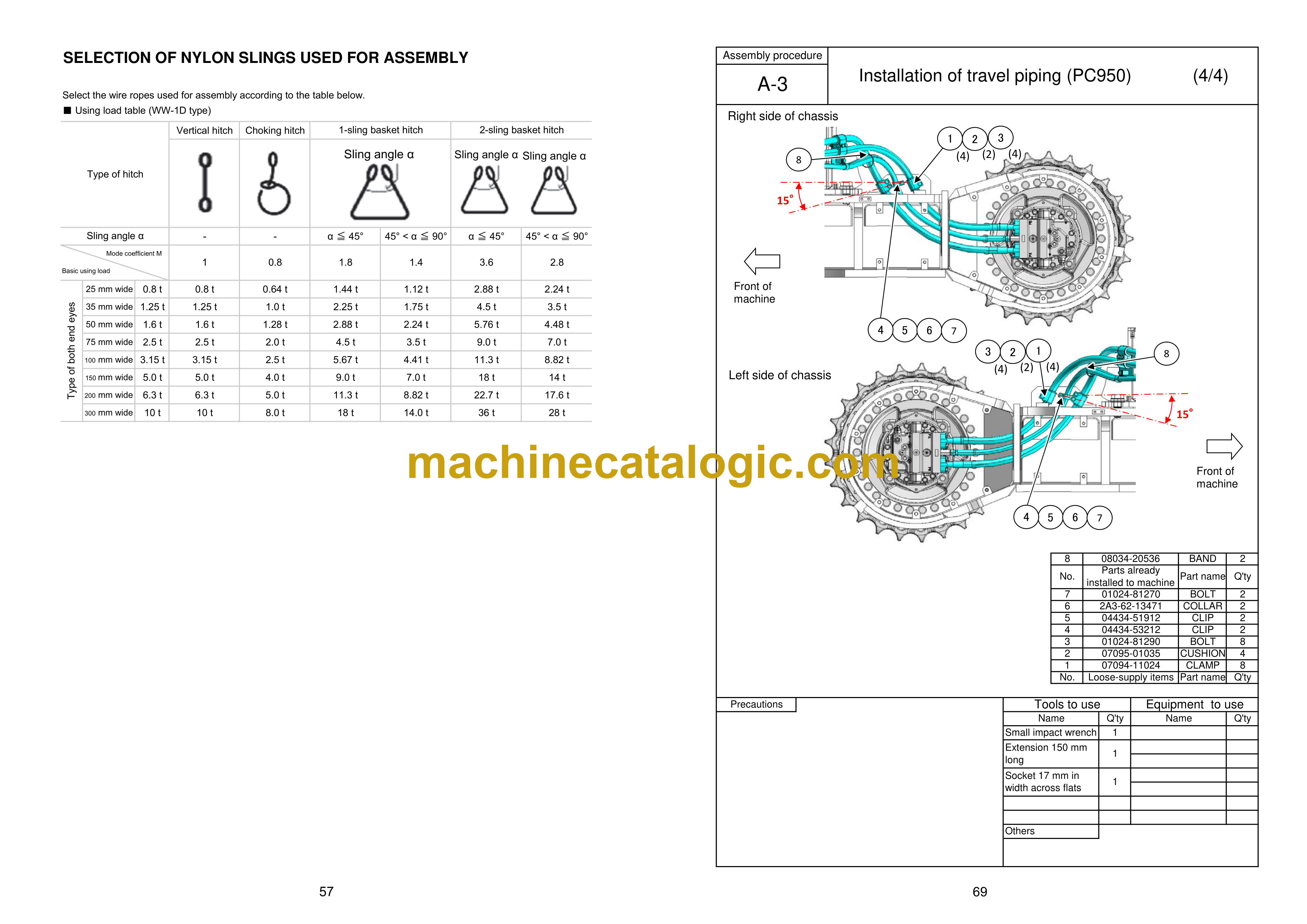
Selection of wire ropes used for assembly ………………………………………………………………………………. 56
Selection of nylon slings used for assembly ……………………………………………………………………………. 57
A. Assembly of chassis
A-1 Replacement of return filter (Standard → Flushing) …………………………………………………… 60
A-2 Installation of R.H. and L.H. track frames …………………………………………………………………. 63
A-3 Installation of travel piping (PC950) ………………………………………………………………………… 66
A-3 Installation of travel piping (PC950LC) …………………………………………………………………….. 70
A-4 Installation of step ………………………………………………………………………………………………… 74
A-5 Sticking revolving frame sheets ……………………………………………………………………………… 75
A-6 Installation of L.H. side step …………………………………………………………………………………… 76
A-7 Installation of R.H. side step ………………………………………………………………………………….. 77
A-8 Installation of handrail …………………………………………………………………………………………… 78
A-9 Installation of R.H. rearview mirror ………………………………………………………………………….. 84
A-10 Installation of L.H. rearview mirror ………………………………………………………………………….. 85
A-11 Sticking counterweight sheets ………………………………………………………………………………… 87
A-12 Assembly procedure of KomVision camera ………………………………………………………………. 88
A-13 Installation of counterweight revolving lamp (if equipped) …………………………………………… 94
A-14 Installation of counterweight rear lamp …………………………………………………………………….. 95
A-15 Installation of counterweight ………………………………………………………………………………….. 97
A-16 Installation of cab top step lamp …………………………………………………………………………….. 99
A-17 Installation of cab revolving lamp (if equipped) ……………………………………………………….. 101
A-18 Bleed air from hydraulic pump ……………………………………………………………………………… 103
A-19 Bleed air from travel motor …………………………………………………………………………………… 104
A-20 Installation of travel piping covers (PC950) …………………………………………………………….. 105
A-20 Installation of travel piping covers (PC950LC) ………………………………………………………… 108
A-21 Installation of track frame undercovers …………………………………………………………………… 111
A-22 Installation of travel motor guards …………………………………………………………………………. 112
A-23 Adjustment of track tension ………………………………………………………………………………….. 113
A-24 Installation of fire extinguisher (if equipped) ……………………………………………………………. 116
A-25 Installation of transportation jigs (muffler) ………………………………………………………………. 117
B. Assembly of work equipment
B-1 Release pressure remaining in hydraulic circuit ………………………………………………………. 120
B-2 Installation of boom anti-drop valve to boom cylinder ……………………………………………….. 122
B-3 Installation of boom cylinder to revolving frame ………………………………………………………. 124
B-4 Installation of boom anti-drop valve hoses ……………………………………………………………… 125
B-5 Installation of boom cylinder hoses ……………………………………………………………………….. 126
B-6 Bleed air from cylinder ………………………………………………………………………………………… 127
B-7 Installation of dust seal to boom foot ……………………………………………………………………… 128
B-8 Installation of arm dust seal …………………………………………………………………………………. 129
B-9 Installation of boom assembly ………………………………………………………………………………. 130
B-10 Installation of boom hoses (between machine and boom) …………………………………………. 132
B-11 Installation of arm anti-drop valve hoses (between machine and boom) ………………………. 133
B-12 Installation of boom cylinder ………………………………………………………………………………… 134
B-13 Fixing of boom anti-drop valve hoses …………………………………………………………………….. 135
B-14 Installation of arm assembly ………………………………………………………………………………… 136
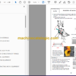
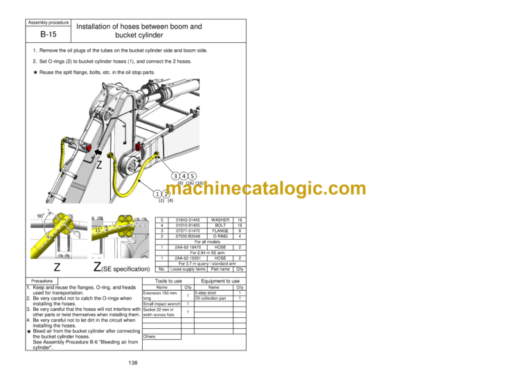
B-15 Installation of hoses between boom and bucket cylinder …………………………………………… 138
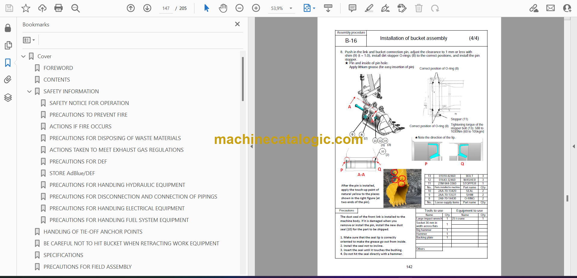
B-16 Installation of bucket assembly …………………………………………………………………………….. 139
B-17 Clearance standard for installation of work equipment ……………………………………………… 143
B-18 Installation of work equipment grease piping ………………………………………………………….. 144
B-19 Installation of work equipment lamp wiring ……………………………………………………………… 145
B-20 Greasing after assembling work equipment ……………………………………………………………. 146
M. Testing and maintenance procedures after completing assembly
M-1 Check hydraulic tank oil level and add oil ………………………………………………………………. 148
M-2 Flushing of hydraulic circuit ………………………………………………………………………………….. 150
M-3 Replacement of return filter (Flushing → Standard) …………………………………………………. 152
M-4 Check of oil and coolant levels at each section ……………………………………………………….. 154
M-5 Places to touch up after field assembly ………………………………………………………………….. 156
M-6 Setting of KomVision (Camera calibration) ……………………………………………………………… 157
M-7 Inspection method of 12 m visibility (KomVision) …………………………………………………….. 169
M-8 Check display of failure code ……………………………………………………………………………….. 171
M-9 Installation of fuel tank oil filler lock ………………………………………………………………………. 172


