Komatsu PW140-7, PW160-7, PW180-7, PW200-7 Hydraulic Excavator Operation and Maintenance Manual (VEAM410104)
These PW140-7 through PW200-7 wheeled excavators spend their days on roadwork, utility trenches, and tight urban jobs where you’re always moving between sites. This Operation and Maintenance Manual is what I’d keep handy to set up a solid service rhythm and keep the machine earning without surprise stoppages. When, for example, a driver reports sluggish swing and higher fuel burn after a week of trenching, I’d use this book to walk through the recommended checks, verify daily/weekly inspection points, and adjust operating habits before it turns into real downtime.
Applications & Use Cases
- Plan preventive maintenance so filters, joints, and wear points are inspected and serviced before they fail on the road.
- Set a realistic service schedule for multiple machines, aligning shop time with the manual’s guidance to avoid over- or under-servicing.
- Trace early hydraulic issues by following the suggested inspection order for leaks, overheating, or slow functions.
- Verify correct operating practices for travel, lifting, and attachment use to keep the upper structure and axles from premature wear.
- Train new operators on daily walk‑around checks and shutdown routines that match Komatsu’s recommendations.
FAQ
Q: Can I keep this manual on a tablet in the service truck?
A: Yes, it’s well-suited for digital use; you can zoom diagrams and use text search to jump to the checks you need on site.
Q: Is it worth printing sections of this manual?
A: Many shops print the routine maintenance pages and keep them in a binder by the time clock so techs can tick off inspections as they go.
Safety Note
Always follow the manual’s safety instructions and lockout procedures before inspecting, adjusting, or servicing any system on the machine.
📘 Show Index
Komatsu PW140-7, PW160-7, PW180-7, PW200-7 Hydraulic Excavator Index:
- 1. Foreword
- 1.1 Foreword
- 1.2 Safety information
- 1.2.1 Signal words
- 1.2.2 Safety labels
- 1.2.3 Emergency steering
- 1.2.4 Emergency braking
- 1.3 Introduction
- 1.3.1 Use of machine
- 1.3.2 Intended use
- 1.3.3 Directions of machine
- 1.3.4 Running in your new machine
- 1.4 Necessary information
- 1.4.1 Product Identification Number (PIN)/Machine serial no. plate and position
- 1.4.2 Engine serial no. plate and position
- 1.4.3 Position of service meter
- 1.4.4 Table to enter serial no. and distributor
- 1.5 Declaration of conformity (for machines placed on the market as from 29th December 2009)
- 1.6 Noise
- 1.6.1 Noise emission levels
- 1.6.2 Vibration levels
- 1.7 Contents
- 2. Safety
- 2.1 Safety labels
- 2.1.1 Location of safety labels
- 2.2 General precautions
- Understanding the machine
- 2.2.1 Precautions before starting operation
- 2.2.2 Preparations for safe operation
- 2.2.3 Fire prevention
- 2.2.4 Precautions when getting on or off machine
- 2.2.5 Do not get caught in articulated portion
- 2.2.6 Unauthorized modification
- 2.2.7 Precautions related to attachments and options
- 2.2.8 Precautions when running engine inside building
- 2.3 Precautions for operation
- 2.3.1 Precautions for jobsite
- 2.3.2 Starting engine
- 2.3.3 Operation
- 2.3.4 Transportation
- 2.3.5 Towing
- 2.3.6 Bucket with hook or bucket link with lifting eye
- 2.3.7 Handling of fluids
- 2.4 Precautions for maintenance
- 2.4.1 Precautions before starting inspection and maintenance
- 2.4.2 Precautions for inspection and maintenance
- 2.4.3 Tyres
- 2.5 Lifting capacity charts
- 2.5.1 Lifting capacity chart PW140-7
- 2.5.2 Lifting capacity chart PW160-7
- 2.5.3 Lifting capacity chart PW180-7
- 2.5.4 Lifting capacity chart PW200-7
- 2.5.5 Lifting capacity chart PW220-7
- 2.6 Overload caution
- 2.6.1 Overload caution
- 2.6.2 One piece boom – Overload caution PW140-7
- 2.6.3 Two piece boom – Overload caution PW140-7
- 2.6.4 One piece boom – Overload caution PW160-7
- 2.6.5 Two piece boom – Overload caution PW160-7
- 2.6.6 One piece boom – Overload caution PW180-7
- 2.6.7 Two piece boom – Overload caution PW180-7
- 2.6.8 Overload caution PW200-7
- 2.6.9 Overload caution PW220-7
- 3. Operation
- 3.1 General view
- 3.1.1 General view of machine
- 3.1.2 General view of controls and gauges
- 3.2 Explanation of components
- 3.2.1 Machine monitor
- 3.2.2 Basic operation of machine monitor
- 3.3 Basic check items
- 3.3.1 Caution items
- 3.3.2 Emergency stop items
- 3.3.3 Meter display portion
- 3.4 Switches
- 3.5 Control levers, pedals
- 3.6 Front window
- When opening
- When closing
- Removing front bottom window
- 3.7 Emergency exit from operator’s cab
- Ceiling window
- Clear rain visor
- Pull down sun visor
- Door lock
- 3.8 Cap, cover with lock
- 3.8.1 Method of opening and closing cap with lock (for the fuel tank filler port)
- 3.8.2 Method of opening and closing cover with lock (cover with lock)
- 3.9 Fuse
- 3.9.1 Fuse box 1
- 3.9.2 Fuse Box 2
- 3.10 Luggage tray
- 3.11 Ashtray
- 3.12 Cup holder
- 3.13 Hot and cool box
- 3.14 Cab radio
- 3.15 Power pick-up port
- 3.16 Handling air conditioner
- 3.16.1 General locations of control panel
- 3.16.2 Method of operation
- 3.16.3 Precautions when using air conditioner
- 3.16.4 Check, maintain machine equipped with air conditioner
- 3.16.5 Other functions
- 3.17 Fusible link
- 3.18 Controller
- 3.19 Tool box (chassis)
- 3.20 Refuelling pump
- 3.20.1 Safety
- 3.20.2 Procedure
- 3.20.3 Maintenance
- 3.21 Warning lamps
- 3.22 Handling accumulators
- 3.22.1 Control circuit accumulator (A)
- 3.22.2 Clutch control accumulator (B)
- 3.22.3 Brake circuit accumulators (C) ° 3
- 3.22.4 Brake circuit accumulators (C) ° 4
- 3.23 Operation
- 3.23.1 Check before starting engine
- 3.23.2 Check before starting
- 3.23.3 Adjustment of operator’s seat (air suspension seat)
- 3.23.4 Adjustment of operator’s seat (mechanical seat)
- 3.23.5 Seat belt
- 3.23.6 Rear view mirrors
- 3.23.7 Operations and checks before starting engine
- 3.23.8 Starting engine
- 3.23.9 Ambient temperature range for operation
- 3.23.10 Moving machine off
- 3.23.11 Steering
- 3.23.12 Travelling on public highway
- 3.23.13 Stopping and parking
- 3.23.14 Swinging (slewing the upper carriage)
- 3.23.15 Operation of work equipment
- 3.23.16 Working mode selection
- 3.23.17 Prohibitions for operation
- 3.23.18 Precautions for operation
- 3.23.19 Recommendations for travelling
- 3.23.20 Precautions when travelling up or down hills
- 3.23.21 How to escape from mud
- 3.23.22 Work possible using hydraulic excavator
- 3.23.23 Replacement and inversion of bucket
- 3.23.24 Stopping engine
- 3.23.25 Check after stopping engine
- 3.24 Transportation
- 3.24.1 Transportation procedure
- 3.24.2 Loading, unloading work
- 3.24.3 Securing machine
- 3.24.4 Unloading
- 3.24.5 How to lift the machine
- 3.24.6 Precautions for transportation
- 3.24.7 Travelling posture
- 3.25 Cold weather operation
- 3.25.1 Precautions for low temperature
- 3.25.2 Precautions after completion of work
- 3.25.3 After cold weather
- 3.26 Long-term storage
- 3.26.1 Before storage
- 3.26.2 During storage
- 3.26.3 After storage
- 3.26.4 Starting machine after long-term storage
- 3.27 Troubleshooting
- 3.27.1 Phenomena that are not failures
- 3.28 Method of towing machine
- 3.29 Precautions on particular jobsites
- 3.30 Discharged battery
- 3.30.1 Removal and installation of battery
- 3.30.2 Battery charges
- 3.30.3 Starting engine with booster cables
- 3.31 Other trouble
- 3.31.1 Electrical system
- 3.31.2 Chassis
- 3.31.3 Engine
- 3.31.4 Electronic control system
- 4. Maintenance
- 4.1 Guides to maintenance
- 4.2 Outline of service
- 4.2.1 Outline of oil, fuel, coolant
- 4.2.2 Outline of electric system
- 4.2.3 Outline of hydraulic system
- 4.3 Wear parts list
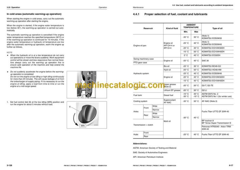
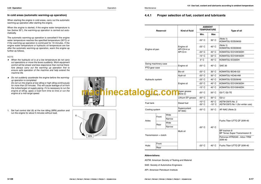
- 4.4 Use fuel, coolant and lubricants according to ambient temperature
- 4.4.1 Proper selection of fuel, coolant and lubricants
- 4.5 Recommended brands, recommended quality for products other than KOMATSU genuine oil
- 4.6 Standard tightening torques for bolts and nuts
- 4.6.1 Introduction of necessary tools
- 4.6.2 Tightening torque specifications
- 4.7 Periodic replacement of safety critical parts
- 4.7.1 Safety critical parts
- 4.8 Maintenance schedule chart
- 4.9 Key to lubrication points
- 4.10 Maintenance interval for hydraulic breaker
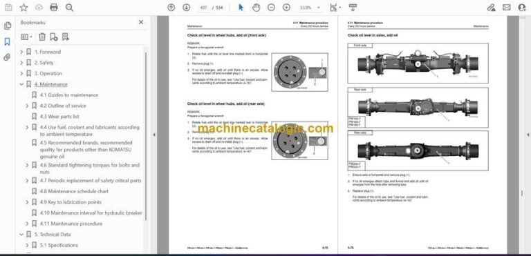
- 4.11 Maintenance procedure
- 4.11.1 Initial 50 hours maintenance (only after the first 50 hours)
- 4.11.2 Initial 250 hours maintenance (only after the first 250 hours)
- 4.11.3 Initial 500 hours maintenance (only after the first 500 hours)
- 4.11.4 When required
- 4.11.5 Check before starting
- 4.11.6 Every 50 hours service
- 4.11.7 Every 100 hours service
- 4.11.8 Every 250 hours service
- 4.11.9 Every 500 hours service
- 4.11.10 Every 1000 hours service
- 4.11.11 Every 2000 hours service
- 4.11.12 Every 4000 hours service
- 4.11.13 Every 5000 hours service
- 5. Technical Data
- 5.1 Specifications
- Operating weight
- 5.1.1 Dimensions
- 5.1.2 Working range – One piece boom
- 5.1.3 Working range – Two piece boom
- 5.1.4 Working range – Rotating arm
- 6. Attachments, Options
- 6.1 General precautions for safety
- 6.1.1 Precautions when selecting
- 6.1.2 Read the instruction manual thoroughly
- 6.1.3 Precautions when removing or installing
- 6.1.4 Precautions when using
- 6.2 Hydraulic quick coupler piping
- 6.2.1 Locations
- 6.2.2 Operation
- 6.3 Handling bucket with hook
- 6.3.1 Checking for damage to bucket with hook
- 6.3.2 Prohibited operations
- 6.3.3 Precautions during operations
- 6.4 Machines ready for attachments
- 6.4.1 Clamshell operation selector valves
- 6.4.2 Handling the clamshell bucket
- 6.4.3 Hydraulic circuit
- 6.4.4 Operation
- 6.4.5 Method for releasing pressure in control circuit of machines equipped with accumulator
- 6.4.6 Long-term storage
- 6.4.7 Specifications
- 6.5 Introduction of attachments and extending machine service life
- 6.5.1 Hydraulic breaker
- 6.5.2 Power ripper
- 6.5.3 Fork grab
- 6.5.4 Grapple bucket
- 6.5.5 Scrap grapple
- 6.5.6 Crusher and smasher
- 6.5.7 Hydraulic pile driver
- 6.5.8 Hydraulic excavator with multipurpose crane
- 6.6 Rotating arm
- 6.6.1 General location and specifications.
- 6.6.2 Maintenance requirement
- 6.6.3 General view of controls
- 6.6.4 Excavator’s work
- 6.6.5 Replacement of bucket
- 6.7 Handling machines equipped with KOMTRAX
- 6.8 Central lubrication system
- 6.8.1 Operating the central lubrication system
- 6.8.2 Display and control unit
- 6.8.3 Changing the lubrication interval times
- 6.9 Cleanfix fan
- 7. Index
- 8. Notes
Komatsu

