The Komatsu SK715-8E0 Skid Steer Loader is a compact loader used for tight job sites, material handling, light excavation, and site cleanup. People who usually reach for the Komatsu SK715-8E0 Skid Steer Loader Shop Manual (WENBM00580) are shop mechanics, field techs, and serious owners who do their own repairs. They’re trying to fix hydraulic or electrical faults, rebuild components correctly, and avoid repeat failures. Think “workshop-level repair guide,” not a quick operator booklet.
What this manual helps you do
- Trace hydraulic issues from the control levers through hoses, valves, and pumps so you’re not just guessing at failed parts.
- Diagnose electrical faults using wiring diagrams and step‑by‑step test sequences with a meter.
- Follow teardown and reassembly procedures for major components like the drive system, loader arms, and attachments.
- Check adjustment points on linkages, controls, and safety systems so the machine operates smoothly and safely.
- Verify proper service procedures after repairs, including bleed steps, function checks, and common post-repair mistakes students often make.
Who this is for
This is aimed at field technicians, shop mechanics, and advanced trainees who need workshop procedures for the SK715-8E0. If you just want basic operation or daily maintenance, you’d be better off with the Operation and Maintenance Manual instead of this shop manual.
FAQ
Q: Is this a PDF I can search and print?
A: Yes, it’s typically provided as a searchable PDF that you can view on a device or print pages for the bench.
Q: Does it go deep enough for full overhauls?
A: Yes, this kind of shop manual usually covers diagnostic flows, disassembly/reassembly, and adjustment procedures for workshop-level repairs.
Q: How do I know it matches my exact SK715-8E0 machine?
A: The manual is written for the SK715-8E0 model; you should still confirm your machine ID plate matches this model before relying on it.
Bottom line: If you’re repairing or teaching how to repair the Komatsu SK715-8E0, this shop manual is what you want; if you’re just operating it, keep looking for the operator’s or maintenance manual instead.
📘 Show Index
Table of Contents:
- 00 Index and Foreword
- Index
- Foreword, Safety, Basic Information
- How to Read the Shop Manual
- Safety Notice for Operation
- Precautions to Prevent Fire
- Procedures If Fire Occurs
- Precautions When You Dispose of Waste Materials
- Precautions When You Handle Hydraulic Equipment
- Precautions When You Disconnect and Connect Pipings
- Precautions When You Handle Electrical Equipment
- Precautions When You Handle Fuel System Equipment
- Precautions When You Handle Intake System Equipment
- Practical Use of KOMTRAX
- Disconnect and Connect Push-Pull Type Coupler
- How to Disconnect and Connect Type 1 Push-Pull Type Coupler
- How to Disconnect and Connect Type 2 Push-Pull Type Coupler
- How to Disconnect and Connect Type 3 Push-Pull Type Coupler
- Precautions for Disconnection and Connection of Connectors
- How to Disconnect and Connect Deutsch Connector
- How to Disconnect and Connect Slide Lock Type Connector
- How to Disconnect and Connect Connector with Lock to Pull
- How to Disconnect and Connect Connector with Lock to Push
- How to Disconnect and Connect Connector with Housing to Rotate
- Standard Tightening Torque Table
- Conversion Table
- Abbreviation List
- 01 Specifications
- Table of Contents
- Specifications
- Specification Drawing
- Specification
- Weight Table
- Fuel, Coolant and Lubricants by Ambient Temperature
- 10 Structure and Function
- Table of Contents
- NOx Control System
- Function of NOx Control System
- Boot-up System
- Layout Drawing of Boot-up System
- System Operating Lamp System
- System Diagram of System Operating Lamp System
- Function of Operation Lamp System
- Quick Release Battery Terminal (-)
- Function of Quick Release Battery Terminal (-)
- Engine System
- Layout Drawing of Engine System
- Engine Control System
- System Diagram of Engine Control
- Function of Engine Control System
- Component Parts of Engine System
- Cooling System
- Layout Drawing of Cooling System
- Control System
- Layout Drawing of Control System
- Machine Monitor System
- System Diagram of Machine Monitor System
- KOMTRAX System
- System Diagram of KOMTRAX System
- Function of KOMTRAX System
- Component Parts of Control System
- Machine Monitor
- KOMTRAX Terminal
- Machine Controller
- Hydraulic System
- Layout Drawing of Hydraulic System
- CLSS
- Structure of CLSS
- Function of CLSS
- Component Parts of Hydraulic System
- Hydraulic Tank
- Hydraulic Pump
- Control Valve
- Work Equipment System
- Layout Drawing of Work Equipment System
- PPC Lock System
- System Diagram of PPC Lock
- Function of PPC Lock System
- Component Parts of Work Equipment System
- Work Equipment PPC Valve
- Attachment PPC Valve
- Solenoid Valve Group
- Super Flow Solenoid Valve
- Pilot Circuit Accumulator
- Travel System
- Layout Drawing of Travel System
- System Diagram of Travel Control System
- Function of Travel Control System
- Component Parts of Travel System
- Travel PPC Valve
- Final Drive
- Power Train
- Transmission
- Work Equipment
- Structure of Work Equipment
- Function of Work Equipment
- Work Equipment Clearance Adjustment Shim
- Function of Work Equipment Clearance Adjustment Shim
- 20 Standard Value Table
- Table of Contents
- Standard Value Table for Engine
- Standard Value Table for Machine
- Machine Posture and Procedures to Measure Performance
- 30 Testing and Adjusting
- Table of Contents
- Engine and Cooling System
- Examine Engine Speed
- How to Examine Engine High Idle Speed
- How to Examine Engine Low Idle Speed
- How to Examine Engine at Travel Relief
- How to Examine Engine at Travel and Work Equipment Relief
- Examine Exhaust Gas Color
- How to Examine Exhaust Gas Color with the Handy Smoke Checker
- How to Examine Exhaust Gas Color with Smoke Meter
- Examine and Adjust Valve Clearance
- How to Examine Valve Clearance
- How to Adjust Valve Clearance
- Examine Compression Pressure
- How to Examine Compression Pressure
- Examine Engine Oil Pressure
- How to Examine Engine Oil Pressure
- Bleed Air from Fuel System
- How to Bleed Air from Fuel System
- Examine Fuel Circuit for Leakage
- How to Examine Fuel Circuit for Leakage at Engine Stop
- How to Examine Fuel Circuit for Leakage at Engine Low Idle
- How to Examine Fuel Circuit for Leakage at Engine High Idle
- Handle Cylinder Cut-out Mode Operation
- Examine and Adjust Alternator Belt Tension
- How to Examine Alternator Belt Tension
- How to Adjust Alternator Belt Tension
- Frame
- Examine and Adjust Gear Chain Tension
- How to Examine Gear Chain Tension
- How to Adjust Gear Chain Tension
- Hydraulic System
- Release Remained Pressure in Hydraulic Circuit
- How to Release Remained Pressure from Hydraulic Tank
- How to Release Remained Pressure in PPC Accumulator Circuit
- How to Release Remained Pressure in Hydraulic Cylinder Circuit
- Examine Oil Pressure of Work Equipment
- How to Examine Unload Pressure
- How to Examine Oil Pressure of Work Equipment
- Adjust Oil Pressure of Work Equipment
- How to Adjust Unload Pressure
- How to Adjust Oil Pressure of Work Equipment Relief Pressure
- Examine Oil Pressure of Control Circuit
- How to Examine Oil Pressure of Control Circuit
- Examine and Adjust Oil Pressure of Pump Circuit
- How to Examine Oil Pressure of Travel Pump HST Charge Circuit
- How to Adjust Oil Pressure of Travel Pump HST Charge Circuit
- How to Examine Oil Pressure of Travel Pump AS Valve
- How to Adjust Oil Pressure of Travel Pump AS Valve at Low Idling
- How to Adjust Oil Pressure of Travel Pump AS Valve at High Idling
- Examine Outlet Pressure of Solenoid Valve
- How to Examine Outlet Pressure of Solenoid Valve
- Operating Condition of Solenoid Valve
- Examine PPC Valve Outlet Pressure
- How to Examine Outlet Pressure of PPC Valve
- How to Examine Outlet Pressure of PPC Valve for Travel System
- Examine Parking Brake Release Pressure
- How to Examine Parking Brake Release Pressure
- Examine and Adjust Travel Deviation
- How to Examine Travel Deviation at High Idling
- How to Examine Travel Deviation at Medium Idling
- How to Adjust Travel Deviation
- Adjust Play of Work Equipment and Travel PPC Valves
- How to Adjust Play of Work Equipment and Travel PPC Valves
- Examine Parts Which Cause Hydraulic Drift of Work Equipment
- How to Examine Parts Which Cause Hydraulic Drift of Arm Cylinder and Bucket Cylinder
- How to Examine Parts that Cause Hydraulic Drift of PPC Valve
- Bleed Air from Hydraulic System
- How to Bleed Air from Travel Pump
- How to Bleed Air from Cylinder
- Pressurize Hydraulic Tank
- How to Pressurize Hydraulic Tank
- Electrical System
- How to Set and Operate Machine Monitor
- Operator Mode
- Examine Function by LCD (Liquid Crystal Display)
- Examine Function of Service Meter
- Usage Limitation and Maintenance Password Change Function
- Service Mode
- How to Start Up KOMTRAX Terminal
- Handle Voltage Circuit of Engine Controller
- 40 Troubleshooting
- Table of Contents
- Abbreviation List
- Related Information to Troubleshooting
- General Troubleshooting Points
- Sequence of Events in Troubleshooting
- Troubleshooting Points for Aftertreatment System
- Checks Before Troubleshooting
- Inspection Procedure Before Troubleshooting
- Test in Accordance with Testing Procedure
- Examine Fuel Level, Add Fuel
- Examine Water Separator, Drain Water and Sediment
- Replace Fuel Prefilter Element
- Replace Fuel Main Filter Cartridge
- Examine Oil Level in Engine Oil Pan, Add Oil
- Replace Oil in Engine Oil Pan and Engine Oil Filter Cartridge
- Examine Coolant Level, Add Coolant
- Examine Clogging of Air Cleaner
- Examine Oil Level in Hydraulic Tank, Add Oil
- Replace Hydraulic Oil Drain Filter
- Examine Gear Chains Tension
- Examine Oil Level in Final Transmission
- Bleed Air from Fuel System
- Bleed Air from Hydraulic System
- Examine Electric Equipment
- Procedure for Troubleshooting
- Information Shown in Troubleshooting Table
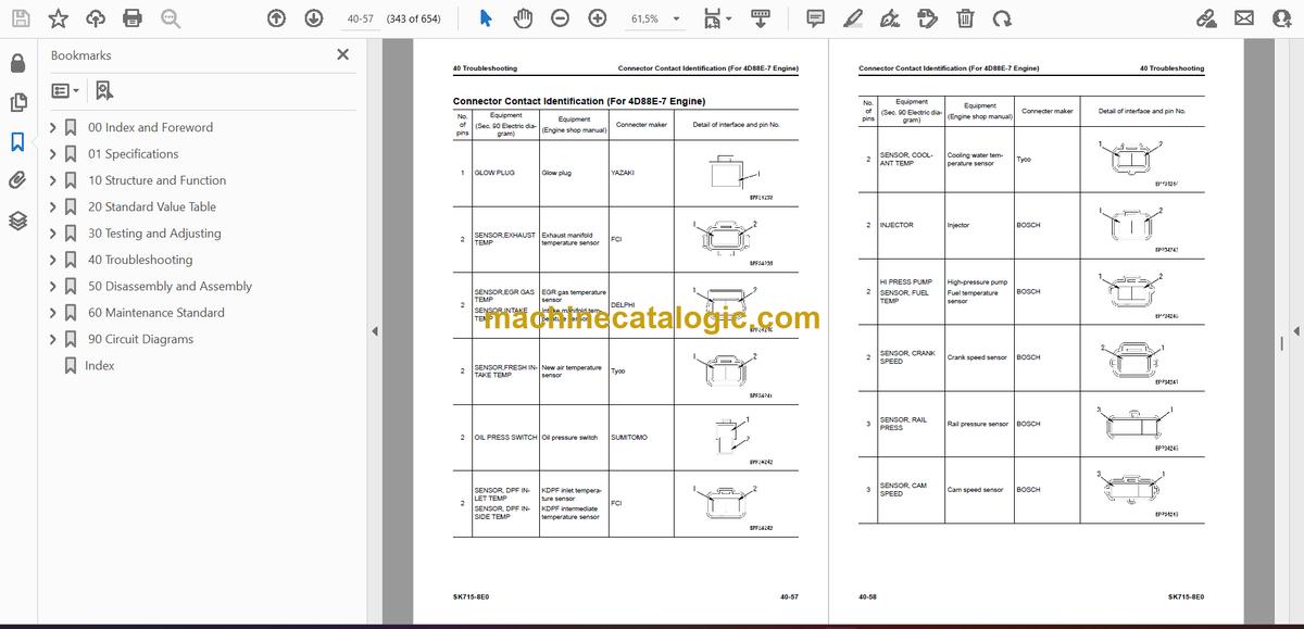
- Connector Contact Identification (For 4D88E-7 Engine)
- T-Branch Box and T-Branch Adapter Table
- Fuse Location Table
- Failure Code Table
- Troubleshooting by Failure Code (Display of Code)
- Failure Code [989L00]
- Failure Code [989M00]
- Failure Code [989N00]
- Failure Code [AQ20R1]
- Failure Code [AS00R2]
- Failure Code [AS00R3]
- Failure Code [AS00R4]
- Failure Code [B@BCNS]
- Failure Code [D19JKZ]
- Failure Code [D811MC]
- Failure Code [D862KA]
- Failure Code [D8ALKA]
- Failure Code [D8ALKB]
- Failure Code [D8AQKR]
- Failure Code [DAF0KT]
- Failure Code [DAF0MB]
- Failure Code [DAF0MC]
- Failure Code [DAF3KK]
- Failure Code [DAFGMC]
- Failure Code [DAFLKA]
- Failure Code [DAFLKB]
- Failure Code [DAFQKR]
- Failure Code [DB2QKR]
- Failure Code [DBH0MC]
- Failure Code [DBH2KK]
- Failure Code [DBHLKA]
- Failure Code [DBHLKB]
- Failure Code [DBHQKR]
- Failure Code [F@HSZG]
- Failure Code [F@HSZL]
- Troubleshooting of Electrical System (E-Mode)
- Engine Does Not Start (Engine Does Not Crank)
- Engine Does Not Start (Fuel Feed Pump System)
- Automatic Preheating System Does Not Operate
- When Starting Switch is Turned to ON Position, Machine Monitor Displays Nothing
- Engine Coolant Temperature Monitor Comes On in White While Engine Runs
- Charge Level Monitor Comes On in Red While Engine is in Operation
- Fuel Level Monitor Comes On in Red While Engine Runs
- Engine Coolant Temperature Monitor Comes On in Red While Engine is in Operation
- Engine Oil Pressure Monitor Comes on in Red While Engine is in Operation
- Fuel Gauge Display Does Not Move from Minimum or Maximum
- Display of Fuel Gauge is Different from Actual Fuel Level
- Coolant Temperature Gauge Display Does Not Move from Minimum or Maximum
- Display of Coolant Temperature Gauge is Different from Actual Coolant Temperature
- Some Areas of Machine Monitor Screen are Not Shown
- Function Switch Does Not Operate
- Alarm Buzzer Does Not Sound
- Alarm Buzzer Cannot be Canceled
- Service Meter is Not Shown, While Starting Switch is in OFF Position
- Service Mode Cannot be Selected
- Alarm Does Not Sound During Travel
- Travel Alarm Does Not Stop When Machine Stops
- Horn Does Not Sound
- Horn Does Not Stop
- Front or Rear Working Lamps Do Not Light Up
- When Front Wiper Switch is Operated, Front Wiper Does Not Operate
- When Rear Wiper Switch is Operated, Rear Wiper Does Not Operate
- When Front Wiper Switch is Operated, Front Window Washer Does Not Operate
- When Rear Wiper Switch is Operated, Rear Window Washer Does Not Operate
- Travel Indicator is Not Shown Correctly with Monitoring Function
- Arm IN is Not Shown Normally in Monitoring Function
- KOMTRAX System Does Not Operate Normally
- Troubleshooting for Hydraulic and Mechanical Systems (H Mode)
- Information Shown in Troubleshooting Table (H-Mode)
- Travel Does Not Operate (One or All Directions)
- Travel Speed is Low
- Work Equipment Does Not Operate
- Work Equipment Speed is Low
- Work Equipment Fine Control Performance or Response is Poor
- Unusual Noise Heard from Hydraulic Pump
- Troubleshooting of Engine (S-Mode)
- Information Shown in Troubleshooting Table (S-Mode)
- S-1 Engine Does Not Crank When Starting Switch is Turned to Start Position
- S-2 Engine Cranks but No Exhaust Smoke Comes Out
- S-3 Fuel is Injected but Engine Does Not Start (Misfiring: Engine Cranks but Does Not Start)
- S-4 Engine Startability is Unsatisfactory
- S-5 Engine Does Not Pick Up Smoothly
- S-6 Engine Stops During Operation
- S-7 Engine Runs Rough or is Not Stable
- S-8 Engine Lacks Power
- S-9 KDPF Becomes Clogged in a Short Time
- S-10 Engine Oil Consumption is Excessive
- S-11 Oil Becomes Dirty Quickly
- S-12 Fuel Consumption is Excessive
- S-13 Oil is in Coolant (or Coolant Spurts Back or Coolant Level goes Down)
- S-14 Oil Pressure Drops
- S-15 Fuel Mixes Into Engine Oil
- S-16 Water Mixes Into Engine Oil (Milky)
- S-17 Coolant Temperature Increases Too High (Overheating)
- S-18 Unusual Noise is Heard
- S-19 Vibration is Excessive
- S-20 Air Cannot be Bled from Fuel Circuit
- 50 Disassembly and Assembly
- Table of Contents
- Related Information on Disassembly and Assembly
- Read This Manual
- Coating Materials List
- Engine and Cooling System
- Remove and Install Starter Assembly
- How to Remove Starter Assembly
- How to Install Starter Assembly
- Remove and Install Radiator Assembly
- How to Remove Radiator Assembly
- How to Install Radiator Assembly
- Remove and Install Engine and Pump Assembly
- How to Remove Engine and Pump Assembly
- How to Install Engine and Pump Assembly
- Remove and Install Fuel Tank Assembly
- How to Remove Fuel Tank Assembly
- How to Install Fuel Tank Assembly
- Remove and Install Alternator Assembly
- How to Remove Alternator Assembly
- How to Install Alternator Assembly
- Remove and Install Air Cleaner Assembly
- How to Remove Air Cleaner Assembly
- How to Install Air Cleaner Assembly
- Frame
- Remove and Install Engine Hood
- How to Remove Engine Hood
- How to Install Engine Hood
- Remove and Install Heater Assembly
- How to Remove Heater Assembly
- How to Install Heater Assembly
- Raise Arm and Tilt Cab
- How to Raise Arm
- How to Tilt Cab
- Fully Tilt and Rest the Cab Assembly
- How to Tilt of Cab
- How to Rest of Cab
- Remove and Install Cab Assembly
- How to Remove Cab Assembly
- How to Install Cab Assembly
- Remove and Install Wheel Hub Assembly
- How to Remove Wheel Hub Assembly
- How to Install Wheel Hub Assembly
- Remove and Install Travel Motor Assembly
- How to Remove Travel Motor Assembly
- How to Install Travel Motor Assembly
- Hydraulic System
- Remove and Install Pump Assembly
- How to Remove Pump Assembly
- How to Install Pump Assembly
- Remove and Install Gear Pump Assembly
- How to Remove Gear Pump Assembly
- How to Install Gear Pump Assembly
- Remove and Install Pump Coupling
- How to Remove Pump Coupling
- How to Install Pump Coupling
- Remove and Install Control Valve
- How to Remove Control Valve
- How to Install Control Valve
- Remove and Install PPC Valve
- How to Remove PPC Valve
- How to Install PPC Valve
- Work Equipment
- Remove and Install Arm
- How to Remove Arm
- How to Install Arm
- Remove and Install Lift Cylinder
- How to Remove Lift Cylinder
- How to Install Lift Cylinder
- Remove and Install Bucket Cylinder
- How to Remove Bucket Cylinder
- How to Install Bucket Cylinder
- Remove and Install Equipment Support Frame
- How to Remove Equipment Support Frame
- How to Install Equipment Support Frame
- Electrical System
- Remove and Install Battery
- How to Remove Battery
- How to Install Battery
- 60 Maintenance Standard
- Table of Contents
- Engine and Cooling System
- Maintenance Standard for PTO
- Hydraulic System
- Maintenance Standard for Control Valve (Standard Flow)
- Maintenance Standard for Control Valve (Super Flow)
- Maintenance Standard for Work Equipment PPC Valve
- Maintenance Standard for Travel PPC Valve
- Maintenance Standard for Attachment PPC Valve
- Power Train
- Maintenance Standard for Transmission
- Work Equipment
- Maintenance Standard for Work Equipment Linkage
- Maintenance Standard for Lift Cylinder
- Maintenance Standard for Tilt Cylinder
- 90 Circuit Diagrams
- Table of Contents
- Read the Codes for Electric Cable
- Hydraulic Circuit Diagram
- Symbols Used in Hydraulic Circuit Diagram
- Hydraulic Circuit Diagram
- Electrical Circuit Diagram
- Symbols Used in Electric Circuit Diagram
- Electrical Circuit Diagram (1/6)
- Electrical Circuit Diagram (2/6)
- Electrical Circuit Diagram (3/6)
- Electrical Circuit Diagram (4/6)
- Electrical Circuit Diagram (5/6)
- Electrical Circuit Diagram (6/6)
- Index
Komatsu


