The Komatsu SK820-8E0 Skid Steer Loader is a compact loader that spends its life loading trucks, handling pallets, and doing tight-site work where downtime hurts fast. People who reach for the Komatsu SK820-8E0 Skid Steer Loader Shop Manual (WENBM00590) are usually shop mechanics, dealer-level techs, or fleet managers backing them up. They’re trying to plan real repairs, not guesswork—things like engine work, hydraulic faults, or drive issues that take a machine out of service. If you’re trying to standardize repairs across a small fleet, this is the kind of document you build your procedures around.
What this manual helps you do
- Trace hydraulic problems in the loader’s working circuits using diagrams and step-by-step diagnostic routines.
- Check and adjust engine, drive, and brake systems the way a workshop would, so repairs are repeatable and safe.
- Follow disassembly and reassembly sequences for major components, with the kind of notes techs need to avoid rework.
- Diagnose electrical issues with wiring information that lets you track down shorts, opens, and sensor faults.
- Handle scheduled heavy services and mid-life overhauls with the same workflow most dealer shops use.
Who this is for
This shop manual suits field techs, shop mechanics, and fleet managers who plan and control workshop-level repairs. It’s not the right buy if you only need daily checks or basic operation; in that case you’d want the Operation and Maintenance manual instead.
FAQ
Q: Is this a searchable PDF I can print from?
A: Yes, it’s a PDF you can search on-screen and print pages or sections for the shop as needed.
Q: Does it go deep enough for full tear-downs?
A: Yes, the Komatsu SK820-8E0 Skid Steer Loader Shop Manual walks through diagnostic procedures, disassembly sequences, and workshop adjustment references used during major repairs.
Q: How do I know it matches my exact SK820-8E0 machine?
A: This manual targets the SK820-8E0 variant; as with any shop manual, you’ll want to confirm your machine’s ID plate and options match the SK820-8E0 designation before relying on it.
Bottom line: if you’re responsible for keeping SK820-8E0 loaders running and you do your own repairs, this is the right manual; if you only outsource work and just need operating guidance, you can skip it.
📘 Show Index
Table of Contents:
- 00 Index and Foreword
- Index
- Foreword, Safety, Basic Information
- How to Read the Shop Manual
- Safety Notice for Operation
- Precautions to Prevent Fire
- Procedures If Fire Occurs
- Precautions When You Dispose of Waste Materials
- Precautions When You Handle Hydraulic Equipment
- Precautions When You Disconnect and Connect Pipings
- Precautions When You Handle Electrical Equipment
- Precautions When You Handle Fuel System Equipment
- Precautions When You Handle Intake System Equipment
- Practical Use of KOMTRAX
- Disconnect and Connect Push-Pull Type Coupler
- How to Disconnect and Connect Type 1 Push-Pull Type Coupler
- How to Disconnect and Connect Type 2 Push-Pull Type Coupler
- How to Disconnect and Connect Type 3 Push-Pull Type Coupler
- Precautions for Disconnection and Connection of Connectors
- How to Disconnect and Connect Deutsch Connector
- How to Disconnect and Connect Slide Lock Type Connector
- How to Disconnect and Connect Connector with Lock to Pull
- How to Disconnect and Connect Connector with Lock to Push
- How to Disconnect and Connect Connector with Housing to Rotate
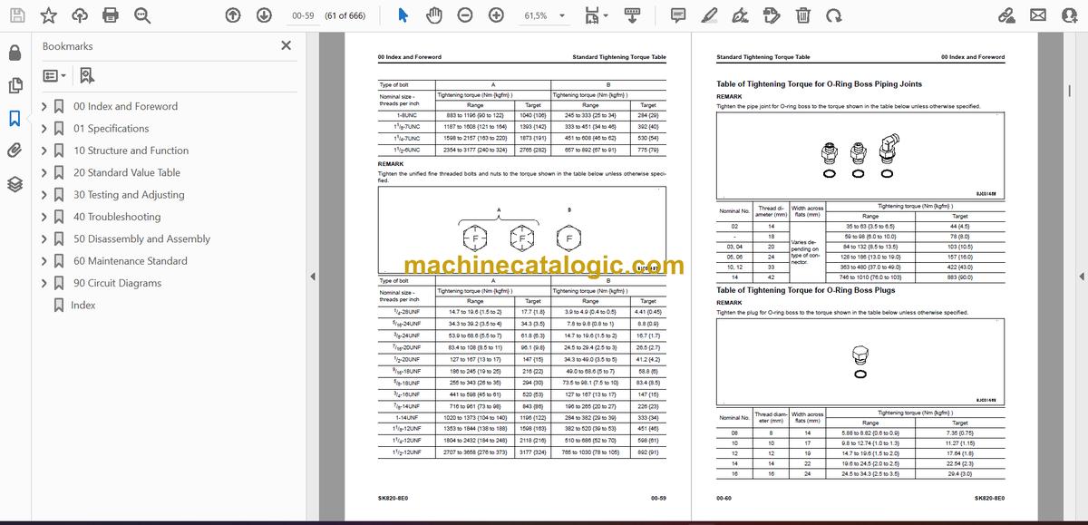
- Standard Tightening Torque Table
- Conversion Table
- Abbreviation List
- 01 Specifications
- Table of Contents
- Specifications
- Specification Drawing
- Specification
- Weight Table
- Fuel, Coolant and Lubricants by Ambient Temperature
- 10 Structure and Function
- Table of Contents
- NOx Control System
- Function of NOx Control System
- Boot-up System
- Layout Drawing of Boot-up System
- System Operating Lamp System
- System Diagram of System Operating Lamp System
- Function of Operation Lamp System
- Quick Release Battery Terminal (-)
- Function of Quick Release Battery Terminal (-)
- Engine System
- Layout Drawing of Engine System
- Engine Control System
- System Diagram of Engine Control
- Function of Engine Control System
- Component Parts of Engine System
- Cooling System
- Layout Drawing of Cooling System
- Control System
- Layout Drawing of Control System
- Machine Monitor System
- System Diagram of Machine Monitor System
- KOMTRAX System
- System Diagram of KOMTRAX System
- Function of KOMTRAX System
- Component Parts of Control System
- Machine Monitor
- KOMTRAX Terminal
- Machine Controller
- Hydraulic System
- Layout Drawing of Hydraulic System
- CLSS
- Structure of CLSS
- Function of CLSS
- Component Parts of Hydraulic System
- Hydraulic Tank
- Hydraulic Pump
- Control Valve
- Work Equipment System
- Layout Drawing of Work Equipment System
- PPC Lock System
- System Diagram of PPC Lock
- Function of PPC Lock System
- Component Parts of Work Equipment System
- Work Equipment PPC Valve
- Attachment PPC Valve
- Solenoid Valve Group
- Super Flow Solenoid Valve
- Pilot Circuit Accumulator
- Travel System
- Layout Drawing of Travel System
- System Diagram of Travel Control System
- Function of Travel Control System
- Component Parts of Travel System
- Travel PPC Valve
- Final Drive
- Power Train
- Transmission
- Work Equipment
- Structure of Work Equipment
- Function of Work Equipment
- Work Equipment Clearance Adjustment Shim
- Function of Work Equipment Clearance Adjustment Shim
- 20 Standard Value Table
- Table of Contents
- Standard Value Table for Engine
- Standard Value Table for Machine
- Machine Posture and Procedures to Measure Performance
- 30 Testing and Adjusting
- Table of Contents
- Engine and Cooling System
- Examine Engine Speed
- How to Examine Engine High Idle Speed
- How to Examine Engine Low Idle Speed
- How to Examine Engine at Travel Relief
- How to Examine Engine at Travel and Work Equipment Relief
- Examine Exhaust Gas Color
- How to Examine Exhaust Gas Color with the Handy Smoke Checker
- How to Examine Exhaust Gas Color with Smoke Meter
- Examine and Adjust Valve Clearance
- How to Examine Valve Clearance
- How to Adjust Valve Clearance
- Examine Compression Pressure
- How to Examine Compression Pressure
- Examine Engine Oil Pressure
- How to Examine Engine Oil Pressure
- Bleed Air from Fuel System
- How to Bleed Air from Fuel System
- Examine Fuel Circuit for Leakage
- How to Examine Fuel Circuit for Leakage at Engine Stop
- How to Examine Fuel Circuit for Leakage at Engine Low Idle
- How to Examine Fuel Circuit for Leakage at Engine High Idle
- Handle Cylinder Cut-out Mode Operation
- Examine and Adjust Alternator Belt Tension
- How to Examine Alternator Belt Tension
- How to Adjust Alternator Belt Tension
- Frame
- Examine and Adjust Gear Chain Tension
- How to Examine Gear Chain Tension
- How to Adjust Gear Chain Tension
- Hydraulic System
- Release Remained Pressure in Hydraulic Circuit
- How to Release Remained Pressure from Hydraulic Tank
- How to Release Remained Pressure in PPC Accumulator Circuit
- How to Release Remained Pressure in Hydraulic Cylinder Circuit
- Examine Oil Pressure of Work Equipment
- How to Examine Unload Pressure
- How to Examine Oil Pressure of Work Equipment
- Adjust Oil Pressure of Work Equipment
- How to Adjust Unload Pressure
- How to Adjust Oil Pressure of Work Equipment Relief Pressure
- Examine Oil Pressure of Control Circuit
- How to Examine Oil Pressure of Control Circuit
- Examine and Adjust Oil Pressure of Pump Circuit
- How to Examine Oil Pressure of Travel Pump HST Charge Circuit
- How to Adjust Oil Pressure of Travel Pump HST Charge Circuit
- How to Examine Oil Pressure of Travel Pump AS Valve
- How to Adjust Oil Pressure of Travel Pump AS Valve at Low Idling
- How to Adjust Oil Pressure of Travel Pump AS Valve at High Idling
- Examine Outlet Pressure of Solenoid Valve
- How to Examine Outlet Pressure of Solenoid Valve
- Operating Condition of Solenoid Valve
- Examine PPC Valve Outlet Pressure
- How to Examine Outlet Pressure of PPC Valve
- How to Examine Outlet Pressure of PPC Valve for Travel System
- Examine Parking Brake Release Pressure
- How to Examine Parking Brake Release Pressure
- Examine and Adjust Travel Deviation
- How to Examine Travel Deviation at High Idling
- How to Examine Travel Deviation at Medium Idling
- How to Adjust Travel Deviation
- Adjust Play of Work Equipment and Travel PPC Valves
- How to Adjust Play of Work Equipment and Travel PPC Valves
- Examine Parts Which Cause Hydraulic Drift of Work Equipment
- How to Examine Parts Which Cause Hydraulic Drift of Arm Cylinder and Bucket Cylinder
- How to Examine Parts that Cause Hydraulic Drift of PPC Valve
- Bleed Air from Hydraulic System
- How to Bleed Air from Travel Pump
- How to Bleed Air from Cylinder
- Pressurize Hydraulic Tank
- How to Pressurize Hydraulic Tank
- Electrical System
- How to Set and Operate Machine Monitor
- Operator Mode
- Examine Function by LCD (Liquid Crystal Display)
- Examine Function of Service Meter
- Usage Limitation and Maintenance Password Change Function
- Service Mode
- How to Start Up KOMTRAX Terminal
- Handle Voltage Circuit of Engine Controller
- 40 Troubleshooting
- Table of Contents
- Abbreviation List
- Related Information to Troubleshooting
- General Troubleshooting Points
- Sequence of Events in Troubleshooting
- Troubleshooting Points for Aftertreatment System
- Checks Before Troubleshooting
- Inspection Procedure Before Troubleshooting
- Test in Accordance with Testing Procedure
- Examine Fuel Level, Add Fuel
- Examine Water Separator, Drain Water and Sediment
- Replace Fuel Prefilter Element
- Replace Fuel Main Filter Cartridge
- Examine Oil Level in Engine Oil Pan, Add Oil
- Replace Oil in Engine Oil Pan and Engine Oil Filter Cartridge
- Examine Coolant Level, Add Coolant
- Examine Clogging of Air Cleaner
- Examine Oil Level in Hydraulic Tank, Add Oil
- Replace Hydraulic Oil Drain Filter
- Examine Gear Chains Tension
- Examine Oil Level in Final Transmission
- Bleed Air from Fuel System
- Bleed Air from Hydraulic System
- Examine Electric Equipment
- Procedure for Troubleshooting
- Information Shown in Troubleshooting Table
- Connector Contact Identification (For 4D88E-7 Engine)
- T-Branch Box and T-Branch Adapter Table
- Fuse Location Table
- Failure Code Table
- Troubleshooting by Failure Code (Display of Code)
- Failure Code [989L00]
- Failure Code [989M00]
- Failure Code [989N00]
- Failure Code [AQ20R1]
- Failure Code [AS00R2]
- Failure Code [AS00R3]
- Failure Code [AS00R4]
- Failure Code [B@BCNS]
- Failure Code [D19JKZ]
- Failure Code [D811MC]
- Failure Code [D862KA]
- Failure Code [D8ALKA]
- Failure Code [D8ALKB]
- Failure Code [D8AQKR]
- Failure Code [DAF0KT]
- Failure Code [DAF0MB]
- Failure Code [DAF0MC]
- Failure Code [DAF3KK]
- Failure Code [DAFGMC]
- Failure Code [DAFLKA]
- Failure Code [DAFLKB]
- Failure Code [DAFQKR]
- Failure Code [DB2QKR]
- Failure Code [DBH0MC]
- Failure Code [DBH2KK]
- Failure Code [DBHLKA]
- Failure Code [DBHLKB]
- Failure Code [DBHQKR]
- Failure Code [F@HSZG]
- Failure Code [F@HSZL]
- Troubleshooting of Electrical System (E-Mode)
- Engine Does Not Start (Engine Does Not Crank)
- Engine Does Not Start (Fuel Feed Pump System)
- Automatic Preheating System Does Not Operate
- When Starting Switch is Turned to ON Position, Machine Monitor Displays Nothing
- Engine Coolant Temperature Monitor Comes On in White While Engine Runs
- Charge Level Monitor Comes On in Red While Engine is in Operation
- Fuel Level Monitor Comes On in Red While Engine Runs
- Engine Coolant Temperature Monitor Comes On in Red While Engine is in Operation
- Engine Oil Pressure Monitor Comes on in Red While Engine is in Operation
- Fuel Gauge Display Does Not Move from Minimum or Maximum
- Display of Fuel Gauge is Different from Actual Fuel Level
- Coolant Temperature Gauge Display Does Not Move from Minimum or Maximum
- Display of Coolant Temperature Gauge is Different from Actual Coolant Temperature
- Some Areas of Machine Monitor Screen are Not Shown
- Function Switch Does Not Operate
- Alarm Buzzer Does Not Sound
- Alarm Buzzer Cannot be Canceled
- Service Meter is Not Shown, While Starting Switch is in OFF Position
- Service Mode Cannot be Selected
- Alarm Does Not Sound During Travel
- Travel Alarm Does Not Stop When Machine Stops
- Horn Does Not Sound
- Horn Does Not Stop
- Front or Rear Working Lamps Do Not Light Up
- When Front Wiper Switch is Operated, Front Wiper Does Not Operate
- When Rear Wiper Switch is Operated, Rear Wiper Does Not Operate
- When Front Wiper Switch is Operated, Front Window Washer Does Not Operate
- When Rear Wiper Switch is Operated, Rear Window Washer Does Not Operate
- Travel Indicator is Not Shown Correctly with Monitoring Function
- Arm IN is Not Shown Normally in Monitoring Function
- KOMTRAX System Does Not Operate Normally
- Troubleshooting for Hydraulic and Mechanical Systems (H Mode)
- Information Shown in Troubleshooting Table (H-Mode)
- Travel Does Not Operate (One Or All Directions)
- Travel Speed is Low
- Work Equipment Does Not Operate
- Work Equipment Speed is Low
- Work Equipment Fine Control Performance or Response is Poor
- Unusual Noise Heard from Hydraulic Pump
- Troubleshooting of Engine (S-Mode)
- Information Shown in Troubleshooting Table (S-Mode)
- S-1 Engine Does Not Crank When Starting Switch is Turned to Start Position
- S-2 Engine Cranks but No Exhaust Smoke Comes Out
- S-3 Fuel is Injected but Engine Does Not Start (Misfiring: Engine Cranks but Does Not Start)
- S-4 Engine Startability is Unsatisfactory
- S-5 Engine Does Not Pick Up Smoothly
- S-6 Engine Stops During Operation
- S-7 Engine Runs Rough or is Not Stable
- S-8 Engine Lacks Power
- S-9 KDPF Becomes Clogged in a Short Time
- S-10 Engine Oil Consumption is Excessive
- S-11 Oil Becomes Dirty Quickly
- S-12 Fuel Consumption is Excessive
- S-13 Oil is in Coolant (or Coolant Spurts Back or Coolant Level goes Down)
- S-14 Oil Pressure Drops
- S-15 Fuel Mixes Into Engine Oil
- S-16 Water Mixes Into Engine Oil (Milky)
- S-17 Coolant Temperature Increases Too High (Overheating)
- S-18 Unusual Noise is Heard
- S-19 Vibration is Excessive
- S-20 Air Cannot be Bled from Fuel Circuit
- 50 Disassembly and Assembly
- Table of Contents
- Related Information on Disassembly and Assembly
- Read This Manual
- Coating Materials List
- Engine and Cooling System
- Remove and Install Starter Assembly
- How to Remove Starter Assembly
- How to Install Starter Assembly
- Remove and Install Radiator Assembly
- How to Remove Radiator Assembly
- How to Install Radiator Assembly
- Remove and Install Engine and Pump Assembly
- How to Remove Engine and Pump Assembly
- How to Install Engine and Pump Assembly
- Remove and Install Fuel Tank Assembly
- How to Remove Fuel Tank Assembly
- How to Install Fuel Tank Assembly
- Remove and Install Alternator Assembly
- How to Remove Alternator Assembly
- How to Install Alternator Assembly
- Remove and Install Air Cleaner Assembly
- How to Remove Air Cleaner Assembly
- How to Install Air Cleaner Assembly
- Frame
- Remove and Install Engine Hood
- How to Remove Engine Hood
- How to Install Engine Hood
- Remove and Install Heater Assembly
- How to Remove Heater Assembly
- How to Install Heater Assembly
- Raise Arm and Tilt Cab
- How to Raise Arm
- How to Tilt Cab
- Fully Tilt and Rest the Cab Assembly
- How to Tilt of Cab
- How to Rest of Cab
- Remove and Install Cab Assembly
- How to Remove Cab Assembly
- How to Install Cab Assembly
- Remove and Install Wheel Hub Assembly
- How to Remove Wheel Hub Assembly
- How to Install Wheel Hub Assembly
- Remove and Install Travel Motor Assembly
- How to Remove Travel Motor Assembly
- How to Install Travel Motor Assembly
- Hydraulic System
- Remove and Install Pump Assembly
- How to Remove Pump Assembly
- How to Install Pump Assembly
- Remove and Install Gear Pump Assembly
- How to Remove Gear Pump Assembly
- How to Install Gear Pump Assembly
- Remove and Install Pump Coupling
- How to Remove Pump Coupling
- How to Install Pump Coupling
- Remove and Install Control Valve
- How to Remove Control Valve
- How to Install Control Valve
- Remove and Install PPC Valve
- How to Remove PPC Valve
- How to Install PPC Valve
- Work Equipment
- Remove and Install Arm
- How to Remove Arm
- How to Install Arm
- Remove and Install Lift Lever
- How to Remove Lift Lever
- How to Install Lift Lever
- Remove and Install Fulcrum Lever
- How to Remove Fulcrum Lever
- How to Install Fulcrum Lever
- Remove and Install Lift Cylinder
- How to Remove Lift Cylinder
- How to Install Lift Cylinder
- Remove and Install Bucket Cylinder
- How to Remove Bucket Cylinder
- How to Install Bucket Cylinder
- Remove and Install Equipment Support Frame
- How to Remove Equipment Support Frame
- How to Install Equipment Support Frame
- Electrical System
- Remove and Install Battery
- How to Remove Battery
- How to Install Battery
- 60 Maintenance Standard
- Table of Contents
- Engine and Cooling System
- Maintenance Standard for PTO
- Hydraulic System
- Maintenance Standard for Control Valve (Standard Flow)
- Maintenance Standard for Control Valve (Super Flow)
- Maintenance Standard for Work Equipment PPC Valve
- Maintenance Standard for Travel PPC Valve
- Maintenance Standard for Attachment PPC Valve
- Power Train
- Maintenance Standard for Transmission
- Work Equipment
- Maintenance Standard for Work Equipment Linkage
- Maintenance Standard for Lift Cylinder
- Maintenance Standard for Tilt Cylinder
- 90 Circuit Diagrams
- Table of Contents
- Read the Codes for Electric Cable
- Hydraulic Circuit Diagram
- Symbols Used in Hydraulic Circuit Diagram
- Hydraulic Circuit Diagram
- Electrical Circuit Diagram
- Symbols Used in Electric Circuit Diagram
- Electrical Circuit Diagram (1/6)
- Electrical Circuit Diagram (2/6)
- Electrical Circuit Diagram (3/6)
- Electrical Circuit Diagram (4/6)
- Electrical Circuit Diagram (5/6)
- Electrical Circuit Diagram (6/6)
- Index
Komatsu


