The Komatsu WA200-6 Wheel Loader is a mid-size loader you’ll see on construction sites, quarries, and snow work—basically anywhere you’re loading trucks or handling bulk material all day. The Komatsu WA200-6 Wheel Loader Shop Manual (SEN06520-08) is what most shops and field techs reach for when the machine isn’t just due for a grease and filters, but actually needs diagnosing and repair. People usually grab this when downtime is costing money and they need clear repair steps, not generic maintenance tips.
What this manual helps you do
- Trace hydraulic issues by following system layouts, test points, and typical fault paths for the loader’s hydraulic circuits.
- Diagnose engine and powertrain problems using step-by-step checks, inspection criteria, and guided troubleshooting logic.
- Follow disassembly and reassembly sequences for major components like axles, transmission, differentials, and cylinders.
- Check and adjust linkages, brakes, steering, and loader frame components using workshop-style procedures and inspection guidelines.
- Handle electrical faults by using wiring information, connector locations, and test procedures to narrow down shorts, opens, or sensor issues.
The Shop Manual for Komatsu WA200-6 Wheel Loader walks through diagnostic procedures, disassembly sequences, and reference data used during workshop-level repairs. The Komatsu WA200-6 Wheel Loader Shop Manual (SEN06520-08) is aimed at repair work, not just daily operation or basic service.
Who this is for
This fits a field tech, shop mechanic, or fleet manager who’s actually turning wrenches or directing repairs. If you’re an operator just wanting basic controls or daily checks, you’d be better off with the Operation & Maintenance manual instead of this shop manual.
FAQ
Q: Is this a PDF I can download and search?
A: Yes, it’s a PDF you can download, save to a laptop or tablet, use text search, and print specific pages for the jobsite.
Q: Is this deep enough for full component rebuilds?
A: Yes, this kind of shop manual usually covers teardown, inspection points, and reassembly for major components, not just quick fixes.
Q: How do I know if it matches my exact WA200-6 machine?
A: You’ll want to match your machine’s identification plate and emissions/variant info with SEN06520-08; if your dealer references that book number for your loader, you’re in the right place.
Bottom line: If you’re responsible for actually fixing a WA200-6, this is the right manual. If you just need operating instructions or basic service intervals, keep looking for the O&M manual instead.
📘 Show Index
Table of Contents:
- 00 Index and foreword
- Index and foreword
- Foreword, safety and general information
- Important safety notice
- How to read the shop manual
- Explanation of terms for maintenance standard
- Handling equipment of fuel system devices
- Handling of intake system parts
- Handling of hydraulic equipment
- Method of disconnecting and connecting of push-pull type coupler
- Handling of electrical equipment
- How to read electric wire code
- Precautions when performing operation
- Practical use of KOMTRAX
- Standard tightening torque table
- List of Abbreviation
- Conversion table
- 01 Specification
- Specification
- Specification dimension drawing
- Specifications
- Weight table
- Table of fuel, coolant and lubricants
- 10 Structure, function and maintenance standard
- Engine and cooling system
- Engine mount and transfer mount
- Damper
- Cooling system
- Cooling system hydraulic piping diagram
- Cooling fan motor
- Power train
- Power train
- Power train system diagram
- Drive shaft
- HST hydraulic piping diagram
- HST pump
- HST motor
- Transfer
- Clutch solenoid valve
- Axle
- Differential
- Torque proportioning differential
- Limited slip differential
- Final drive
- Steering system
- Steering piping diagram
- Steering column
- Priority valve
- Orbit-roll valve
- 2-way restrictor valve
- Cushion valve
- Steering cylinder
- Emergency steering piping diagram
- Emergency steering valve
- Steering relief valve
- Brake system
- Brake piping diagram
- Charge valve
- Brake valve
- Inching valve
- Accumulator (for brake)
- Slack adjuster
- Brake
- Parking brake control
- Parking brake
- Undercarriage and frame
- Axle mount and center hinge pin
- Hydraulic system
- Work equipment hydraulic piping diagram
- Work equipment control lever linkage
- Hydraulic tank
- Quadruple gear pump
- Work equipment control valve
- PPC valve
- Lock valve
- Accumulator (for PPC circuit)
- Work equipment
- Work equipment linkage
- Bucket
- Bucket positioner and boom kick-out
- Work equipment cylinder
- Cab and its attachments
- Electrical system
- Machine monitor system
- Machine monitor
- Electrical system (HST controller system)
- HST controller
- KOMTRAX system
- Engine starting circuit
- Engine stopping circuit
- Preheating circuit
- Engine output derating function
- Automatic warm-up function
- Parking brake circuit
- Max. traction switch
- Sensor
- 20 Standard value table
- Standard service value table
- Standard service value table for engine
- Standard service value table for chassis
- 30 Testing and adjusting
- Related information on testing and adjusting
- Tools for testing, adjusting, and troubleshooting
- Sketches of special tools
- Engine and cooling system
- Measuring engine speed
- Measuring exhaust gas color
- Adjusting valve clearance
- Measuring compression pressure
- Measuring blowby pressure
- Testing engine oil pressure
- Measuring intake air (boost) pressure
- Handling fuel system equipment
- Releasing residual pressure in fuel system
- Measuring fuel pressure
- Measuring fuel return rate and leakage
- Bleeding air from fuel circuit
- Checking leakage in fuel system
- Handling cylinder cut-out mode operation
- Handling no-injection cranking operation
- Handling controller voltage circuit
- Check of muffler and muffler stack for looseness and damage
- Check of muffler function
- Check of installed condition of cylinder head and manifolds
- Check of engine piping for damage and looseness
- Testing and adjusting air conditioner compressor belt tension
- Replacing alternator belt
- Power train
- Testing and adjusting HST oil pressure
- Testing clutch control pressure
- Steering system
- Testing steering wheel
- Testing and adjusting steering oil pressure
- Bleeding air from steering circuit
- Brake system
- Measuring brake pedal
- Testing and adjusting brake pedal linkage
- Measuring brake performance
- Testing and adjusting accumulator charge pressure
- Testing wheel brake oil pressure
- Testing wear of brake disc
- Bleeding air from wheel brake circuit
- Releasing residual pressure in brake accumulator circuit
- Testing parking brake performance
- Testing and adjusting parking brake control cable
- Hydraulic system
- Testing hydraulic fan
- Testing and adjusting work equipment hydraulic pressure
- Testing work equipment PPC oil pressure
- Bleeding air from hydraulic circuit
- Releasing remaining pressure in hydraulic circuit
- Work equipment
- Testing and adjusting bucket positioner
- Testing and adjusting boom kick-out switch
- Checking proximity switch operation pilot lamp
- Cab and its attachments
- Checking operating force of accelerator pedal
- Checking directional lever
- Measuring work equipment control lever
- Electrical system
- Procedure for testing diodes
- Preparation work for troubleshooting for electric system
- Starting KOMTRAX terminal operations
- Indicator lamps of KOMTRAX terminal
- Adjusting machine monitor
- Adjusting replaced, reassembled or added sensor, controller, etc. with machine monitor
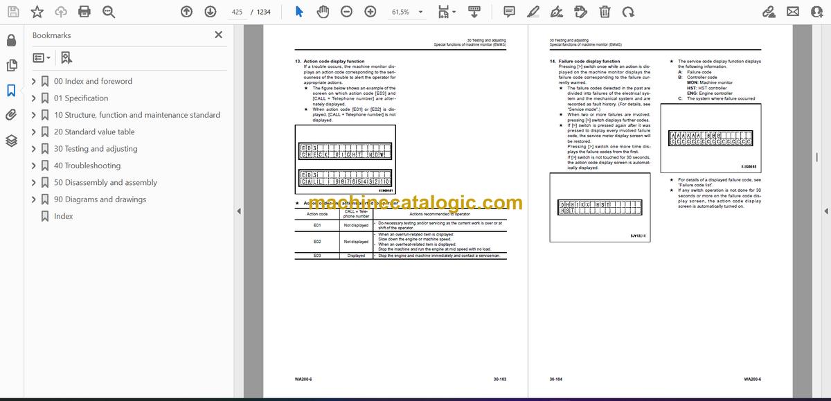
- Special functions of machine monitor (EMMS)
- Pm clinic
- Pm clinic inspection chart
- 40 Troubleshooting
- Related information on troubleshooting
- Points to remember when performing troubleshooting
- How to proceed in troubleshooting
- Testing before troubleshooting
- Checking water pump for water leakage
- Classification and procedures of troubleshooting
- Phenomena looking like troubles and troubleshooting Nos.
- Information in troubleshooting table
- Troubleshooting method for open circuit in wiring harness of pressure sensor system
- Connection table for connector pin numbers
- T- branch box and T- branch adapter table
- Fuse location
- Failure codes table
- Troubleshooting by failure code (Display of code)
- Failure code [2G40ZG] Brake : Low oil pressure
- Failure code [6091NX] HST filter : Clogging
- Failure code [989FN1] Travel speed : Overrun alarm
- Failure code [AB00L6] Alternator R system : Hot short
- Failure code [AB00MA] Alternator R system : Ground fault/ Open circuit/Low charge level
- Failure code [B@BAZG] Engine : Low oil pressure
- Failure code [B@BCNS] Engine : Overheat
- Failure code [B@BCZK] Engine : Low coolant level
- Failure code [B@C6NS] Front brake : Oil temperature overheat
- Failure code [B@CRNS] HST : Oil temperature overheat
- Failure code [CA111] Engine controller : Internal failure
- Failure code [CA115] Engine Ne and Bkup speed sensor : Error
- Failure code [CA122] Charge air pressure sensor : High error
- Failure code [CA123] Charge air pressure sensor : Low error
- Failure code [CA131] Throttle sensor : High error
- Failure code [CA132] Throttle sensor : Low error
- Failure code [CA144] Coolant temperature sensor : High error
- Failure code [CA145] Coolant temperature sensor : Low error
- Failure code [CA153] Charge air temperature sensor : High error
- Failure code [CA154] Charge air temperature sensor : Low error
- Failure code [CA155] Charge air temperature : High speed derate
- Failure code [CA187] Sensor power supply 2 voltage : Low error
- Failure code [CA221] Ambient pressure sensor : High error
- Failure code [CA222] Ambient pressure sensor : Low error
- Failure code [CA227] Sensor power supply 2 voltage : High error
- Failure code [CA234] Engine : Overspeed
- Failure code [CA238] Ne Speed sensor : Power supply voltage error
- Failure code [CA271] IMV (IMA): Short circuit
- Failure code [CA272] IMV (IMA): Open circuit
- Failure code [CA322] Injector #1 system : Open/Short circuit
- Failure code [CA324] Injector #3 system : Open/Short circuit
- Failure code [CA331] Injector #2 system : Open/Short circuit
- Failure code [CA332] Injector #4 system : Open/Short circuit
- Failure code [CA342] Engine controller : Data mismatching
- Failure code [CA351] Injectors Drive Circuit : Error
- Failure code [CA352] Sensor power supply 1 voltage : Low error
- Failure code [CA386] Sensor power supply voltage 1 : High error
- Failure code [CA428] Water-in-fuel sensor : High error
- Failure code [CA429] Water-in-fuel sensor : Low error
- Failure code [CA431] Idle validation switch : Error
- Failure code [CA432] Idle validation switch : Action error
- Failure code [CA435] Engine oil pressure switch : Error
- Failure code [CA441] Power supply voltage : Low error
- Failure code [CA442] Power supply voltage : High error
- Failure code [CA449] Common rail pressure : High error 2
- Failure code [CA451] Common rail pressure sensor : High error
- Failure code [CA452] Common rail pressure sensor : Low error
- Failure code [CA488] Charge temperature : High torque derate
- Failure code [CA553] Common rail pressure : High error
- Failure code [CA559] Supply Pump : Low rail pressure 1
- Failure code [CA689] Engine Ne speed sensor : Error
- Failure code [CA731] Engine Bkup speed sensor : Phase error
- Failure code [CA757] Engine controller : Lost of all data
- Failure code [CA778] Engine Bkup speed sensor : Error
- Failure code [CA1633] KOMNET : Error
- Failure code [CA2185] Throttle sensor power supply voltage : High error
- Failure code [CA2186] Throttle sensor power supply voltage : Low error
- Failure code [CA2249] Supply pump : Low rail pressure 2
- Failure code [CA2311] IMV (IMA) Solenoid : Error
- Failure code [CA2555] Intake heater relay : Open circuit
- Failure code [CA2556] Intake heater relay : Short circuit
- Failure code [D160KY] Backup alarm/lamp relay 1 circuit: Hot short
- Failure code [D1B0KA] HST safety relay: Disconnection
- Failure code [D1B0KB] HST safety relay: Ground fault
- Failure code [D1B0KY] HST safety relay: Hot short
- Failure code [D5ZHL6] IGN C system: Ground fault/ Disconnection
- Failure code [DAF3KK] UNSW power supply: Ground fault/ Disconnection
- Failure code [DAFRKR] Machine monitor CAN-NET Signal: Disconnection
- Failure code [DAJ0KK] HST controller power supply: Low voltage
- Failure code [DAJ0KT] HST controller memory (EEPROM): Abnormality
- Failure code [DAJ1L4] HST controller main power supply line: Disconnection/Ground fault
- Failure code [DAJ1L6] HST controller main power supply line: Hot short
- Failure code [DAJ2KK] Controller solenoid power supply: Low voltage
- Failure code [DAJ2L3] HST controller load power supply holding line: Hot short
- Failure code [DAJ2L4] HST controller load power supply holding line: Disconnection/Ground fault
- Failure code [DAJ5KX] Sensor 5V power supply: Out of input range
- Failure code [DAJ9KQ] HST controller : Disagreement in model selection
- Failure code [DAJRKR] HST controller CAN-NET signal: Disconnection
- Failure code [DAJRMA] HST controller: Disagreement in option selection
- Failure code [DB2RKR] Engine controller CAN-NET signal: Disconnection
- Failure code [DD1NL4] Fan Auto Reverse Switch Signal : Abnormality
- Failure code [DD1NLD] Fan Reverse Switch Signal: Abnormal
- Failure code [DDB6KA] Parking brake reminder signal: Disconnection/Hot short
- Failure code [DDB6KB] Parking brake indicator signal: Ground fault
- Failure code [DDB6KZ] Parking brake indicator signal or parking brake reminder signal : Failure
- Failure code [DDB6L0] Parking brake reminder signal: Ground fault
- Failure code [DDB6L4] Parking brake indicator signal: Disconnection/Hot short
- Failure code [DDD7KX] Travel speed control dial signal: Disconnection/Ground fault
- Failure code [DDD7KY] Travel speed control dial signal: Hot short
- Failure code [DDE5MA] Emergency steering operation switch: Disconnection
- Failure code [DDK6KA] FNR lever: Disconnection/Ground fault
- Failure code [DDK6KY] FNR lever: Hot short
- Failure code [DDS5L6] Steering: Low oil pressure (Operation of emergency steering)
- Failure code [DF10KA] Travel speed range selector switch: Disconnection/Ground fault
- Failure code [DF10KB] Travel speed range selector switch: Hot short
- Failure code [DGH1KX] HST oil temperature sensor: Ground fault
- Failure code [DGR2KB] Brake oil temperature sensor: Ground fault
- Failure code [DGR2KZ] Brake oil temperature sensor : Disconnection/Hot short
- Failure code [DHH1KX] HST oil pressure sensor: Disconnection/Ground fault
- Failure code [DHH1KY] HST oil pressure sensor: Hot short
- Failure code [DHTCL6] HST filter clogging sensor: Functional defect
- Failure code [DJF1KA] Fuel level sensor: Disconnection/Hot short
- Failure code [DLT3KX] Travel speed sensor B: Abnormality
- Failure code [DLT4KX] Travel speed sensor A: Abnormality
- Failure code [DLT4LC] Travel speed sensor A & B: Abnormality
- Failure code [DV00KY] Alarm buzzer: Hot short
- Failure code [DW26KA] Motor 2 solenoid: Disconnection/Ground fault
- Failure code [DW26KY] Motor 2 solenoid: Hot short
- Failure code [DW7BKY] Fan reverse solenoid circuit: Hot short
- Failure code [DW7BKZ] Fan reverse solenoid circuit: Disconnection/Ground fault
- Failure code [DX16KA] Fan EPC solenoid: Disconnection
- Failure code [DX16KB] Fan EPC solenoid: Ground fault
- Failure code [DX16KY] Fan EPC solenoid: Hot short
- Failure code [DX19KA] Motor 1 solenoid: Disconnection
- Failure code [DX19KB] Motor 1 solenoid: Ground fault
- Failure code [DX19KY] Motor 1 solenoid: Hot short
- Failure code [DX20KA] Clutch EPC solenoid: Disconnection
- Failure code [DX20KB] Clutch EPC solenoid: Ground fault
- Failure code [DX20KY] Clutch EPC solenoid: Hot short
- Failure code [DXH7KB] Reverse solenoid : Ground fault
- Failure code [DXH7KZ] Reverse solenoid: Disconnection/Hot short
- Failure code [DXH8KB] Forward solenoid : Ground fault
- Failure code [DXH8KZ] Forward solenoid: Disconnection/Hot short
- Failure code [J141N1] Steering pump: Overrun alarm
- Failure code [M100N1] HST pump: Overrun alarm
- Failure code [M400N1] Motor 1: Overrun alarm
- Troubleshooting of electrical system (E-mode)
- E-1 Engine does not start
- E-2 Preheater does not operate normally
- E-3 When starting switch is turned to ON position, nothing is displayed on machine monitor
- E-4 Travel speed is not displayed correctly
- E-5 Travel speed is low or high
- E-6 Boom kick-out does not work or is not reset
- E-7 Bucket positioner does not work or is not reset
- E-8 Boom FLOAT holding does not work or is not reset
- E-9 Directional selection does not work normally
- E-10 Wipers do not operate
- E-11 Window washer does not operate
- E-12 Headlamp, clearance lamp, tail lamp or license-plate lamp does not light up or does not go out
- E-13 Working lamp does not light up or does not go out
- E-14 Turn signal and hazard lamp do not light up or do not go out
- E-15 Stop lamp does not light up or remains lighting up
- E-16 Backup lamp does not light or it keeps lighting up
- E-17 Backup alarm does not sound or does not stop sounding
- E-18 Horn does not sound or does not stop sounding
- E-19 Alarm buzzer does not sound or does not stop sounding
- E-20 Troubleshooting of air conditioner
- E-21 KOMTRAX system does not operate normally
- Troubleshooting of hydraulic and mechanical system (H-mode)
- Method of using troubleshooting chart
- Failure code and cause table
- H-1 The machine does not start
- H-2 The travel speed is slow
- H-3 The traction force is weak
- H-4 Engine stalls when traveling or engine speed drops excessively
- H-5 Speed range is not shifted
- H-6 The steering wheel does not turn
- H-7 The steering wheel is heavy
- H-8 Steering wheel shakes or jerks
- H-9 Machine deviates naturally to one side when traveling
- H-10 The brake does not work or does not work well
- H-11 The brake is not released or is dragged
- H-12 The boom does not rise or lower
- H-13 The boom moves slowly or the lift arm rising force is insufficient
- H-14 When rising, the boom comes to move slowly at specific height
- H-15 The lift cylinder cannot hold down the bucket (The bucket rises in the air)
- H-16 Hydraulic drifts of the boom are large
- H-17 The boom wobbles during operation
- H-18 When the control lever is switched from “HOLD” to “RAISE,” the boom falls temporarily
- H-19 The bucket does not tilt back
- H-20 The bucket moves slowly or the tilting-back force is insufficient
- H-21 The bucket comes to operate slowly in the midst of tilting-back
- H-22 The bucket cylinder cannot hold down the bucket
- H-23 Hydraulic drifts of the bucket occur often
- H-24 The bucket wobbles during travel with load (The work equipment valve is set to “HOLD”)
- H-25 When the control lever is switched from “HOLD” to “TILT,” the bucket falls temporarily
- H-26 The control levers of the boom and bucket do not move smoothly and heavy
- H-27 Fan revolution is abnormal (Fan sound/vibration is abnormally large or engine overheats)
- Troubleshooting of engine (S-mode)
- Method of using troubleshooting charts
- S-1 Starting performance is poor
- S-2 Engine does not start
- S-3 Engine does not pick up smoothly
- S-4 Engine stops during operations
- S-5 Engine does not rotate smoothly
- S-6 Engine lacks output (or lacks power)
- S-7 Exhaust smoke is black (incomplete combustion)
- S-8 Oil consumption is excessive (or exhaust smoke is blue)
- S-9 Oil becomes contaminated quickly
- S-10 Fuel consumption is excessive
- S-11 Oil is in coolant (or coolant spurts back or coolant level goes down)
- S-12 Oil pressure drops
- S-13 Oil level rises (Entry of coolant or fuel)
- S-14 Coolant temperature becomes too high (overheating)
- S-15 Abnormal noise is made
- S-16 Vibration is excessive
- 50 Disassembly and assembly
- General information on disassembly and assembly
- How to read this manual
- Coating materials list
- Special tool list
- Sketches of special tools
- Engine and cooling system
- Removal and installation of fuel supply pump assembly
- Removal and installation of fuel injector assembly
- Removal and installation of cylinder head assembly
- Removal and installation engine hood assembly
- Removal and installation of radiator
- Removal and installation of air aftercooler
- Removal and installation of hydraulic oil cooler assembly
- Removal and installation of engine assembly
- Removal and installation of engine front oil seal assembly
- Removal and installation of engine rear oil seal assembly
- Removal and installation of cooling fan and fan motor assembly
- Removal and installation of fuel tank assembly
- Power train
- Removal and installation of transfer assembly
- Disassembly and assembly of transfer assembly
- Removal and installation of parking brake assembly
- Disassembly and assembly of parking brake assembly
- Removal and installation of front axle assembly
- Removal and installation of rear axle assembly
- Disassembly and assembly of axle housing assembly
- Disassembly and assembly of differential assembly
- Undercarriage and frame
- Removal and installation of center hinge pin
- Removal and installation of counterweight assembly
- Hydraulic system
- Removal and installation of HST pump and quadruple gear pump assembly
- Removal and installation of HST motor 1 assembly
- Removal and installation of HST motor 2 assembly
- Removal and installation of work equipment control valve assembly
- Removal and installation of hydraulic tank
- Disassembly and assembly of hydraulic cylinder assembly
- Work equipment
- Removal and installation of work equipment assembly
- Cab and its attachments
- Removal and installation of operator's cab and floor frame assembly
- Removal and installation of operator's cab glass (Stuck glass)
- Removal and installation of operator's seat assembly
- Removal and installation of air conditioner unit
- Electrical system
- Removal and installation of monitor panel
- Removal and installation of engine controller assembly
- Removal and installation of HST controller assembly
- Removal and installation of KOMTRAX terminal (ORBCOMM) assembly
- Removal and installation of KOMTRAX terminal (GPRS) assembly
- 90 Diagrams and drawings
- Hydraulic diagrams and drawings
- Symbols used in hydraulic circuit diagrams
- Hydraulic circuit diagram
- Electrical diagrams and drawings
- Symbols used in electric circuit diagrams
- Electrical circuit diagram
- Electrical circuit diagram for CIS
- Electrical circuit diagram of engine and HST
- Connector list and stereogram
- Connector list and stereogram (CIS specification)
- Index
Komatsu


