These Komatsu WA320-6 and WA320PZ-6 wheel loaders are mid-size yard and jobsite machines, usually doing load-out, stockpile work, and general material handling. The Komatsu WA320-6, WA320PZ-6 Wheel Loader Shop Manual (SEN03911-15) is what shop guys and field techs reach for when something’s broken, out of spec, or coming apart on the bench. People buying this are usually trying to chase electrical or hydraulic faults, rebuild major components, or verify assembly order after a teardown. It’s a repair book, not an operator’s booklet.
What this manual helps you do
- Trace hydraulic issues in the loader and steering circuits using the kind of diagnostic flow you’d expect in a factory shop manual.
- Diagnose electrical faults in charging, starting, lighting, and control systems with wiring diagrams and step-by-step test logic.
- Follow disassembly and reassembly sequences for engine-related components, powertrain parts, axles, and brake groups.
- Check adjustment procedures for linkages, travel and work equipment controls, and machine settings after repairs.
- Handle removal and installation of major assemblies on the WA320-6 and WA320PZ-6 with the correct order of operations and safety notes.
The Shop Manual for Komatsu WA320-6, WA320PZ-6 Wheel Loader walks through diagnostic procedures, disassembly sequences, and reference data used during workshop-level repairs. In my experience, this is what most shops use as the base document for heavy repairs on these loaders.
Who this is for
This fits a field tech, dealership mechanic, or fleet shop that actually turns wrenches on these specific loaders. If you’re just running the machine or planning daily services only, you want the Operation & Maintenance manual instead, not this one.
FAQ
Q: Is this a PDF I can search and print?
A: Yes, it’s typically a searchable PDF you can view on a laptop or tablet and print individual pages for use in the shop.
Q: Is this enough for full rebuild work, or just basic checks?
A: This kind of shop manual usually covers full system diagnostics, teardown, and reassembly, so it’s aimed at full repair work, not just quick inspections.
Q: How do I know if it matches my exact machine version?
A: Check your machine’s model designation and book reference; if your loader is a WA320-6 or WA320PZ-6 and you’re matching SEN03911-15, you’re in the right neighborhood.
Bottom line: if you’re repairing or overhauling WA320-6 or WA320PZ-6 loaders, this is the right manual; if you only need operating tips or service intervals, keep looking for the O&M book instead.
📘 Show Index
Table of Contents:
- 00 Index and foreword
- 100 Index
- Composition of shop manual
- Table of contents
- 200 Foreword and general information
- Safety notice
- How to read the shop manual
- Explanation of terms for maintenance standard
- Handling of electric equipment and hydraulic component
- Handling of connectors newly used for engines
- How to read electric wire code
- Precautions when carrying out operation
- Method of disassembling and connecting push-pull type coupler
- Standard tightening torque table
- Conversion table
- 01 Specification
- 100 Specification and technical data
- Specification dimension drawing
- Specifications
- Weight table
- Table of fuel, coolant and lubricants
- 10 Structure, function and maintenance standard
- 100 Engine and cooling system
- Engine mount and transfer mount
- Damper
- Cooling system
- Cooling system hydraulic piping diagram
- Cooling fan motor
- 200 Power train
- Power train
- Power train system diagram
- Drive shaft
- HST hydraulic piping diagram
- HST pump
- HST motor
- Transfer
- Clutch solenoid valve
- Axle
- Differential
- Torque proportioning differential
- Limited slip differential
- Final drive
- 300 Steering system
- Steering piping diagram
- Steering column
- Priority valve
- Orbit-roll valve
- Cushion valve
- Steering cylinder
- Emergency steering piping diagram
- Emergency steering valve
- Steering relief valve
- 400 Brake system
- Brake piping diagram
- Charge valve
- Brake valve
- Inching valve
- Accumulator (for brake)
- Slack adjuster
- Brake
- Parking brake control
- Parking brake
- 500 Undercarriage and frame
- Axle mount and center hinge pin
- Tires
- 600 Hydraulic system
- Work equipment hydraulic piping diagram
- Work equipment control lever linkage
- Hydraulic tank
- 4-gear pump
- Work equipment control valve
- Cut-off valve
- PPC valve
- Lock valve
- Accumulator (for PPC circuit)
- ECSS valve
- Accumulator (for ECSS)
- 700 Work equipment
- Work equipment linkage
- Bucket
- Bucket positioner and boom kick-out
- Work equipment cylinder
- 800 Cab and its attachments
- 910 Electrical system, Part 1
- Machine monitor system
- Machine monitor
- 920 Electrical system, Part 2
- Electrical system (HST controller system)
- HST controller
- ECSS system
- KOMTRAX system
- Engine starting circuit
- Engine stopping circuit
- Preheating circuit
- Engine output derating function
- Automatic warm-up function
- Parking brake circuit
- Coupler plunger control system
- Multi-function knob
- Max. traction switch
- Sensor
- 20 Standard value table
- 100 Standard service value table
- Standard service value table for engine
- Standard service value table for chassis
- 30 Testing and adjusting
- 110 Testing and adjusting, Part 1
- Tools for testing, adjusting, and troubleshooting
- Measuring engine speed
- Measuring exhaust gas color
- Adjusting valve clearance
- Measuring compression pressure
- Measuring blow-by pressure
- Measuring engine oil pressure
- Measuring intake air (boost) pressure
- Handling fuel system equipment
- Releasing residual pressure in fuel system
- Measuring fuel pressure
- Measuring fuel return rate and leakage
- Bleeding air from fuel circuit
- Checking leakage in fuel system
- Handling cylinder cut-out mode operation
- Handling no-injection cranking operation
- Handling controller voltage circuit
- Check of muffler and muffler stack for looseness and damage
- Check of muffler function
- Check of installed condition of cylinder head and manifolds
- Check of engine piping for damage and looseness
- Testing and adjusting air conditioner compressor belt tension
- Replacing alternator belt
- 120 Testing and adjusting, Part 2
- Checking operating force of accelerator pedal
- Checking directional lever
- Testing and adjusting HST oil pressure
- Testing clutch control pressure
- Testing and adjusting steering wheel
- Testing and adjusting steering oil pressure
- Bleeding air from steering circuit
- Testing hydraulic fan
- Measuring brake pedal
- Testing and adjusting brake pedal linkage
- Measuring brake performance
- Testing and adjusting accumulator charge pressure
- Testing wheel brake oil pressure
- Testing wear of brake disc
- Bleeding air from wheel brake circuit
- Releasing residual pressure in brake accumulator circuit
- Testing parking brake performance
- Testing and adjusting parking brake control cable
- Measuring and adjusting work equipment control lever
- Testing and adjusting worke quipment hydraulic pressure
- Testing work equipment PPC oil pressure
- Bleeding air from hydraulic circuit
- Releasing remaining pressure in hydraulic circuit
- Testing and adjusting bucket positioner
- Testing and adjusting of boom kick-out switch
- Checking proximity switch operation pilot lamp
- Procedure for testing diodes
- Preparation work for troubleshooting for electric system
- Starting KOMTRAX terminal operations
- Indicator lamps of KOMTRAX terminal
- 130 Testing and adjusting, Part 3
- Adjusting machine monitor
- Adjusting replaced, reassembled or added sensor, controller, etc. with machine monitor
- Special functions of machine monitor (EMMS)
- Pm clinic inspection chart
- 40 Troubleshooting
- 100 Failure code table and fuse locations
- Failure codes table
- Fuse locations
- 200 General information on troubleshooting
- Points to remember when troubleshooting
- Sequence of events in troubleshooting
- Testing before troubleshooting
- Checking water pump for water leakage
- Classification and procedures of troubleshooting
- Information contained in troubleshooting table
- Connection table for connector pin numbers
- T- branch box and T- branch adapter table
- 310 Troubleshooting by failure code (Display of code), Part 1
- Failure code [2G40ZG] Brake: Oil pressure reduction
- Failure code [6091NX] HST filter: Clogging
- Failure code [989FN1] Travel speed: Overrun alarm
- Failure code [AA1ANX] Air cleaner: Clogging
- Failure code [AB00L6] Alternator R system: Hot short
- Failure code [AB00MA] Alternator R system: Ground fault/Disconnection/Low charge voltage
- Failure code [B@BAZG] Engine: Oil pressure reduction
- Failure code [B@BAZK] Engine oil: Low level
- Failure code [B@BCNS] Engine: Overheat
- Failure code [B@BCZK] Engine: Low coolant level
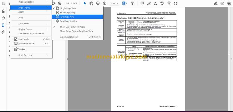
- Failure code [B@C6NS] Front brake: High oil temperature
- Failure code [B@CRNS] HST: High oil temperature
- 320 Troubleshooting by failure code (Display of code), Part 2
- Failure code [CA111] Abnormality in engine controller
- Failure code [CA115] Engine Ne or Bkup speed sensor error
- Failure code [CA122] Charge pressure sensor high error
- Failure code [CA123] Charge pressure sensor low error
- Failure code [CA131] Throttle sensor high error
- Failure code [CA132] Throttle sensor low error
- Failure code [CA144] Coolant sensor high error
- Failure code [CA145] Coolant sensor low error
- Failure code [CA153] Charge temperature sensor high error
- Failure code [CA154] Charge temperature sensor low error
- Failure code [CA155] Derating of speed by abnormally high charge temperature
- Failure code [CA187] Sensor power supply 2 low error
- Failure code [CA221] Atmospheric pressure sensor high error
- Failure code [CA222] Atmospheric sensor low error
- Failure code [CA227] Sensor power supply 2 high error
- Failure code [CA234] Engine overspeed
- Failure code [CA238] Ne speed sensor power supply error
- Failure code [CA271] IMV (IMA) Short circuit
- Failure code [CA272] IMV (IMA) Disconnection
- Failure code [CA322] Injector #1 open/short error
- Failure code [CA323] Injector #5 open/short error
- Failure code [CA324] Injector #3 open/short error
- Failure code [CA325] Injector #6 open/short error
- Failure code [CA331] Injector #2 open/short error
- Failure code [CA332] Injector #4 open/short error
- Failure code [CA342] Calibration code inconsistency
- Failure code [CA351] Injectors drive circuit error
- Failure code [CA352] Sensor power supply 1 low error
- Failure code [CA386] Sensor power supply 1 high error
- 330 Troubleshooting by failure code (Display of code), Part 3
- Failure code [CA428] Abnormally high level in water sensor
- Failure code [CA429] Abnormally low level in water sensor
- Failure code [CA431] Idle validation switch error
- Failure code [CA432] Idle validation action error
- Failure code [CA435] Engine oil pressure switch error
- Failure code [CA441] Battery voltage low error
- Failure code [CA442] Battery voltage high error
- Failure code [CA449] Common rail pressure high error 2
- Failure code [CA451] Common rail pressure sensor high error
- Failure code [CA452] Common rail pressure sensor low error
- Failure code [CA488] Derating of torque by abnormally high charge temperature
- Failure code [CA553] Common rail pressure high error 1
- Failure code [CA559] Supply pump pressure very low error
- Failure code [CA689] Engine Ne speed sensor error
- Failure code [CA731] Engine Bkup speed sensor phase error
- Failure code [CA757] All continuous data lost error
- Failure code [CA778] Engine Bkup speed sensor error
- Failure code [CA1633] KOMNET datalink timeout error
- Failure code [CA2185] Throttle sensor supply voltage high error
- Failure code [CA2186] Throttle sensor power supply low error
- Failure code [CA2249] Supply pump pressure very low error 2
- Failure code [CA2311] Abnormality in IMV (IMA) solenoid
- Failure code [CA2555] Intake heater relay disconnection error
- Failure code [CA2556] Intake heater relay short circuit error
- 340 Troubleshooting by failure code (Display of code), Part 4
- Failure code [D160KY] Backup alarm/lamp relay 1 circuit: Hot short
- Failure code [D192KY] ECSS solenoid relay: Hot short
- Failure code [D1B0KA] HST safety relay: Disconnection
- Failure code [D1B0KB] HST safety relay: Ground fault
- Failure code [D1B0KY] HST safety relay: Hot short
- Failure code [D5ZHL6] IGN C system: Ground fault/Disconnection
- Failure code [DAF3KK] UNSW power supply: Ground fault/Disconnection
- Failure code [DAFRKR] Machine monitor CAN-NET Signal: Disconnection
- Failure code [DAJ0KK] HST controller power supply: Low voltage
- Failure code [DAJ0KT] HST controller memory (EEPROM): Abnormality
- Failure code [DAJ1L4] HST controller main power line: Disconnection/Ground fault
- Failure code [DAJ1L6] HST controller main power line: Hot short
- Failure code [DAJ2KK] Controller solenoid power supply: Low voltage
- Failure code [DAJ2L3] HST controller load power supply holding line: Hot short in wiring harness
- Failure code [DAJ2L4] HST controller load power supply holding line: Disconnection/Ground fault
- Failure code [DAJ5KX] Sensor 5V power supply: Out of output range
- Failure code [DAJ9KQ] HST controller model selection: Disagreement of model selection signals
- Failure code [DAJRKR] HST controller CAN-NET signal: Disconnection
- Failure code [DAJRMA] HST controller: Disagreement in option selection
- 350 Troubleshooting by failure code (Display of code), Part 5
- Failure code [DB2RKR] Engine controller CAN-NET: Disconnection in signal line
- Failure code [DD1NL4] Fan automatic reverse switch signal: Abnormality
- Failure code [DD1NLD] Fan reverse switch signal: Abnormality
- Failure code [DDB6KA] Parking brake reminder signal: Disconnection/Hot short
- Failure code [DDB6KB] Parking brake indicator signal: Ground fault
- Failure code [DDB6KZ] Parking brake switch (bottom switch) or parking brake reminder switch (intermediate switch): Trouble
- Failure code [DDB6L0] Parking brake reminder signal: Ground fault
- Failure code [DDB6L4] Parking brake indicator signal: Disconnection/Hot short
- Failure code [DDD7KX] Travel speed control dial signal: Disconnection/Ground fault
- Failure code [DDD7KY] Travel speed control dial signal: Hot short
- Failure code [DDE5MA] Emergency steering operation switch: Disconnection
- Failure code [DDK3KA] Directional selector switch: Disconnection/Hot short
- Failure code [DDK3KB] Directional selector switch: Ground fault
- Failure code [DDK6KA] FNR lever: Disconnection/Ground fault
- Failure code [DDK6KY] FNR lever: Hot short
- Failure code [DDS5L6] Steering: Low oil pressure (Operation of emergency steering)
- 360 Troubleshooting by failure code (Display of code), Part 6
- Failure code [DF10KA] Travel speed range selector switch: Disconnection/Ground fault
- Failure code [DF10KB] Travel speed range selector switch: Hot short
- Failure code [DGH1KX] HST oil temperature sensor: Ground fault
- Failure code [DGR2KB] Brake oil temperature sensor: Ground fault
- Failure code [DGR2KZ] Brake oil temperature sensor: Disconnection/ Hot short
- Failure code [DHH1KX] HST oil pressure sensor: Disconnection/Ground fault
- Failure code [DHH1KY] HST oil pressure sensor: Hot short
- Failure code [DHTCL6] HST filter clogging sensor: Functional defect
- Failure code [DJF1KA] Fuel level sensor: Disconnection/Hot short
- Failure code [DLT3KX] Travel speed sensor B: Abnormality
- Failure code [DLT4KX] Travel speed sensor A: Abnormality
- Failure code [DLT4LC] Travel speed sensor A & B: Abnormality
- Failure code [DV00KY] Alarm buzzer: Hot short
- Failure code [DW26KA] Motor 2 solenoid: Disconnection/Ground fault
- Failure code [DW26KY] Motor 2 solenoid: Hot short
- Failure code [DW7BKY] Fan reverse solenoid circuit: Hot short
- Failure code [DW7BKZ] Fan reverse solenoid circuit: Disconnection/ Ground fault
- 370 Troubleshooting by failure code (Display of code), Part 7
- Failure code [DX16KA] Fan EPC solenoid: Disconnection
- Failure code [DX16KB] Fan EPC solenoid: Ground fault
- Failure code [DX16KY] Fan EPC solenoid: Hot short
- Failure code [DX19KA] Motor 1 solenoid: Disconnection
- Failure code [DX19KB] Motor 1 solenoid: Ground fault
- Failure code [DX19KY] Motor 1 solenoid: Hot short
- Failure code [DX20KA] Clutch EPC solenoid: Disconnection
- Failure code [DX20KB] Clutch EPC solenoid: Ground fault
- Failure code [DX20KY] Clutch EPC solenoid: Hot short
- Failure code [DXH7KB] Reverse solenoid: Ground fault
- Failure code [DXH7KZ] Reverse solenoid: Disconnection/Hot short
- Failure code [DXH8KB] Forward solenoid: Ground fault
- Failure code [DXH8KZ] Forward solenoid: Disconnection/Hot short
- Failure code [J141N1] Steering pump: Overrun alarm
- Failure code [M100N1] HST pump: Overrun alarm
- Failure code [M400N1] Motor 1: Overrun alarm
- 400 Troubleshooting of electrical system (E-mode)
- E-1 Engine does not start
- E-2 Preheater does not operate normally
- E-3 Travel speed is low or high
- E-4 ECSS does not operate
- E-5 ECSS keeps operating
- E-6 Defective boom kick-out function and cancellation
- E-7 Defective bucket positioner function and cancellation
- E-8 Defective lift arm FLOATING holding function and cancellation
- E-9 Travel direction selection system does not function
- E-10 Fan does not reverse
- E-11 Fan keeps rotating in reverse
- E-12 Wiper does not operate
- E-13 Windshield washer does not operate
- E-14 Headlamp, clearance lamp and tail lamp do not light up or go off
- E-15 Working lamp does not light up or go off
- E-16 Turn signal lamp and hazard lamp do not light up or go off
- E-17 Brake lamp does not light or it keeps lighting up
- E-18 Backup lamp does not light or it keeps lighting up
- E-19 Backup alarm does not sound or it keeps sounding
- E-20 Horn does not sound or it keeps sounding
- E-21 Alarm buzzer does not sound or it keeps sounding
- E-22 Air conditioner does not operate or stop
- E-23 The KOMTRAX system does not work properly
- 500 Troubleshooting of hydraulic and mechanical system (H-mode)
- Method of using troubleshooting chart
- Failure code and cause table
- H-1 The machine does not start
- H-2 The travel speed is slow
- H-3 The traction force is weak
- H-4 Engine stalls when traveling or engine speed drops excessively
- H-5 Shift range is not shifted
- H-6 The steering wheel does not turn
- H-7 The steering wheel is heavy
- H-8 Steering wheel shakes or jerks
- H-9 Machine deviates naturally to one side when traveling
- H-10 The brake does not work or does not work well
- H-11 The brake is not released or is dragged
- H-12 The lift arm does not rise or lower
- H-13 The lift arm moves slowly or the lift arm rising force is insufficient
- H-14 When rising, the lift arm comes to move slowly at specific height
- H-15 The lift arm cylinder cannot hold down the bucket (The bucket rises in the air)
- H-16 Hydraulic drifts of the lift arm occur often
- H-17 The lift arm wobbles during operation
- H-18 When the control lever is switched from “HOLD” to “RAISE,” the lift arm falls temporarily
- H-19 The bucket does not tilt back
- H-20 The bucket moves slowly or the tilting-back force is insufficient
- H-21 The bucket comes to operate slowly in the midst of tilting-back
- H-22 The bucket cylinder cannot hold down the bucket
- H-23 Hydraulic drifts of the bucket occur often
- H-24 The bucket wobbles during travel with load (The work equipment valve is set to “HOLD”)
- H-25 When the control lever is switched from “HOLD” to “TILT,” the bucket falls temporarily
- H-26 The control levers of the lift arm and bucket do not move smoothly and heavy
- H-27 The ECSS does not operate and machine pitches and bounces
- H-28 Fan revolution is abnormal (Fan sound/vibration is abnormally large or engine overheats)
- 600 Troubleshooting of engine (S-mode)
- Method of using troubleshooting charts
- S-1 Starting performance is poor
- S-2 Engine does not start
- S-3 Engine does not pick up smoothly
- S-4 Engine stops during operations
- S-5 Engine does not rotate smoothly
- S-6 Engine lacks output (or lacks power)
- S-7 Exhaust smoke is black (incomplete combustion)
- S-8 Oil consumption is excessive (or exhaust smoke is blue)
- S-9 Oil becomes contaminated quickly
- S-10 Fuel consumption is excessive
- S-11 Oil is in coolant (or coolant spurts back or coolant level goes down)
- S-12 Oil pressure drops
- S-13 Oil level rises (Entry of coolant or fuel)
- S-14 Coolant temperature becomes too high (overheating)
- S-15 Abnormal noise is made
- S-16 Vibration is excessive
- 50 Disassembly and assembly
- 100 General information on disassembly and assembly
- How to read this manual
- Coating materials list
- Special tool list
- Sketches of special tools
- 200 Engine and cooling system
- Removal and installation of fuel supply pump assembly
- Removal and installation of fuel injector assembly
- Removal and installation of cylinder head assembly
- Removal and installation of engine hood assembly
- Removal and installation of radiator
- Removal and installation of air aftercooler
- Removal and installation of hydraulic oil cooler assembly
- Removal and installation of engine assembly
- Removal and installation of engine front oil seal assembly
- Removal and installation of engine rear oil seal assembly
- Removal and installation of cooling fan and fan motor assembly
- Removal and installation of fuel tank assembly
- 310 Power train, Part 1
- Removal and installation of transfer
- Disassembly and assembly of transfer assembly
- Removal and installation of parking brake assembly
- Disassembly and assembly of parking brake assembly
- 320 Power train, Part 2
- Removal and installation of front axle assembly
- Removal and installation of rear axle assembly
- Disassembly and assembly of axle housing assembly
- Disassembly and assembly of differential assembly (Serial number: 70001 to 73494)
- Disassembly and assembly of differential assembly (Serial number: 73495 and up)
- 400 Undercarriage and frame
- Removal and installation of center hinge pin
- Removal and installation of counterweight
- 500 Hydraulic system
- Removal and installation of HST pump and 4-gear pump assembly
- Disassembly and assembly of HST pump assembly
- Removal and installation of HST motor 1 assembly
- Removal and installation of HST motor 2 assembly
- Disassembly and assembly of HST motor assembly
- Removal and installation of work equipment control valve assembly
- Removal and installation of hydraulic tank assembly
- Disassembly and assembly of hydraulic cylinder assembly
- 600 Work equipment
- Removal and installation of work equipment assembly
- 700 Cab and its attachments
- Removal and installation of operator's cab and floor frame assembly
- Removal and installation of operator's cab glass (Stuck glass)
- Disassembly and assembly of operator's seat assembly
- Removal and installation of air conditioner unit
- 800 Electrical system
- Removal and installation of monitor panel
- Removal and installation of engine controller assembly
- Removal and installation of HST controller assembly
- Removal and installation of KOMTRAX terminal assembly
- 90 Diagrams and drawings
- 100 Hydraulic diagrams and drawings
- Automatic greasing circuit diagram
- Hydraulic circuit diagram
- 200 Electrical diagrams and drawings
- Common electrical circuit diagram
- Connector list and stereogram
Komatsu


