Komatsu WA380-6, WA380Z-6 Wheel Loader Shop Manual (SMEW380602-00)
The Komatsu WA380-6, WA380Z-6 Wheel Loader Shop Manual (SMEW380602-00) is the workshop guide for doing actual repairs on these mid-size loaders, not just daily checks. This is what shop mechanics, field techs, and serious owner-operators grab when a machine is down and guessing isn’t an option. People usually want it to walk through teardown, reassembly, and proper diagnostic steps so they don’t waste half a day chasing the wrong fault.
What this manual helps you do
- Trace engine and drivetrain faults on WA380-6 and WA380Z-6 loaders using step-by-step diagnostic flows and test points you can hit with basic shop tools.
- Check and adjust major components in the powertrain and hydraulic system so rebuilt or replaced parts go back in correctly the first time.
- Follow disassembly and reassembly sequences for key systems (axles, boom and bucket linkages, hydraulic pumps/valves) without wrecking seals or hardware.
- Diagnose electrical issues in the loader’s wiring and control circuits using wiring diagrams and connector callouts that match the machine.
- Handle post-repair verification checks so you can sign off a job knowing pressures, movements, and responses are behaving like they should.
Who this is for
This shop manual is aimed at field technicians, dealership or independent shop mechanics, and fleet maintenance leads who actually turn wrenches. If you’re just running the machine and want basic operation or daily service intervals, you’re better off with the Operation & Maintenance Manual instead.
FAQ
Q: Is this a PDF I can download and search or print?
A: Yes, it’s a PDF you can download, keyword-search on a laptop or tablet, and print sections for use in the shop or on site.
Q: Is it deep enough for full overhauls, or just light service?
A: This is a shop manual, so it’s intended for workshop-level repairs, diagnostics, and system overhauls on the Komatsu WA380-6 and WA380Z-6 Wheel Loader.
Q: How do I know if it matches my exact machine variant or serial range?
A: The reference code is SMEW380602-00; if your loader is a WA380-6 or WA380Z-6 and your dealer points you to this book code, you’re in the right place, otherwise confirm the book number against your machine tag.
Bottom line: if you’re the person responsible for fixing a WA380-6 or WA380Z-6 when it’s eating money sitting still, this is the manual you want; if you only need operating tips and basic maintenance, keep looking for the O&M book instead.
📘 Show Index
Komatsu WA380-6, WA380Z-6 Wheel Loader Shop Manual (SMEW380602-00) Index:
- COVER
- 00 Index and foreword
- Index
- Composition of shop manual
- Table of contents
- Foreword and general information
- Safety notice
- How to read the shop manual
- Explanation of terms for maintenance standard
- Handling of electric equipment and hydraulic component
- Handling of connectors newly used for engines
- How to read electric wire code
- Precautions when carrying out operation
- Method of disassembling and connecting push-pull type coupler
- Standard tightening torque table
- Conversion table
- 01 Specification
- Specification and technical data
- Specification dimension drawing
- Specifications
- Weight table
- Table of fuel, coolant and lubricants
- 10 Structure, function and maintenance standard
- Engine and cooling system
- Engine mount and transmission mount
- Cooling system
- Cooling fan pump
- Brake and fan pump
- Cooling fan motor
- Power train
- Power train
- Power train system diagram
- Drive shaft
- Power train piping diagram
- Torque converter
- Transmission
- Flow control valve
- Valve assembly
- ECMV
- Main relief valve and torque converter relief valve
- Axle
- Differential
- Limited slip differential
- Final drive
- Steering system
- Steering piping diagram
- Steering column
- Steering pump
- Steering valve
- Orbit-roll valve
- Stop valve
- Steering relief valve
- Steering cylinder
- Emergency steering motor
- Emergency steering pump
- Joystick steering lever linkage
- Steering electric lever
- Joystick EPC valve
- Brake system
- Brake piping diagram
- Charge valve
- Brake valve
- Accumulator (for brake)
- Brake
- Parking brake control
- Parking brake
- Parking brake solenoid valve
- Emergency parking brake release valve
- Undercarriage and frame
- Axle mount and center hinge pin
- Tires
- Hydraulic system, Part 1
- Hydraulic piping diagram
- Work equipment control lever linkage
- Hydraulic tank
- Power train pump
- Work equipment pump
- Work equipment control valve
- CLSS
- Each function and operation of each valve
- Hydraulic system, Part 2
- PPC valve
- Stabilizer valve
- Accumulator (for PPC circuit)
- Accumulator (for ECSS)
- Work equipment PPC cut-off solenoid valve
- Work equipment
- Work equipment linkage
- Bucket
- Bucket positioner and boom kick-out
- Work equipment cylinder
- Cab and its attachments
- Electrical system, Part 1
- Machine monitor system
- Machine monitor
- Electrical system, Part 2
- Electrical system (Transmission controller system)
- Transmission controller
- Electrical system (Work equipment controller system)
- Work equipment controller
- Electrical system, Part 3
- Electric transmission control
- Kickdown switch and hold switch
- Multi-function knob
- Joystick steering knob
- KOMTRAX terminal system
- Engine starting circuit
- Engine stopping circuit
- Preheating circuit
- Engine power mode selector circuit
- Engine output derating function
- Automatic warm-up function
- Parking brake circuit
- Sensor
- 20 Standard value table
- Standard service value table
- Standard service value table for engine
- Standard service value table for chassis
- 30 Testing and adjusting
- Testing and adjusting, Part 1
- Precautions before work
- Tools for testing, adjusting, and troubleshooting
- Testing engine speed
- Testing exhaust gas color
- Adjusting valve clearance
- Testing compression pressure
- Testing blow-by pressure
- Testing engine oil pressure
- Testing intake air (boost) pressure
- Handling fuel system equipment
- Releasing residual pressure in fuel system
- Testing fuel pressure
- Testing fuel delivery, return and leak amount
- Bleeding air from fuel circuit
- Testing leakage in fuel system
- Handling reduced cylinder mode operation
- Handling no-injection cranking operation
- Handling controller voltage circuit
- Testing muffler (main body) and muffler stack for looseness or damage
- Testing muffler for functions
- Testing cylinder head and manifold parts for tightness
- Testing engine piping for damage and tightness
- Testing and replacing alternator belt
- Testing and replacing auto- tensioner
- Adjusting transmission speed sensor
- Adjusting length of directional lever
- Adjusting length of gearshift lever
- Testing directional lever
- Testing and adjusting power train oil pressure
- Procedure for flushing torque converter and transmission hydraulic circuit
- Method of moving machine when transmission valve is broken
- Testing axle end for oil leakage
- Testing drive shaft for looseness, backlash and damage
- Testing and adjusting steering stop valve
- Testing and adjusting steering wheel
- Testing and adjusting steering oil pressure
- Bleeding air from steering circuit
- Testing and adjusting, Part 2
- Testing hydraulic drive fan
- Bleeding air from hydraulic drive fan circuit
- Testing brake pedal
- Testing and adjusting brake pedal linkage
- Testing brake performance
- Measuring accumulator nitrogen gas pressure and charging procedure for accumulator nitrogen gas
- Testing and adjusting accumulator charge pressure
- Testing wheel brake oil pressure
- Testing wheel brake oil pressure drop
- Testing wear of wheel brake disc
- Bleeding air from wheel brake circuit
- Bleeding air from brake valve
- Releasing residual pressure in brake accumulator circuit
- Testing parking brake performance
- Testing parking brake oil pressure
- Testing wear of parking brake disc
- Method of releasing parking brake manually
- Testing and adjusting work equipment control lever
- Testing and adjusting work equipment PPC oil pressure
- Testing and adjusting work equipment oil pressure
- Bleeding air from work equipment circuit
- Releasing residual pressure in work equipment circuit
- Procedure for testing of nitrogen gas pressure and charging of nitrogen gas of ECSS (Electronically Controlled Suspension System) accumulator
- Testing and adjusting bucket positioner
- Testing and adjusting boom kick-out
- Checking proximity switch operation pilot lamp
- Procedure for testing diodes
- Preparation work for troubleshooting for electric system
- How to start operation of KOMTRAX terminal
- Lamp display of KOMTRAX terminal
- Testing and adjusting, Part 3
- Adjusting replaced, reassembled or added sensor, controller, etc. with machine monitor
- Special functions of machine monitor (EMMS)
- Pm-clinic inspection table
- 40 Troubleshooting
- Failure code table and fuse locations
- Precautions before work
- Failure code table
- Fuse locations
- General information on troubleshooting
- Points to remember when troubleshooting
- Sequence of events in troubleshooting
- Testing before troubleshooting
- Classification and procedures of troubleshooting
- Information contained in troubleshooting table
- Connection table for connector pin numbers
- T- branch box and T- branch adapter table
- “ * ” Shows not T-adapter but socket.
- Troubleshooting by failure code (Display of code), Part 1
- Failure code [1500L0] (TORQFLOW transmission: Double meshing)
- Failure code [15SAL1] (ECMV F clutch: When command current is OFF, fill signal is ON)
- Failure code [15SALH] (ECMV F clutch: When command current is ON, fill signal is OFF)
- Failure code [15SBL1] (ECMV R clutch: When command current is OFF, fill signal is ON)
- Failure code [15SBLH] (ECMV R clutch: When command current is ON, fill signal is OFF)
- Failure code [15SEL1] (ECMV 1st clutch: When command current is OFF, fill signal is ON)
- Failure code [15SELH] (ECMV 1st clutch: When command current is ON, fill signal is OFF)
- Failure code [15SFL1] (ECMV 2nd clutch: When command current is OFF, fill signal is ON)
- Failure code [15SFLH] (ECMV 2nd clutch: When command current is ON, fill signal is OFF)
- Failure code [15SGL1] (ECMV 3rd clutch: When command current is OFF, fill signal is ON)
- Failure code [15SGLH] (ECMV 3rd clutch: When command current is ON, fill signal is OFF)
- Failure code [15SHL1] (ECMV 4th clutch: When command current is OFF, fill signal is ON)
- Failure code [15SHLH] (ECMV 4th clutch: When command current is ON, fill signal is OFF)
- Failure code [2F00MA] (Parking brake: Malfunction)
- Failure code [2G43ZG] (Accumulator: Low oil pressure)
- Failure code [44K0L4] (Bucket positioner: ON/OFF signals disagree)
- Troubleshooting by failure code (Display of code), Part 2
- Failure code [AA1ANX] (Air cleaner: Clogging)
- Failure code [AB00L6] (Alternator: Signal disagrees with operating state of engine)
- Failure code [AB00MA] (Alternator: Malfunction)
- Failure code [B@BAZG] (Rotation derating by low engine oil pressure)
- Failure code [B@BAZK] (Engine oil: Low level)
- Failure code [B@BCNS] (Coolant: Overheating)
- Failure code [B@BCZK] (Coolant: Low level)
- Failure code [B@BEBF] (Water in fuel error)
- Failure code [B@C7NS] (High Brake Oil Temp)
- Failure code [b@CENS] (Torque converter oil: Overheating)
- Failure code [B@CENS] (Torque converter oil: Overheating)
- Failure code [B@HANS] (Hydraulic oil: Overheating)
- Failure code [CA111] (Abnormality in engine controller)
- Failure code [CA115] (Engine Ne or Bkup speed sensor error)
- Failure code [CA122] (Charge pressure sensor high error)
- Failure code [CA123] (Charge pressure sensor low error)
- Failure code [CA131] (Throttle sensor high error)
- Failure code [CA132] (Throttle sensor low error)
- Failure code [CA144] (Coolant sensor high error)
- Failure code [CA145] (Coolant sensor low error)
- Failure code [CA153] (Charge temperature sensor high error)
- Failure code [CA154] (Charge temperature sensor low error)
- Failure code [CA155] (Derating of speed by abnormally high charge temperature)
- Failure code [CA187] (Sensor power supply 2 low error)
- Failure code [CA221] (Atmospheric pressure sensor high error)
- Failure code [CA222] (Atmospheric sensor low error)
- Failure code [CA227] (Sensor power supply 2 high error)
- Failure code [CA234] (Engine overspeed)
- Failure code [CA238] (Ne speed sensor power supply error)
- Troubleshooting by failure code (Display of code), Part 3
- Failure code [CA271] (IMV/PCV1 Short circuit)
- Failure code [CA272] (IMV/PCV1 Disconnection)
- Failure code [CA322] (Injector #1 open/short error)
- Failure code [CA323] (Injector #5 open/short error)
- Failure code [CA324] (Injector #3 open/short error)
- Failure code [CA325] (Injector #6 open/short error)
- Failure code [CA331] (Injector #2 open/short error)
- Failure code [CA332] (Injector #4 open/short error)
- Failure code [CA342] (Calibration code inconsistency)
- Failure code [CA351] (Injectors drive circuit error)
- Failure code [CA352] (Sensor power supply 1 low error)
- Failure code [CA386] (Sensor power supply 1 high error)
- Failure code [CA428] (Abnormally high level in water sensor)
- Failure code [CA429] (Abnormally low level in water sensor)
- Failure code [CA431] (Idle validation switch error)
- Failure code [CA432] (Idle validation action error)
- Failure code [CA435] (Engine oil pressure switch error)
- Failure code [CA441] (Battery voltage low error)
- Failure code [CA442] (Battery voltage high error)
- Failure code [CA449] Common rail pressure high error 2
- Failure code [CA451] (Common rail pressure sensor high error)
- Failure code [CA452] (Common rail pressure sensor low error)
- Failure code [CA488] (Derating of torque by abnormally high charge temperature)
- Failure code [CA553] (Common rail pressure high error 1)
- Failure code [CA559] (Supply pump pressure very low error)
- Failure code [CA689] (Engine Ne speed sensor error)
- Failure code [CA731] (Engine Bkup speed sensor phase error)
- Failure code [CA757] (All continuous data lost error)
- Failure code [CA778] (Engine Bkup speed sensor error)
- Failure code [CA1633] (KOMNET datalink timeout error)
- Failure code [CA2185] (Throttle sensor power supply voltage high error)
- Failure code [CA2186] (Throttle sensor power supply voltage low error)
- Troubleshooting by failure code (Display of code), Part 4
- Failure code [CA2249] (Supply pump pressure very low error 2)
- Failure code [CA2311] (Abnormality in IMV solenoid)
- Failure code [CA2555] (Intake heater relay disconnection error)
- Failure code [CA2556] (Intake heater relay short circuit error)
- Failure code [D150KA] (Emergency steering relay: Disconnection)
- Failure code [D150KB] (Emergency steering relay: Short circuit)
- Failure code [D150KY] (Emergency steering relay: Short circuit with power supply line)
- Failure code [D160KA] (Backup lamp relay: Disconnection)
- Failure code [D160KB] (Backup lamp relay: Short circuit)
- Failure code [D191KA] (Joystick steering neutral safety relay: Disconnection)
- Failure code [D191KB] (Joystick steering neutral safety relay: Short circuit)
- Failure code [D191KY] (Joystick steering neutral safety relay: Short circuit with power supply line)
- Failure code [D192KA] (ECSS solenoid: Disconnection)
- Failure code [D192KB] (ECSS solenoid: Short circuit)
- Failure code [D192KY] (ECSS solenoid: Short circuit with power supply line)
- Failure code [D193KA] (Joystick steering solenoid cut relay: Disconnection)
- Failure code [D193KB] (Joystick steering solenoid cut relay: Short circuit)
- Failure code [D193KY] (Joystick steering solenoid cut relay: Short circuit with power supply line)
- Failure code [D5ZHKA] (Terminal C signal: Disconnection)
- Failure code [D5ZHKB] (Terminal C signal: Short circuit)
- Failure code [D5ZHKZ] (Terminal C signal: Disconnection or short circuit)
- Failure code [D5ZHL6] (Terminal C signal: Signal does not match engine running or stopped state)
- Failure code [DA80L4] (Auto grease controller: ON/OFF signals disagree)
- Failure code [DAF3KK] (Machine monitor: Low source voltage (input)
- Failure code [DAF5KP] (Machine monitor: Low output voltage)
- Failure code [DAFRKR] (CAN communication with machine monitor: Defective communication (Abnormality in target component system)
- Troubleshooting by failure code (Display of code), Part 5
- Failure code [DAQ0KK] (Transmission controller: Low source voltage)
- Failure code [DAQ0KT] (Transmission controller: Abnormality in controller)
- Failure code [DAQ2KK] (Transmission controller load power supply line: Low source voltage (input)
- Failure code [DAQ9KQ] (Transmission controller model selection: Disagreement of model selection signals)
- Failure code [DAQRKR] (CAN communication with transmission controller: Defective communication (Abnormality in target component system)
- Failure code [DAQRMA] (Transmission controller option setting: Malfunction)
- Failure code [DB2RKR] (CAN communication with engine controller: Defective communication (Abnormality in target component system)
- Failure code [DB90KK] Work equipment controller: Low source voltage (input)
- Failure code [DB90KT] Work equipment controller: Abnormality in controller
- Failure code [DB92KK] Work equipment controller load power supply line: Low source voltage (input)
- Failure code [DB95KX] Work equipment controller power supply output: Out of input signal range
- Failure code [DB99KQ] (Work equipment controller model selection: Disagreement in model selection signals)
- Failure code [DB9RKR] CAN communication with work equipment controller: Defective communication (Abnormality in target component system)
- Failure code [DB9RMA] (Work equipment controller option setting: Malfunction)
- Failure code [DB9RMC] (CAN communication with transmission controller, engine controller and machine monitor: Defective operation)
- Failure code [DD15LD] t switch (Panel switch 1): Switch is kept pressed for long time
- Failure code [DD16LD] U switch (Panel switch 2): Switch is kept pressed for long time
- Failure code [DD17LD] < switch (Panel switch 3): Switch is kept pressed for long time
- Failure code [DD18LD] > switch (Panel switch 4): Switch is kept pressed for long time
- Failure code [DD1ALD] Remote positioner raise/lower set switch (raise): Switch is kept pressed for long time
- Failure code [DD1BLD] Remote positioner raise/lower set switch (lower): Switch is kept pressed for long time
- Failure code [DD1CLD] Load meter subtotal switch: Switch is kept pressed for long time
- Failure code [DD1FLD] Load meter mode selector switch (A/B): Switch is kept pressed for long time
- Failure code [DD1GLD] Load meter mode selector switch (+/–): Switch is kept pressed for long time
- Failure code [DD1HLD] (Load meter display selector switch: Switch is kept pressed for long time)
- Failure code [DD1NLD] (Fan reverse switch: Switch is kept pressed for long time)
- Failure code [DD1NL4] (Fan automatic reverse switch: Switch is kept pressed for long time)
- Failure code [DDB6L4] (Parking brake switch (Neutralizer): ON/OFF signals disagree)
- Troubleshooting by failure code (Display of code), Part 6
- Failure code [DDE5MA] (Emergency steering drive switch: Malfunction)
- Failure code [DDK3KA] (Right FNR switch: Disconnection)
- Failure code [DDK4KA] (Joystick steering FNR switch: Disconnection)
- Failure code [DDK5L4] (Joystick steering shift-up/down switch: ON/OFF signals disagree)
- Failure code [DDK6KA] (FNR lever switch: Disconnection)
- Failure code [DDK6KB] (FNR lever switch: Short circuit)
- Failure code [DDS5KA] (Steering pressure switch: Disconnected)
- Failure code [DDS5KB] (Steering pressure switch: Grounded)
- Failure code [DDT0L4] (Shift mode selector switch: ON/OFF signals disagree)
- Failure code [DDT4LD] (Transmission cut-off set switch: Switch is kept pressed for long time)
- Failure code [DDW9LD] (Kick-down switch: Switch is kept pressed for long time)
- Failure code [DDWLLD] (Hold switch: Switch is kept pressed for long time)
- Failure code [DDY0LD] (Load meter cancel switch: Switch is kept pressed for long time)
- Failure code [DF10KA] (Transmission shift lever switch: Disconnected)
- Failure code [DF10KB] (Transmission shift lever switch: Short circuit)
- Failure code [DGF1KA] (Transmission oil temperature sensor: Disconnected)
- Failure code [DGF1KB] (Transmission oil temperature sensor: Short circuit)
- Failure code [DGH2KX] (Hydraulic oil temperature sensor: Out of input signal range)
- Failure code [DGR2KA] (Rear brake oil temperature sensor: Disconnected)
- Failure code [DGR2KX] (Rear brake oil temperature sensor: Out of input signal range)
- Failure code [DGT1KX] (Torque converter oil temperature sensor: Out of input signal range)
- Failure code [DH21KA] (Loader pump pressure sensor: Disconnection)
- Failure code [DH21KB] (Loader pump pressure sensor: Power supply line short)
- Troubleshooting by failure code (Display of code), Part 7
- Failure code [DHPCKX] (Lift arm cylinder bottom pressure sensor: Out of input signal range)
- Failure code [DHPDKX] (Lift arm cylinder head pressure sensor: Out of input signal range)
- Failure code [DHT1KX] (Transmission cut-off pressure sensor: Out of input signal range)
- Failure code [DHT8KA] (Steering pump pressure sensor: Disconnection)
- Failure code [DHT8KB] (Steering pump pressure sensor: Short circuit)
- Failure code [DK59KA] (Lift arm EPC lever potentiometer (Main): Disconnection)
- Failure code [DK59KY] (Lift arm EPC lever potentiometer (Main): Short circuit with power supply line)
- Failure code [DK59L8] (Lift arm EPC lever potentiometer (Main): Analog signals disagree)
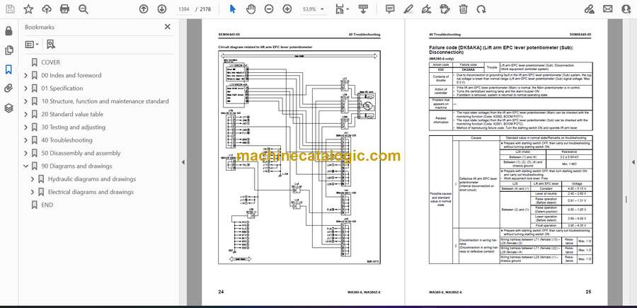
- Failure code [DK5AKA] (Lift arm EPC lever potentiometer (Sub): Disconnection)
- Failure code [DK5AKY] (Lift arm EPC lever potentiometer (Sub): Short circuit with power supply line)
- Failure code [DK5BKA] (Bucket EPC lever potentiometer (Main): Disconnection)
- Failure code [DK5BKY] (Bucket EPC lever potentiometer (Main): Short circuit with power supply line)
- Failure code [DK5BL8] (Bucket EPC lever potentiometer (Main): Analog signals disagree)
- Failure code [DK5CKA] (Bucket EPC lever potentiometer (Sub): Disconnection)
- Failure code [DK5CKY] (Bucket EPC lever potentiometer (Sub): Short circuit with power supply line)
- Troubleshooting by failure code (Display of code), Part 8
- Failure code [DK5FKA] (Joystick steering EPC lever potentiometer (Main): Disconnection)
- Failure code [DK5FKY] (Joystick steering EPC lever potentiometer (Main): Short circuit with power supply line)
- Failure code [DK5GKA] (Joystick steering EPC lever potentiometer (Sub): Disconnection)
- Failure code [DK5GKY] (Joystick steering EPC lever potentiometer (Sub): Short circuit with power supply line)
- Failure code [DK5FL8] (Joystick steering EPC lever potentiometer (Main): Analog signals disagree)
- Failure code [DKA0KA] (Lift arm angle sensor: Disconnection)
- Failure code [DKA0KX] (Lift arm angle sensor: Out of input signal range)
- Failure code [DKA0KY] (Lift arm angle sensor: Short circuit with power supply line)
- Failure code [DKA0L0] (Lift arm angle sensor: Dislocation of sensor)
- Failure code [DLT3KA] (Transmission output shaft speed sensor: Disconnection)
- Failure code [DLT3LC] (Transmission output shaft speed sensor: Out of input signal range)
- Failure code [DT20KB] (Transmission cut-off indicator lamp: Short circuit)
- Failure code [DUM1KB] (Remote positioner raise set indicator lamp: Short circuit)
- Failure code [DUM2KB] (Remote positioner lower set indicator lamp: Short circuit)
- Failure code [DV00KB] (Alarm buzzer: Short circuit)
- Failure code [DW4PKA] (Lift arm raise EPC solenoid: Disconnection)
- Failure code [DW4PKB] (Lift arm raise EPC solenoid: Short circuit)
- Failure code [DW4PKY] (Lift arm raise EPC solenoid: Short circuit with power supply line)
- Failure code [DW4QKA] (Lift arm lower EPC solenoid: Disconnection)
- Failure code [DW4QKB] (Lift arm lower EPC solenoid: Short circuit)
- Failure code [DW4QKY] (Lift arm lower EPC solenoid: Short circuit with power supply line)
- Failure code [DW4RKA] (Bucket tilt EPC solenoid: Disconnection)
- Failure code [DW4RKB] (Bucket tilt EPC solenoid: Short circuit)
- Failure code [DW4RKY] (Bucket tilt EPC solenoid: Short circuit with power supply line)
- Troubleshooting by failure code (Display of code), Part 9
- Failure code [DW4SKA] (Bucket dump EPC solenoid: Disconnection)
- Failure code [DW4SKB] (Bucket dump EPC solenoid: Short circuit)
- Failure code [DW4SKY] (Bucket dump EPC solenoid: Short circuit with power supply line)
- Failure code [DW7BKA] (Fan reverse solenoid: Disconnection)
- Failure code [DW7BKB] (Fan reverse solenoid: Short circuit)
- Failure code [DW7BKY] (Fan reverse solenoid: Short circuit with power supply line)
- Failure code [DWM1KA] (Work equipment neutral lock solenoid: Disconnection)
- Failure code [DWM1KB] (Work equipment neutral lock solenoid: Short circuit)
- Failure code [DWM1KY] (Work equipment neutral lock solenoid: Short circuit with power supply line)
- Failure code [DWN6KA] (Lift arm raise magnet detent solenoid: Disconnection)
- Failure code [DWN6KB] (Lift arm raise magnet detent solenoid: Short circuit)
- Failure code [DWN6KY] (Lift arm raise magnet detent solenoid: Short circuit with power supply line)
- Failure code [DWN7KA] (Lift arm float magnet detent solenoid: Disconnection)
- Failure code [DWN7KB] (Lift arm float magnet detent solenoid: Short circuit)
- Failure code [DWN7KY] (Lift arm float magnet detent solenoid: Short circuit with power supply line)
- Failure code [DWN8KA] (Bucket tilt magnet detent solenoid: Disconnection)
- Failure code [DWN8KB] (Bucket tilt magnet detent solenoid: Short circuit)
- Failure code [DWN8KY] (Bucket tilt magnet detent solenoid: Shorted with the power source)
- Failure code [DX16KA] (Fan pump EPC solenoid: Disconnection) (WA380-6)
- Failure code [DX16KA] (Fan motor EPC solenoid: Disconnection) (WA380Z-6)
- Failure code [DX16KB] (Fan pump EPC solenoid: Short circuit) (WA380-6)
- Failure code [DX16KB] (Fan motor EPC solenoid: Short circuit) (WA380Z-6)
- Failure code [DX16KY] (Fan motor EPC solenoid: Short circuit with power supply line) (WA380Z-6)
- Failure code [DXA1KA] (Loader pump EPC solenoid: Disconnection)
- Failure code [DXA1KB] (Loader pump EPC solenoid: Short circuit)
- Failure code [DXH1KA] (Lockup ECMV solenoid: Disconnection)
- Failure code [DXH1KB] (Lockup ECMV solenoid: Short circuit)
- Failure code [DXH1KY] (Lockup ECMV solenoid: Short circuit with power supply line)
- Failure code [DXH4KA] (1st clutch ECMV solenoid: Disconnection)
- Failure code [DXH4KB] (1st clutch ECMV solenoid: Short circuit)
- Failure code [DXH4KY] (1st clutch ECMV solenoid: Short circuit with power supply line)
- Troubleshooting by failure code (Display of code), Part 10
- Failure code [DXH5KA] (2nd clutch ECMV solenoid: Disconnection)
- Failure code [DXH5KB] (2nd clutch ECMV solenoid: Short circuit)
- Failure code [DXH5KY] (2nd clutch ECMV solenoid: Short circuit with power supply line)
- Failure code [DXH6KA] (3rd clutch ECMV solenoid: Disconnection)
- Failure code [DXH6KB] (3rd clutch ECMV solenoid: Short circuit)
- Failure code [DXH6KY] (3rd clutch ECMV solenoid: Short circuit with power supply line)
- Failure code [DXH7KA] (R clutch ECMV solenoid: Disconnection)
- Failure code [DXH7KB] (R clutch ECMV solenoid: Short circuit)
- Failure code [DXH7KY] (R clutch ECMV solenoid: Short circuit with power supply line)
- Failure code [DXH8KA] (F clutch ECMV solenoid: Disconnection)
- Failure code [DXH8KB] (F clutch ECMV solenoid: Short circuit)
- Failure code [DXH8KY] (F clutch ECMV solenoid: Short circuit with power supply line)
- Failure code [DXHHKA] (4th clutch ECMV solenoid: Disconnection)
- Failure code [DXHHKB] (4th clutch ECMV solenoid: Short circuit)
- Failure code [DXHHKY] (4th clutch ECMV solenoid: Short circuit with power supply line)
- Failure code [DXHLKA] (Joystick steering right EPC solenoid: Disconnection)
- Failure code [DXHLKB] (Joystick steering right EPC solenoid: Short circuit)
- Failure code [DXHLKY] (Joystick steering right EPC solenoid: Short circuit with power supply line)
- Failure code [DXHMKA] (Joystick steering left EPC solenoid: Disconnection)
- Failure code [DXHMKB] (Joystick steering left EPC solenoid: Short circuit)
- Failure code [DXHMKY] (Joystick steering left EPC solenoid: Short circuit with power supply line)
- Failure code [DY30MA] Motor-driven emergency steering pump failure (During operation of machine)
- Failure code [DY30MC] Motor-driven emergency steering pump failure (Malfunction in manual mode)
- Troubleshooting of electrical system (E-mode)
- Installing positions of fuses
- Information in troubleshooting table
- E-1 Engine does not start
- E-2 Wiper does not operate
- E-3 Windshield washer does not operate
- E-4 Headlamp, clearance lamp, tail lamp, and license lamp do not light up or go off
- E-5 Working lamp does not light up or go off
- E-6 Turn signal lamp and hazard lamp do not light up or go off
- E-7 Brake lamp does not light or it keeps lighting up
- E-8 Backup lamp does not light or it keeps lighting up
- E-9 Backup buzzer does not sound or it keeps sounding
- E-10 Horn does not sound or it keeps sounding
- E-11 Alarm buzzer does not sound or it keeps sounding
- E-12 Air conditioner does not operate or stop
- E-13 The KOMTRAX system does not work properly
- E-14 When kick-down switch is turned ON, kick-down operation does not start
- E-15 When hold switch is pressed, holding operation does not start
- E-16 Transmission is kept in neutral, or brake drags when directional lever is operated while parking brake is applied
- E-17 Transmission cut-off mode cannot be set or reset
- E-18 Transmission cut-off set cannot be reset
- E-19 FNR switch mode cannot be set or reset
- E-20 Fan reverse function cannot be used or reset
- E-21 Discharge from loader pump does not rise from minimum level
- E-22 ECSS function cannot be used or reset
- E-23 When parking brake is turned ON, parking brake indicator lamp does not light up
- E-24 When emergency brake operates, brake oil pressure caution lamp does not operate
- E-25 Air cleaner clogging indicator lamp does not light up
- E-26 Radiator coolant level caution lamp does not light up
- E-27 Hydraulic oil temperature gauge does not rise and hydraulic oil temperature caution lamp does not light up
- E-28 Torque converter oil temperature gauge does not rise and torque converter oil temperature caution lamp does not light up
- E-29 Steering oil pressure caution lamp does not light up
- E-30 Abnormality in ■ switch (panel switch 1) input
- E-31 Abnormality in <> switch (panel switch 2) input
- 名称未設定
- E-32 Abnormality in < switch (panel switch 3) input
- E-33 Abnormality in > switch (panel switch 4) input
- Troubleshooting of hydraulic and mechanical system (H-mode)
- Method of using troubleshooting chart
- Table of failure modes and causes
- H-1 The machine does not start
- H-2 Torque converter lockup is not switched off (engine stalls) [Machine with lockup clutch]
- H-3 Torque converter lockup is not switched on [Machine with lockup clutch]
- H-4 The travel speed is slow, the thrusting force is weak, the uphill traveling power is weak, and the gear is not shifted
- H-5 Shocks are large at the times of starting and shifting gear
- H-6 Time lag is large at the times of starting and shifting gear
- H-7 The torque converter oil temperature is high
- H-8 Steering does not turn
- H-9 Steering does not turn [Machine with joystick steering]
- H-10 Steering response is low
- H-11 Turning, response of steering is poor [machine with joystick steering]
- H-12 Steering is heavy
- H-13 When machine turns, it shakes or makes large shocks
- H-14 When machine turns, it shakes or makes large shocks [machine with joystick steering]
- H-15 The wheel brake does not work or does not work well
- H-16 The wheel brake is not released or it drags
- H-17 The parking brake does not work or does not work well
- H-18 The parking brake is not released or it drags (including emergency release system)
- H-19 When brake pedal is pushed, unusual noise or vibration occurs from around pedal
- H-20 Lift arm does not rise
- H-21 Lift arm speed is low or rising force of lift arm is insufficient
- H-22 When rising, the lift arm comes to move slowly at specific height
- H-23 The lift arm cylinder cannot hold down the bucket (Bucket floats)
- H-24 Hydraulic drifts of the lift arm is large
- H-25 The lift arm wobbles during operation
- H-26 Bucket does not tilt back
- H-27 Bucket speed is low or tilting back force is insufficient
- H-28 The bucket comes to operate slowly in the midst of tilting-back
- H-29 The bucket cylinder cannot hold down the bucket
- H-30 Hydraulic drifts of the bucket is large
- H-31 The bucket wobbles during travel with cargo (The work equipment valve is set to “HOLD”)
- H-32 Lift arm and bucket control levers do not move smoothly and are heavy
- H-33 During operation of the machine, engine speed lowers remarkably or engine stalls
- H-34 Large shock is made when work equipment starts and stops
- H-35 When work equipment circuit is relieved singly, other work equipment moves
- H-36 ECSS does not operate, and pitching, bouncing occur
- H-37 Fan revolution is abnormal (Fan sound/ vibration is abnormally large or engine overheats)
- Troubleshooting of engine (S-mode)
- Method of using troubleshooting charts
- S-1 Engine does not start easily
- S-2 Engine does not start
- S-3 Engine does not pick up smoothly
- S-4 Engine stops during operations
- S-5 Engine does not rotate smoothly
- S-6 Engine lacks output (or lacks power)
- S-7 Exhaust smoke is black (Incomplete combustion)
- S-8 Oil consumption is excessive (or exhaust smoke is blue)
- S-9 Engine oil becomes contaminated quickly
- S-10 Fuel consumption is excessive
- S-11 Coolant contains oil (blows back or reduces)
- S-12 Oil pressure drops
- S-13 Oil level rises (Water, fuel in oil)
- S-14 Coolant temperature rises too high (Overheating)
- S-15 Abnormal noise is made
- S-16 Vibration is excessive
- 50 Disassembly and assembly
- General information on disassembly and assembly
- Precautions before work
- How to read this manual
- Coating materials list
- Special tools list
- Sketches of special tools
- Engine and cooling system
- Removal and installation of fuel supply pump assembly
- Removal and installation of fuel injector assembly
- Removal and installation of cylinder head assembly
- Removal and installation of engine hood assembly
- Removal and installation of radiator assembly
- Removal and installation of air aftercooler
- Power train
- Removal and installation of torque converter and transmission assembly
- Disassembly and assembly of torque converter assembly (Standard specification)
- Disassembly and assembly of torque converter assembly (Lockup specification)
- Disassembly and assembly of transmission assembly
- Disassembly and assembly of transmission clutch pack assembly
- Disassembly and assembly of parking brake assembly
- Removal and installation of front axle assembly
- Removal and installation of rear axle assembly
- Disassembly and assembly of axle housing
- Disassembly and assembly of differential assembly
- Steering system
- Removal and installation of steering valve assembly
- Removal and installation of steering valve oil seal
- Brake system
- Removal and installation of parking brake discs and plates
- Undercarriage and frame
- Removal and installation of center hinge pin
- Removal and installation of counterweight
- Hydraulic system
- Removal and installation of work equipment control valve assembly
- Removal and installation of power train pump and work equipment pump assembly
- Removal and installation of steering pump and cooling fan pump assembly
- Removal and installation of hydraulic tank assembly
- Work equipment
- Removal and installation of work equipment assembly
- Disassembly and assembly of hydraulic cylinder assembly
- Cab and its attachments
- Removal and installation of operator's cab and floor frame assembly
- Removal and installation of operator's cab glass (stuck glass)
- Disassembly and assembly of operator's seat assembly (Standard specification)
- Disassembly and assembly of operator's seat assembly (Manufactured by GRAMMER)
- Removal and installation of air conditioner unit assembly
- Electrical system
- Removal and installation of engine controller assembly
- 90 Diagrams and drawings
- Hydraulic diagrams and drawings
- Power train hydraulic circuit diagram
- Automatic greasing circuit diagram
- Hydraulic circuit diagram (WA380-6)
- Hydraulic circuit diagram (WA380Z-6)
- Electrical diagrams and drawings
- Electrical circuit diagram
- Work equipment controller system electrical circuit diagram
- Connector list and stereogram
- END
Komatsu


