Format: PDF (Printable Document)
File Language: English
File Pages: 271
File Size: 34.50 MB (Speed Download Link)
Brand: Liebherr
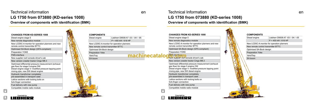
Model: LG 1750 Lattice Boom Crane
Components: Carrier + Superstructure
Serial No: SN 073921
Date: 2023
Type of Document: Technical Information & BMK Components Manual
$ 80
The Liebherr LG 1750 Lattice Boom Crane is a serious bit of kit, and when it throws an electrical or hydraulic fault, the first headache is usually: “Where on this crane is that thing?” The Technical Information & BMK Components Manual for the Liebherr LG 1750 (SN 073921) is what techs grab when they’ve got a code or schematic tag but no idea where the component actually sits. In a workshop, clear component identification is what saves you hours of hunting around the carrier and superstructure. That’s time and money you’re not billing or you’re eating.
What this manual helps you do
Who this is for
This suits a workshop technician, field service tech, electrical diagnostic engineer, fleet mechanic, or training instructor who already has service info or schematics. If you’re after repair steps, torque specs, or part numbers, you need a service manual or parts catalogue instead, not this BMK.
FAQ
Q: Is the PDF clear and searchable enough to zoom in on diagrams?
A: Yes, it’s a PDF with readable component diagrams you can zoom on for practical workshop use.
Q: Does it cover just the upper crane or the whole machine?
A: This BMK manual covers both the carrier and the superstructure together for the LG 1750.
Q: Does it work alongside other Liebherr manuals?
A: Yes, the BMK component identification ties directly into Liebherr wiring diagrams, service manuals, and parts catalogues by using the same reference designators.
Bottom line: If your main need is to find and identify components on the Liebherr LG 1750 by their BMK codes, this is the right manual. If you want repair procedures or parts lists, it’s not what you’re after.
Chassis………………………………………………………………………………..4
Lighting front and mirrors…………………………………………………………4
Lighting rear…………………………………………………………………………..5
Lighting rear, back-up camera………………………………………………….6
Support control unit, side marker lights left…………………………………7
Support control unit, side marker lights right………………………………8
► Driver cab…………………………………………………………………………….9
Doors and windows, interior lighting, radio…………………………………9
Screen wipers, heating………………………………………………………….10
Fan heat exchanger, servo drive fresh air……………………………….. 11
Control elements…………………………………………………………………..12
Batteries………………………………………………………………………………13
Centre console – I/O- modules, custom circuit module……………….14
Centre console – diagnosis plug, earth distributor……………………..15
Centre console – fuses…………………………………………………………..16
Centre console – relay……………………………………………………………17
Centre console – Relays, voltage converter………………………………18
Air-conditioner………………………………………………………………………19
► Pneumatic system………………………………………………………………20
Pressure sensor driver cab…………………………………………………….20
Air dryer, compressor…………………………………………………………….21
Brake force reduction…………………………………………………………….22
Air reservoir mounting……………………………………………………………23
Brake relay- / overload protection valve…………………………………..24
► Drive assembly…………………………………………………………………..25
D9508 A7 -03 (eAGR) / -04 (SCRonly) / -05 (SCRF)………………..25
Plug connection diesel engine………………………………………………..25
Overview V-area and preheating diesel engine filter………………….26
Engine control unit………………………………………………………………..27
Injectors LCR-I S2………………………………………………………………..28
Type plates………………………………………………………………………….28
Fuel low pressure sensors……………………………………………………..29
Fuel pumps………………………………………………………………………….30
Charge air preheating and sensors…………………………………………31
Exhaust gas turbo charger with wastegate……………………………….32
Coolant- temperature sensor………………………………………………….33
Overview fly-wheel side…………………………………………………………34
Speed-and camshaft sensor…………………………………………………..35
Starter and generator…………………………………………………………….36
Overview fan side…………………………………………………………………37
LIEBHERR-oil module with oil pressure sensor………………………..38
Oil level and temperature sensor…………………………………………….39
Exhaust gas flap…………………………………………………………………..40
Diesel engine D9508 A7 -03 (eAGR) / Powerband H………………41
External exhaust gas return eAGR………………………………………….41
Intercooler temperature sensor……………………………………………….42
Copyright by
liebherr
LWE – Customer Service – Documentation
Author: lwebef1 / Issue: 13.07.2020
LG 1750 from 073880 (KD-series 1008) UW-02 • BMK – Overview of components 2 of 113
► Exhaust after treatment SCR……………………………………………….43
Urea tank and tank sensor……………………………………………………..43
Pump module and AdBlue-lines………………………………………………44
Exhaust after treatment -04 (SCRonly)…………………………………45
Overview exhaust after treatment SCR stage IV……………………….45
sensors……………………………………………………………………………….46
Exhaust after treatment -05 (SCRF)……………………………………..47
Overview exhaust after treatment SCRF stage V………………………47
AdBlue-injector and upstream-sensors…………………………………….48
Downstream-sensors, differential pressure………………………………49
► Diesel fuel system………………………………………………………………50
Fuel pump and -tank……………………………………………………………..50
prefilter unit………………………………………………………………………….51
► Air filter system…………………………………………………………………..52
Air filter vacuum, coolant level………………………………………………..52
► Cooling system…………………………………………………………………..53
Overview……………………………………………………………………………..53
Cooling water level, Return fan……………………………………………….54
► Automated shift gearbox 12 TC 3041 SO……………………………..55
Overview of components……………………………………………………….55
Overview electric………………………………………………………………….56
Torque converter…………………………………………………………………..57
Gearbox governor, clutch actuator…………………………………………..58
Intarder……………………………………………………………………………….59
► Hydraulic supply…………………………………………………………………60
Overview hydraulic pumps……………………………………………………..60
Temperature sensor hydraulic oil, hydraulic oil tank…………………..61
► Drive train…………………………………………………………………………..62
Distribution gearbox W3751 P TO SPF……………………………………62
Differential locks – axle 2 and 4 (drive 14 x 6)……………………………63
Differential locks – axle 4 and 6 (drive 14 x 6)……………………………64
Differential locks, engine brake……………………………………………….65
Eddy current brake Telma FOCAL 2200L 24 V………………………….66
► Steering……………………………………………………………………………..67
Switching over pressure stage, deficiency monitoring………………..67
Steering gear, flow control valve emergency steering pump………68
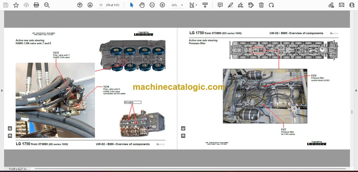
► Active rear axle steering……………………………………………………..69
Angle sensor………………………………………………………………………..69
Resistor modules in the outrigger boxes………………………………….70
Switching over pressure stage, pretensioning centering circuit……71
Valve block axle 5 and 6………………………………………………………..72
Valve block axle 7 and 8………………………………………………………..73
HAWE-VAN-valve axle 5 and 6……………………………………………….74
HAWE-CAN-valve axle 7 and 8………………………………………………75
Pressure filter……………………………………………………………………….76
Emergency supply centering, flow display………………………………..77
► Support………………………………………………………………………………78
Pressure supply, oil release……………………………………………………78
Pressure stages……………………………………………………………………79
Support valves, pinning sliding beams – left……………………………..80
Support valves, pinning sliding beams – right……………………………81
Pinning sliding beam……………………………………………………………..82
Slewing cylinder sliding beam…………………………………………………83
Slewing cylinder sliding beam…………………………………………………84
Pressure sensor for support force display left…………………………..85
Pressure sensor for support force display right…………………………86
Folding outrigger-monitoring…………………………………………………..87
Sliding beam monitoring with rope length sensor………………………88
Inclination sensor………………………………………………………………….89
Sockets for remote control panel left……………………………………….91
Sockets for remote control panel right……………………………………..92
► Axle suspension…………………………………………………………………93
Pressure supply, oil release……………………………………………………93
Axle compensation, blocked/sprung, switching over bladder accumulator…..94
Valves for axle compensation left……………………………………………95
Valves for axle compensation right………………………………………….96
Filling- and drain valves left front…………………………………………….97
Filling- and drain valves left rear……………………………………………..98
Filling- and drain valves right front…………………………………………..99
Filling- and drain valves right rear………………………………………….100
Axle 3 – 6 right…………………………………………………………………….101
Axle 3 – 6 left………………………………………………………………………102
Level sensor- axle suspension……………………………………………..103
Level sensor- axle suspension……………………………………………..104
► Other………………………………………………………………………………..105
Rotary connection……………………………………………………………….105
► Special equipment…………………………………………………………….106
Additional heating……………………………………………………………….106
External power supply…………………………………………………………107
Battery charger…………………………………………………………………..108
Emergency stop………………………………………………………………….109
► Index………………………………………………………………………………..110
Cab………………………………………………………………………………………4
Control stand……………………………………………………………………….4
LICCON monitors and pedals…………………………………………………..4
Joystick 1 and 2……………………………………………………………………..5
Operation- and control unit LSB BKE-B……………………………………..6
Control elements side console………………………………………………….7
Control elements side console………………………………………………….8
Work planner on BSE……………………………………………………………..9
Cab installation:………………………………………………………………….10
Radio and interior lighting………………………………………………………10
Roof console……………………………………………………………………….. 11
Lighting, antenna………………………………………………………………….12
Voltage converter………………………………………………………………….13
Wipe- and washer…………………………………………………………………14
Tilting cab, emergency stop, hooter…………………………………………15
Cab slewing, mirror heating……………………………………………………16
Camera monitoring……………………………………………………………….17
LMB warning device……………………………………………………………..18
Access……………………………………………………………………………….19
Actuation……………………………………………………………………………..19
Emergency lowering……………………………………………………………..20
Ladder up…………………………………………………………………………….21
Heating and cooling……………………………………………………………22
Heating air conditioning…………………………………………………………22
Additional heating Thermo Pro 90…………………………………………..23
Temperature sensors…………………………………………………………….24
Switch cabinet cab (+S400)………………………………………………….26
Plug connections, fuses…………………………………………………………26
Mobile radio module, relay, emergency stop…………………………….27
Clamping strip, assembly parts……………………………………………….28
► Electric slewing platform…………………………………………………….29
Battery box…………………………………………………………………………..29
Sockets, pinning slewing platform…………………………………………..30
Switch cabinet slewing platform………………………………………….31
Plug-in connections to switch cabinet +S400, external supply…….31
Power supply (NT) and central units (ZE)…………………………………32
Input boards (EP), FMS-interface……………………………………………33
BTB, IO-module 6, relay………………………………………………………..34
Relays…………………………………………………………………………………35
Assembly parts, clamps…………………………………………………………36
Fuses, plug plate………………………………………………………………….37
Emergency operation – plug……………………………………………………38
Emergency operation – line resistors……………………………………….39
Central greasing device………………………………………………………40
Electric pump……………………………………………………………………….40
Grease distributor…………………………………………………………………41
Copyright by
liebherr
LWE – Customer Service – Documentation
Author: lwebef1 / Issue:01.06.23
LG 1750 from 073880 (KD-series 1008) OW-02 • BMK – Overview of components 2 of 150
► Drive assembly…………………………………………………………………..42
Overview with SCRF-device (stage 5)……………………………………..42
Cooling system…………………………………………………………………….43
Overview emission indexes……………………………………………………44
Diesel engine D9508 A7 (for Ekz -00; -03; -04; -50; -05)…………45
Overview V-area…………………………………………………………………..45
Ambient temperature…………………………………………………………….46
Engine control unit
ECU2………………………………………………………………………………….47
Overview fuel system…………………………………………………………….48
Injectors LCR-I S2………………………………………………………………..49
Type plates………………………………………………………………………….49
Fuel low pressure sensors……………………………………………………..50
Fuel pumps………………………………………………………………………….51
Charge air preheating and -sensors………………………………………..52
Exhaust gas turbo charger with wastegate……………………………….53
Coolant- temperature sensor………………………………………………….54
Electrical coolant preheating…………………………………………………..55
Overview fly-wheel side…………………………………………………………56
Speed-and camshaft sensor…………………………………………………..57
Parallel starter installation………………………………………………………58
Generator…………………………………………………………………………….58
Overview fan side…………………………………………………………………59
Liebherr-oil module with oil pressure sensor…………………………….60
Oil level- and -temperature sensor………………………………………….61
Exhaust gas flap…………………………………………………………………..62
Sensors in air intake……………………………………………………………..63
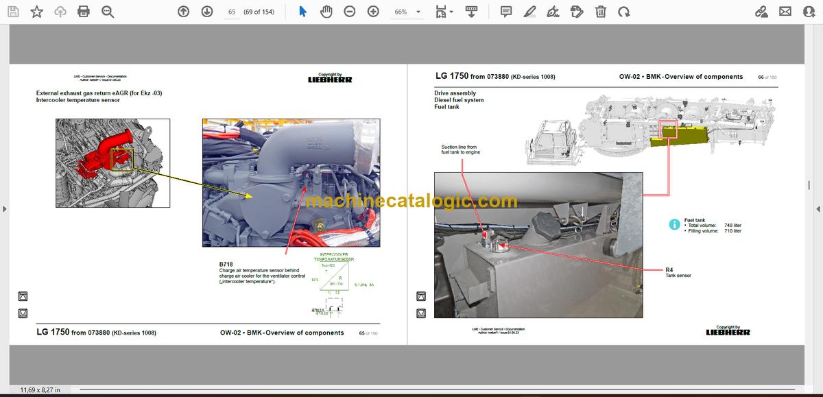
External exhaust gas return eAGR (for Ekz -03)……………………64
AGR-flap……………………………………………………………………………..64
Intercooler temperature sensor……………………………………………….65
Diesel fuel system………………………………………………………………66
Fuel tank……………………………………………………………………………..66
Fuel prefilter unit…………………………………………………………………..67
► Exhaust after treatment (Ekz -04, -05, -50)……………………………68
Overview……………………………………………………………………………..68
AdBlue tank…………………………………………………………………………69
AdBlue tank gauge unit (extraction module)……………………………..70
AdBlue lines…………………………………………………………………………71
SCR-pump module……………………………………………………………….72
AdBlue-injector…………………………………………………………………….73
Compressed air supply………………………………………………………….74
Heating tank and pump………………………………………………………….75
Exhaust gas temperature sensor (Ekz -04, -05, -50)………………….76
NOx-sensor upstream and downstream (Ekz -04, -05, -50)………..77
Exhaust after treatment (Ekz -04, -50)…………………………………..78
Overview……………………………………………………………………………..78
Downstream sensors for EKZ -04 and -50……………………………….79
Upstream sensors for EKZ -04 and -50……………………………………80
Exhaust after treatment (Ekz -05)…………………………………………81
Installation place exhaust gas sensors for Ekz -05…………………….81
NH3 (ammonia)-sensor (Ekz -05)……………………………………………82
Differential pressure sensor (Ekz -05)……………………………………..83
► Pneumatic system………………………………………………………………84
Airdrier and compressor………………………………………………………..84
Shut off flaps in suction air……………………………………………………..85
► Hydraulic slewing platform………………………………………………….86
Overview – allocation of functions to pumps……………………………..86
Overview pumps from slewing platform top………………………………87
Overview pumps from underside slewing platform…………………….88
Pump 1, pump 2, pump 5 and pump 6…………………………………….89
Pump 3 and pump 4……………………………………………………………..90
Pump – pressure control………………………………………………………..91
Pressure sensors pumps……………………………………………………….92
Pump 4 – change-over winch 4 / winch 6………………………………….93
Auxiliary winch, slewing cabin………………………………………………..94
Locking slewing platform……………………………………………………….95
Activation Derrick………………………………………………………………….96
Activation S and L…………………………………………………………………97
Slewing gear……………………………………………………………………….98
Brake, free-wheel………………………………………………………………….98
Brake, speed, incremental sensor…………………………………………..99
S- or L- base section…………………………………………………………100
Pinning S- or L base section…………………………………………………100
SA-frame and Derrick………………………………………………………..101
Mounting and dismantling SA – frame…………………………………….101
Pin connection SA frame and derrick – control…………………………102
Pin connection SA frame and derrick – pin pulling device………….103
Pulley set SA – frame…………………………………………………………..104
Winches……………………………………………………………………………105
Winch 1 (hoist rope )……………………………………………………………105
Winch 2 (hoist rope)…………………………………………………………….106
Winch 3 (S variation winch)………………………………………………….107
Winch 4 (variation winch)……………………………………………………..108
Winch 5 (variation rope or hoist rope – customer‘s spec.)…………109
Winch 6 (2-hook mode with boom nose)……………………………….. 110
► Boom……………………………………………………………………………….. 111
S-boom – base section………………………………………………………… 111
S boom – head section………………………………………………………… 112
Fall back cylinder for S-boom and derrick……………………………… 113
Derrick-base section…………………………………………………………… 114
W-assembly unit………………………………………………………………… 115
W-assembly unit………………………………………………………………… 116
Plug-in connections booms………………………………………………….. 117
Inclination sensor hook block……………………………………………….. 118
F2-connecting head……………………………………………………………. 119
Load cell…………………………………………………………………………..120
Load cell 1 on SA-frame………………………………………………………120
Load cell 2 on luffing jib……………………………………………………….121
Load cell 3 on S-boom – head section……………………………………122
Load cell on the F2 connesting head……………………………………..123
Head section…………………………………………………………………….124
F-head section 147 t (916981408)…………………………………………124
F-head section 150 t 7 m (918474308) – F2-system…………………125
F-head section 62 t 13 m (918474308) – F3-system…………………127
L-head section 400 t (916980308)…………………………………………128
Boom nose……………………………………………………………………….129
Boom nose 1 60 t (SL, W, WV) 916981008…………………………….129
Boom nose 2 (S head section)……………………………………………..130
Boom nose 3 120 t (L-head section) 916981108……………………..131
SLGS-Winch (Yoke-operation)……………………………………………132
Overview……………………………………………………………………………132
Yoke-winch 5………………………………………………………………………133
► Suspended ballast VarioTray……………………………………………..134
Activation…………………………………………………………………………..134
Components for the erection………………………………………………..135
Ballast pallet large………………………………………………………………136
Ballast pallet small………………………………………………………………137
Pressure sensor………………………………………………………………….138
Ballast configuration……………………………………………………………139
Plug of in connection – length sensors for suspended ballast 15 – 20m..140
Plug of in connection – length sensor for suspended ballast 13 – 18m….141
► Slewing platform extension……………………………………………….142
► Accessories………………………………………………………………………143
Hydraulic aggregate – trailer…………………………………………………143
Crawler tractor Merlo Cingo M 8.3 EVO_G…………………………….145
► Haftungsbegrenzung / Disclaimer………………………………………146


