The Liebherr LR 1350-1 Crawler Crane is a heavy lifter that spends its life on plant shutdowns, wind jobs, and big infrastructure work. When something electrical or hydraulic acts up, the first person grabbing a BMK manual is usually the tech with a multimeter in one hand and a fault code in the other. Component identification is what keeps you from wasting half a shift hunting for “K15” or “V23” somewhere on 100+ tons of steel. This Technical Information & BMK Components Manual for SN 074156 is built exactly for that job, not for actual repair steps.
What this manual helps you do
- Identify which physical component matches a schematic tag like E1, K3, V12, X45 on the LR 1350-1.
- Locate sensors, valves, relays, and control units on both the carrier and superstructure using outline and layout views.
- Trace wiring or hydraulic references from Liebherr diagrams to their real mounting positions on the crane.
- Cross-reference component IDs to the right sections in your wiring diagrams, service info, or other Liebherr documents.
- Pinpoint what Liebherr actually calls a given box, valve, or plug so you can talk the same language as the manuals and the dealer.
Who this is for
This is for workshop technicians, field service techs, electrical diagnostic engineers, fleet mechanics, and training instructors. If you need step‑by‑step repair procedures, torque values, or part numbers, you want the service manual and parts catalogue instead, not this BMK.
FAQ
Q: Is the PDF clear and searchable enough to use on a laptop or tablet?
A: Yes, these BMK PDFs are usually clean scans or native files, so diagrams and ID labels are readable and you can search text.
Q: Does it cover both the carrier and the upper crane body?
A: Yes, this Technical Information & BMK Components Manual combines carrier and superstructure layouts for the LR 1350-1.
Q: Does it tie in with other Liebherr documents I already have?
A: Yes, the BMK is meant to be used alongside wiring diagrams, hydraulic schematics, service manuals, and parts catalogues by matching the same reference designators.
Bottom line: if your main problem is “Where is this component on the LR 1350-1, and what does Liebherr call it?”, this is exactly the right manual. If you’re looking for how to fix it or which part number to order, this is not what you need.
📘 Show Index
Table of Contents:
Carrier — Table of Contents
- Raupenträger
- Elektrik
- Verbolzung Raupenträger
- Hydraulik- und Elektroverbindung zum Mittelteil
- Fahrantrieb Sensorik
- Fahrantrieb
- Kettenspanner
- Mittelteil
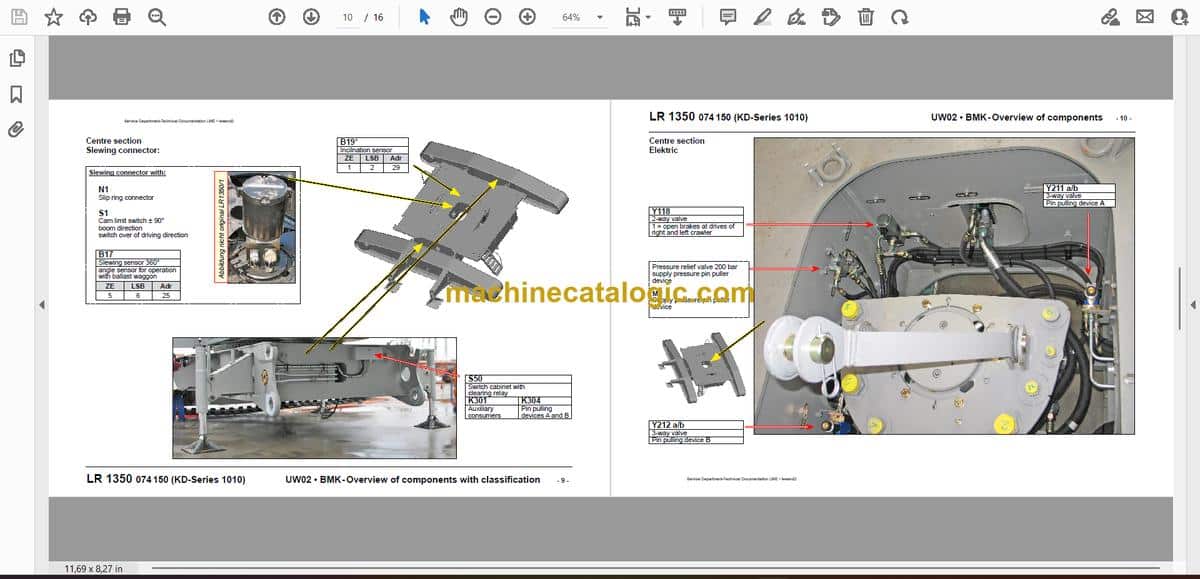
- Drehdurchführung:
- Elektrik
- Übersicht
- Hydraulische Montage-Abstützung
- Index
- Leere Seite
Superstructure — Table of Contents
- LR 1350/1 LN Drehbühne
ab 074150 (KD-Serie 010) Motor D936 A7 SCR
- Übersicht:
- Kabine:
- Steuerstand:
- Monitore, Pedale
- Meisterschalter 1 rechts
- Meisterschalter 2 links
- Seitenkonsole – Bedienelemente
- Elemente in Seitenkonsole
- Kameraüberwachung
- Kabineninstallation:
- Radio und 12V-Netz
- Dachkonsole
- Innen- /Außenbeleuchtung
- Wisch- Waschanlage
- Heizung / Klima
- Heiz- und Klima-Gerät
- Bedienelemente
- Klimaanlage
- Klimaanlage-Kompressorantrieb
- Zusatzheizung „Thermo 90 ST“
- Elektrik Drehbühne:
- Batteriekasten
- Sicherungen
- Batterieladegerät
- Fremdeinspeisung
- Steckverbindungen
- Drehbühne – Ausleger
- Drehbühne – Schaltschrank
- Schaltschrank
- Zentraleinheiten
- Eingangsplatinen
- Steckverbindungen auf Eingangsplatinen
- EA-Modul 6, Datenlogger
- Bauteile
- Sicherungen
- Relais
- Notbetrieb
- Verteilerschienen
- GSM-Modul-Ferndiagnose
- Zentralschmieranlage:
- Antriebsaggregat:
- Dieselmotor D936 A7 270 kW / 362 PS:
- Einbauansicht
- Motorsteuergerät und Bussystem
- Übersicht Einspritzseite
- Übersicht Abgasseite
- Übersicht Schwungradseite
- Übersicht Lüfterseite und Generator
- Kühlmittelsystem
- Kraftstoffsystem
- Liebherr Daisy-Chain Diesel-Einspritzsystem
- Injektoren:
- Kraftstoff-Pumpen
- Drehzahlsensoren
- Ölkreislauf
- Ladeluft-Sensoren und -Vorwärmung
- Ladeluft-Regelung
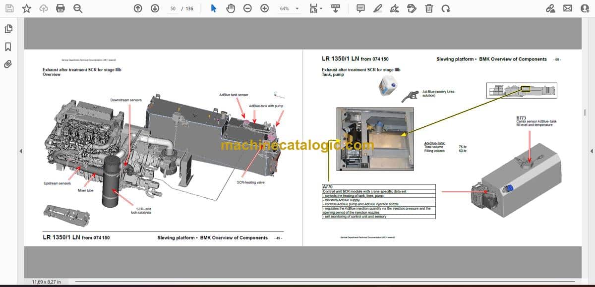
- Abgasnachbehandlung SCR für Stufe IIIb
- Übersicht
- Tank, Pumpe
- Sensorik am Mischrohr (upstream)
- Sensorik am SCR-Kat (downstream)
- Elektrische AdBlue-Leitungs-Heizung
- Heizung SCR
- Dieselkraftstofftank
- Druckluftanlage:
- Kranhydraulik:
- Pumpenverteilergetriebe
- Hydrauliköl-Tank
- Hydrauliköl-Kühler
- Hydraulikpumpen
- Anordnung von Drehbühne oben
- Anordnung von Drehbühne unten
- Einbauansicht von oben
- Einbauansicht von unten
- Beschreibung Pumpen A10VO (ED) Pumpe 7
- Beschreibung Pumpen A10VO (DRG) Pumpe 10, 11
- Beschreibung Pumpen A11VO (DRG); Pumpe 9
- Beschreibung Zahnradpumpe SNP3/90 Pumpe 8
- Beschreibung Pumpen A4VG; Pumpe 1 bis 6
- Drucksensoren
- Speisedruck-Versorgung Pumpe 8
- Hydraulikölvorwärmung über Speisedruck-Pumpe 8
- Pumpen 3 und 4 auf Raupenfahrwerk
- Hydraulik-Notbetrieb
- Einspeisung und Winde 4
- Drehwerk
- Montageplatte Notbetrieb
- Montageplatte Parallelbetrieb
- Nebenverbraucher
- Druckversorgung von Pumpe 9
- Kabine kippen
- Kabine schwenken
- Bolzenziehzylinder S-, L-, D-Anlenkstück
- Montagewinde
- Ballastiereinrichtung-Drehbühnenballast*
- Ballastiereinrichtung-Drehbühnenballast*
- Drehwerk
- Druckversorgung
- Ansteuerung
- Drehwerkantriebe 1 bis 5
- Rückfallzylinder
- Druckversorgung S-, L-, D-Rückfallzylinder
- Ansteuerung S-, L-, D-Rückfallzylinder
- Druckstufen L- / LL-System
- Ansteuerung SA-Bock-Rückfallzylinder
- Winden im Drehbühnenrahmen
- Übersicht
- Getriebenockenendschalter Winde 1 und 2
- Hydraulikanschlüsse Winde 1 und 2
- Winde 1
- Winde 2
- Winde 4
- Versorgung und Anschluss
- Ansteuerung
- Haupt-Ausleger
- S-Anlenkstück
- Elektrik
- Hydraulik
- Winde 5
- Sensoren S-Rückfallzylinder
- S-Adapter
- S-Kopfstück
- „Derrick“-Ausleger D
- Sensorik
- „Derrick“-Anlenkstück-Rückfallzylinder
- Winde 3
- Zugzylinder
- Zugzylinder heben / senken
- Hauptausleger-Aufrichtbock („SA-Bock“)
- Sensorik
- Aufricht- und Rückfallzylinder
- Raupen-Montagevorrichtung („SA-Bock“)
- Montagezylinder
- Ansteuerung
- Kraftmessstellen
- Ballastpalette B
- Wippbare Gitterspitze W
- Übersicht
- W-Anlenkstück
- Auslegerwinkel
- Wippspitze unten
- Klappe
- L-Kopfstück
- WA-Bock 1
- Feste Gitterspitze F
- F-Anschlusskopf und Kopfstück
- Mastnase
- Ballastwagen BW
- Übersicht
- Führungsrohr
- Verbolzung Drehbühne / Ballastwagen
- Hydraulik und Elektrik
- Ansteuerung Ausschiebezylinder
- Abstützung-Ballastwagen
- Radsatz
- Ansteuerung Radeinschlag
- Antrieb und Drehgeber
- Elektrik-Ballastwagen
- Schaltschrank
- Schaltschrank
- Schaltschrank
- Bedienpulte S10, S20 und S30
- Schmieranlage und Neigungsgeber
- Index
Liebherr Crane


