Format: PDF (Printable Document)
File Language: English
File Pages: 143
File Size: 24.42 MB (Speed Download Link)
Brand: Liebherr
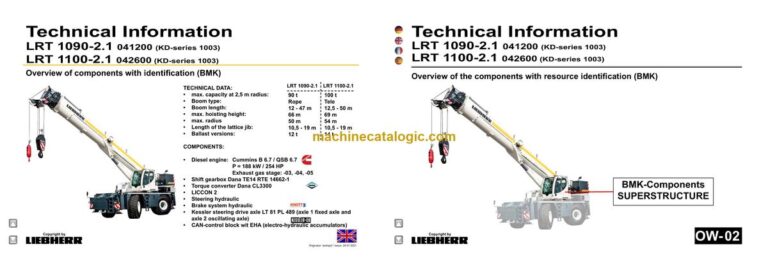
Model: LRT 1090-2.1 Rough Terrain Crane
Components: Carrier + Superstructure
Serial No: SN 041200
Date: 2023
Type of Document: Technical Information & BMK Components Manual
$ 80
The Liebherr LRT 1090-2.1 Rough Terrain Crane spends its life in rough yards and job sites where fast, accurate fault-finding matters. When something’s not behaving, the first person who reaches for a BMK component identification manual is usually the tech with a laptop and wiring diagram in front of them. Component identification is what stops you wasting an hour opening the wrong covers or chasing the wrong valve block. This Technical Information & BMK Components Manual for SN 041200 is built for exactly that: knowing what’s where on the carrier and the superstructure.
What this manual helps you do
Who this is for
This is aimed at workshop technicians, field service techs, electrical diagnostic engineers, fleet mechanics, and training instructors. If you need step‑by‑step repair procedures, torque data, or orderable part numbers, you want the service manual and parts catalogue instead, not this BMK.
FAQ
Q: Are the diagrams clear and searchable in the PDF?
A: Yes, this kind of BMK PDF is designed so you can zoom in on component layouts and search for reference designators or keywords.
Q: Does it cover both the carrier and the superstructure?
A: Yes, it combines BMK component identification for the lower carrier and the upper crane superstructure in one Technical Information document.
Q: Does it tie in with other Liebherr documentation?
A: Yes, the BMK layout and reference designators are meant to be used alongside Liebherr wiring diagrams, hydraulic schematics, service manuals, and parts catalogues.
Bottom line: If your main problem is “Where exactly is this component on the crane?” then yes, this is the right manual. If you’re after how to fix it or what part number to order, then no, this isn’t what you need.
Chassis:……………………………………………………………………………….4
View from front, lighting…………………………………………………………….4
View from rear, lighting……………………………………………………………..5
Lighting support, EMERGENCY-STOP……………………………………….6
Battery, main fuse box………………………………………………………………7
I/O- modules, BTB, ECU……………………………………………………………8
Fuses, diagnostics- and emergency operation plug………………………9
Relay, distributor…………………………………………………………………….10
Diagnosis plug………………………………………………………………………. 11
► Diesel engine Cummins:……………………………………………………..12
Installation overview……………………………………………………………….12
Type plate on engine………………………………………………………………13
Overview fan side…………………………………………………………………..14
Overview injection side……………………………………………………………15
Overview exhaust side…………………………………………………………….16
Overview of exhaust side stage IV with eAGR……………………………17
Overview of exhaust side Power Band H w/o AGR……………………..17
Top view………………………………………………………………………………..18
Top view stage IV engine…………………………………………………………19
Top view Power Band H engine………………………………………………..19
Overview fly-wheel side…………………………………………………………..20
Overview fly-wheel side…………………………………………………………..21
Engine Control Module ECM……………………………………………………22
Engine control unit ECM………………………………………………………….23
Engine-CAN…………………………………………………………………………..24
Fuel scheme ( high- and low pressure)……………………………………..25
Common-Rail-System …………………………………………………………….26
Common-Rail-system Power Band H………………………………………..27
Common-Rail-system stage IV…………………………………………………28
Injectors………………………………………………………………………………..29
Injectors………………………………………………………………………………..30
Fuel prefilter…………………………………………………………………………..30
Air sensors…………………………………………………………………………….31
Air-sensors on stage IV devices……………………………………………….32
Air-sensors Power Band H engine…………………………………………….33
Speed sensors……………………………………………………………………….34
Speed sensors……………………………………………………………………….35
Cooling agent…………………………………………………………………………36
Oil circuit……………………………………………………………………………….37
Exhaust gas turbo charger……………………………………………………….38
Exhaust gas turbo charger for stage IV engines…………………………39
Exhaust gas turbo charger for Power Band H engines ……………….40
► Exhaust after treatment SCR……………………………………………….41
Sensor technology on the diesel oxidation catalyst……………………..41
Sensor technology on the SCR-catalyst…………………………………….42
Mixing tube……………………………………………………………………………43
Exhaust after treatment system:……………………………………………….44
Overview……………………………………………………………………………….44
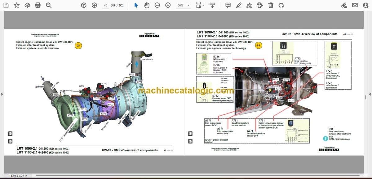
Exhaust system – module overview…………………………………………..45
Exhaust gas system – sensor technology…………………………………..46
AdBlue-pump module……………………………………………………………..47
AdBlue tank and tank gauge unit ……………………………………………..48
Dosing unit AdBlue…………………………………………………………………49
Cooling system:……………………………………………………………………50
Cooler installation…………………………………………………………………..50
Diesel fuel system:……………………………………………………………….51
Fuel prefilter and tank……………………………………………………………..51
► Shift gearbox:……………………………………………………………………..52
Dana TE14 RTE14662-1…………………………………………………………52
► Torque converter:……………………………………………………………….54
Dana CL 3300………………………………………………………………………..54
► Hydraulic:…………………………………………………………………………..55
Temperature sensor hydraulic oil, hydraulic oil tank…………………….55
Pumps – steering, support, axle suspension……………………………….56
Pumps – steering ……………………………………………………………………57
Crane hydraulic – pumps………………………………………………………….58
► Drive train:………………………………………………………………………….59
Overview……………………………………………………………………………….59
► Axle oscillation:………………………………………………………………….60
Oscillating axle……………………………………………………………………….60
Transversal differential lock……………………………………………………..61
► Steering:…………………………………………………………………………….62
Control block (change over block)…………………………………………….62
Switching emergency steering pump, deficiency monitoring, steering gear.
63
Turn sensor……………………………………………………………………………64
Steering cylinder…………………………………………………………………….65
► Brake:…………………………………………………………………………………66
Overview brake system…………………………………………………………..66
Activation………………………………………………………………………………67
Activation………………………………………………………………………………68
► Support:……………………………………………………………………………..69
Inclination sensor, support cylinder…………………………………………..69
Oil supply support…………………………………………………………………..70
Support valves – left………………………………………………………………..71
Support valves – right………………………………………………………………72
Monitoring support pressure with pressure sensor………………………75
Inductive sensor extending support…………………………………………..76
► Special equipment:……………………………………………………………..78
Ballast cylinder……………………………………………………………………….78
Eddy current brake Telma ……………………………………………………….79
Air-conditioner………………………………………………………………………..80
Cooling water preheating ………………………………………………………..81
Additional heating Airtop 2000 STC gearbox / converter ……………..82
Additional heating DBW 2016 ………………………………………………….83
► Index………………………………………………………………………………….84
► Haftungsbegrenzung / Disclaimer………………………………………..
Superstructure general:………………………………………………………..3
Lighting slewing platform / boom………………………………………………..3
LMB warning device (EN 13000)………………………………………………..4
Central greasing device…………………………………………………………….5
Boom direction…………………………………………………………………………6
► Crane cabin:…………………………………………………………………………7
Heating heat exchanger……………………………………………………………7
Heating – activation, temperature sensors……………………………………8
Wiper motors, washer pump, platform…………………………………………9
Interior furnishing……………………………………………………………………10
Controls cab:……………………………………………………………………….11
Liccon – monitor, pedals, ethernet……………………………………………. 11
Joystick right, key board LSB-CAB1………………………………………….12
Joystick left, support control unit LSB-AST3……………………………….13
Operation- and control unit………………………………………………………14
Switch cabinet crane cabin:………………………………………………….15
Fuses……………………………………………………………………………………15
Relay, resistor modules…………………………………………………………..16
Mounting plate – LSB-master, voltage converter…………………………17
Universal in/output module, data logger II………………………………….18
Diagnosis plug, remote diagnosis……………………………………………..19
Plug plate slewing platform / cab………………………………………………20
EMERGENCY OPERATION – XNOT – plug………………………………..21
EMERGENCY OPERATION resistors, air circulation…………………..22
► Crane hydraulic:…………………………………………………………………23
Temperature sensor and oil cooler……………………………………………24
Overview hydraulic components……………………………………………….25
Overview metering connector plate…………………………………………..26
Main control block (Bucher)……………………………………………………..27
Main control block (Bucher)……………………………………………………..28
Hoist gear 1…………………………………………………………………………..29
Hoist gear 2…………………………………………………………………………..30
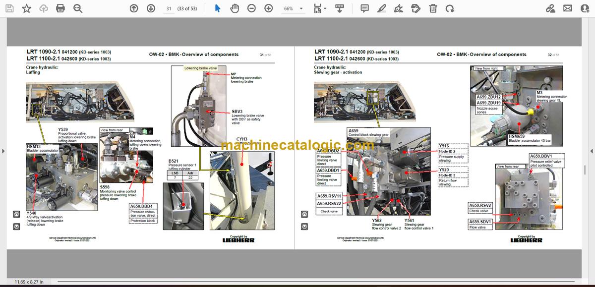
Luffing…………………………………………………………………………………..31
Slewing gear – activation………………………………………………………….32
Slewing gear – brake, locking……………………………………………………33
Auxiliary consumer valves……………………………………………………….34
Cab tilting………………………………………………………………………………35
► Rope boom LRT 1090-2.1:……………………………………………………36
base section, “boom steep”……………………………………………………..36
Boom head……………………………………………………………………………37
Hydraulic……………………………………………………………………………….38
► Telescopic boom LRT 1100-2.1:……………………………………………39
base section, “boom steep”……………………………………………………..39
Boom head……………………………………………………………………………40
Tele section pinning, position sensor…………………………………………41
Cylinder pinning, position sensor………………………………………………42
Hydraulic……………………………………………………………………………….43
► Ballasting……………………………………………………………………………44
► Special equipment:……………………………………………………………..45
Double swing away jib* – electric………………………………………………45
Double swing away jib* + swing away jib slewing……………………….46
Additional heating Airtop 2000ST……………………………………………..47
Camera monitoring (basic set up)……………………………………………..48
Emergency control crane hydraulic*………………………………………….49
► Index………………………………………………………………………………….50


