The Liebherr LTC 1050-3.1E Compact Crane is a tight-access machine that usually shows up where space is expensive and downtime costs real money. When something electrical or hydraulic acts up, the first person reaching for the BMK is usually the tech with a multimeter in one hand and a laptop or tablet in the other. Component identification matters because you don’t have time to guess which “valve block” or “relay box” the schematic is actually talking about. The Technical Information & BMK Components Manual for Liebherr LTC 1050-3.1E Compact Crane provides component identification diagrams, reference designators, and visual outlines used by technicians cross-referencing wiring or hydraulic schematics to physical parts on the crane.
What this manual helps you do
- Identify where a specific component (like “K15” or “V23”) actually sits on the carrier or superstructure.
- Locate electrical boxes, sensors, valves, and control units on the LTC 1050-3.1E using clear outline and layout views.
- Trace reference designators from wiring or hydraulic diagrams to their real-world mounting points on the crane.
- Cross-reference BMK IDs with other Liebherr documents when you’re chasing a fault code or planning a repair.
- Find and match Liebherr’s official component names so you can talk the same language as the parts and service system.
Who this is for
This is aimed at workshop technicians, field service techs, electrical diagnostic engineers, fleet mechanics, and training instructors working on SN 088002 and similar. If you need repair procedures, test steps, or part numbers, you want the service manual and parts catalogue instead, not this BMK.
FAQ
Q: Are the diagrams clear and can I search the file?
A: Yes, this is a readable PDF with clear component layouts that you can zoom and search by text or reference ID.
Q: Does it cover both the carrier and the superstructure?
A: Yes, this BMK combines component identification for the carrier and the superstructure into one manual.
Q: Does it tie in with other Liebherr documentation?
A: Yes, these component IDs are meant to be used alongside Liebherr wiring diagrams, hydraulic schematics, service manuals, and parts catalogues.
Bottom line: if you need to know “where is this exact component on the crane?”, this BMK component identification manual is the right document. If you’re looking for how to fix it or which part number to order, it’s not.
📘 Show Index
Table of Contents:
Carrier — Table of Contents
- Table of contents
- Chassis:
- View from front, lighting and mirror
- View rear, lighting
- Side view left, lighting
- Side view right, lighting
- Warning signal sensors, external start point, plug combination-box
- Electric:
- Battery, main fuse box
- CAN-final resistance
- Ground and distribution plug W6 / W7 / W8
- Ground and distribution plug W6 / W7 / W8
- Switch cabinet chassis:
- Fuses
- I/O- modules, BTB, control unit
- Relays
- Resistors, clamp strip
- Emergency operation- and diagnosis plug, telemetry
- Telemetry modem
- Ventilation and fan in the switch cabinet
- Plug connections
- Pneumatic system:
- Compressor and dryer
- Pressure sensors and valves brake system
- ABV activation valve
- Relay- and overload protection valve
- Adjustment- and relay valve
- Air reservoir mounting
- Valve block aux. consumers
- Monitoring parking brake
- Driving with radio remote control* (RemoteDrive)
- Brake system:
- Overview – monitoring brake pad
- Brake pad monitoring display
- Diesel engine Cummins B6.7 , 243 kW (326 HP):
- Installation overview
- Type plate on engine
- Overview fan side
- Overview injection side
- Overview exhaust gas side
- Top view
- Overview fly-wheel side
- Heating flange
- Engine Control Module ECM
- Fuel scheme ( high- and low pressure)
- Common-Rail-System
- Injectors
- Air sensors
- Speed sensors
- Cooling agent
- Oil circuit
- Exhaust gas turbo charger
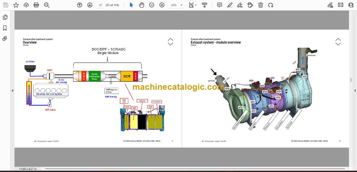
- Exhaust after treatment system:
- Overview
- Exhaust system – module overview
- Exhaust gas system – sensor technology
- AdBlue-pump module
- AdBlue tank and tank gauge unit
- Dosing unit AdBlue
- Fuel tank and fuel filter
- Cooling system:
- Installation overview cooler
- Air filter system:
- Air filter, pressure sensor
- Drive train:
- Overview
- Power shift gearbox- overview ZF 6 WG 210 (level 1)
- Power shift gearbox – sensors
- Power shift gearbox – control and differential
- Distribution gearbox – Kessler W 260
- Electric drive:
- General overview – functional schematic
- General overview – chassis vehicle cabling
- Overview – electric pump drive system (EPAS)
- Current supply – switch for operation modes
- Supply – rectifier
- DC link (direct current)
- DC/DC transformer – vehicle battery
- Generator on diesel engine
- Inverter – electric motor
- Electric motor on distributor gear
- High-voltage control cabinet
- High-voltage control cabinet
- HV control (control system)
- Cooling system installation
- Axles with components:
- ABV – inductive sensors
- Transversal differential locks
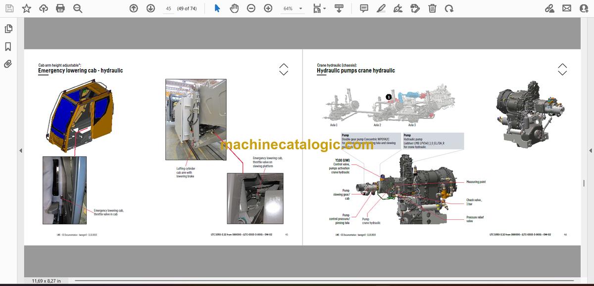
- Hydraulic:
- Hydraulic pumps for steering, fan
- Hydraulic pumps for crane hydraulic, emergency steering
- Hydraulic pump on axle 3
- Crane hydraulic “ON”
- Oil tank
- Steering:
- Steering gear, steering circuit control
- Steering decoupling
- Steering- and centering cylinder
- Active rear axle steering:
- Centering cylinder, emergency supply
- CAN-Valve (HAWE)
- Control block and pressure filter
- Control block, flow rate indicator, check valve
- Monitoring centering circuit
- Angle sensor
- Support:
- Support valves for sliding beams right
- Support valves for sliding beams left
- Inclination sensor
- Sliding beam- hydraulic
- Variable support*:
- Sliding beam monitoring with rope length sensor
- Monitoring support pressure with pressure sensor
- Axle suspension:
- Axle suspensions valve, oil supply
- Valve block axle suspension right
- Valve block axle suspension left
- Axle compensation axle 2
- Level sensor axle suspension
- Special equipment:
- Eddy current brake*
- Back-up camera*
- Battery charger*, external power supply*
- Tire pressure monitoring system*
- Attachment:
- Index
- Limitation of liability / Disclaimer
- Fachbegriffe und Abkürzungen
Superstructure — Table of Contents
- Table of contents
- Superstructure general:
- Lighting slewing platform
- Lighting boom
- LMB – warning device (EN 13000)
- Camera installation
- Immobiliser*, steering element uncoupling
- Central lubrication system
- Ballast – overview
- Ballast – electrically ballast monitoring
- Boom direction
- Crane cabin:
- Climatisation – overview
- Climatisation – additional heating HV
- Climatisation – heating air conditioner
- Climatisation – activation and temperature sensors
- Climatisation – air condition
- Screen washer unit, platform cab, steering angle
- Interior furnishing
- Electric
- Door contact switch
- Pneumatic – brake valve
- Fittings crane cab:
- Control elements (chassis operation)
- Tachograph (chassis operation)
- LICCON-monitor, pedals, ethernet (superstructure operation)
- Master switch, LSB-TE1 right
- Master switch, LSB-TE2 left
- Operation- and control unit
- BTB, remote control module – BTT
- Switch cabinet crane cabin:
- Basis assembly – fuses, remote diagnosis
- Basis assembly – relay, data logger
- Switch cabinet slewing platform:
- Tilting frame – fuses
- Relay, resistor modules
- LSB-board, UEA -/ EA-module, resistors emergency operation
- Emergency control – XNOT plug
- Pneumatic system:
- Cab arm:
- Cab arm lock
- Monitoring cab arm locking – sensor
- Cab arm locking – sensors
- Cab arm luffing – sensors
- Hydraulic – activation, telescoping cylinder
- Hydraulic – telescoping cylinder
- Hydraulic – luffing cylinder
- Cab arm height adjustable*:
- Cab – electric
- Telescope arm – electric
- Cab arm – activation – hydraulic
- Cab arm luffing – hydraulic and sensors
- Emergency lowering cab – hydraulic
- Crane hydraulic (chassis):
- Hydraulic pumps crane hydraulic
- Crane hydraulic “ON”
- Crane hydraulic:
- Overview hydraulic components
- Main control block
- Main control block, metering points
- Slewing gear – hydraulic
- Slewing gear – hydraulic
- Slewing gear – drive, gearbox
- Pretension valve, hydraulic oil preheating
- Luffing cylinder, “boom steep”
- Main hoist gear
- Auxiliary hoist gear*
- Oil cooler*
- Telescoping boom:
- Telematic – bas section
- Telematic – boom head
- Telescoping system Telematic tele- / gripper pinning
- Telescoping system Telematic – gripper position
- Telescoping system Telematic – emergency operation
- Special equipment:
- Swing-away jib*
- Camera – slewing platform, winches*
- Emergency control crane hydraulic*
- Attachment:
- Index
- Limitation of liability / Disclaimer
- Technical terms and abbreviations
Liebherr Crane


