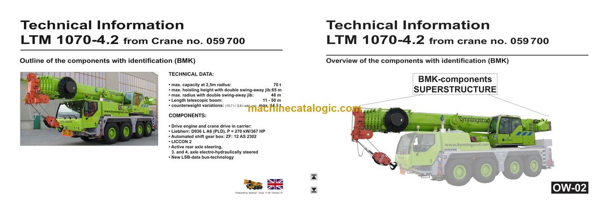
The Liebherr LTM 1070-4.2 Mobile Crane is usually earning money lifting, not sitting dead while you hunt for hidden valves, relays, or sensors. The BMK / component identification manual is what techs grab when the fault code points to “K15” or “V12” and nobody on site knows where that actually lives. In a workshop or on a remote pad with limited tools, fast component ID is what keeps downtime from blowing the schedule. The Technical Information & BMK Components Manual for Liebherr LTM 1070-4.2 Mobile Crane provides component identification diagrams, reference designators, and visual outlines used by technicians cross-referencing wiring or hydraulic schematics to physical parts on the crane.
What this manual helps you do
- Identify which physical component matches a reference like E1, K3, or X45 from Liebherr wiring or hydraulic diagrams.
- Locate relays, sensors, valves, control units, and junction boxes on both carrier and superstructure using layout views.
- Trace harness routes and component groups so you know where to open loom or remove covers before you start tearing in.
- Cross-reference component IDs to other Liebherr documents so your schematics, fault codes, and physical parts all line up.
- Pinpoint crane components during training so new techs learn the machine layout without guessing or trial-and-error.
Who this is for
This is aimed at workshop technicians, field service techs, electrical diagnostic engineers, fleet mechanics, and training instructors. If you need step‑by‑step repair procedures, torque specs, or part numbers, you’re after a service manual or parts catalogue instead, not this BMK.
FAQ
Q: Are the diagrams clear and searchable in PDF form?
A: Yes, this kind of BMK manual is usually supplied as a readable, zoomable PDF with clear component outlines and labels.
Q: Does it cover both the carrier and the upper crane body?
A: Yes, this Technical Information & BMK Components Manual combines carrier and superstructure layout for SN 059962.
Q: Does it tie in with Liebherr wiring diagrams or parts books?
A: Yes, these BMK manuals are designed to match the reference designators used in Liebherr schematics, service information, and parts catalogues.
Bottom line: if you want component identification and locations for the LTM 1070-4.2, this is exactly what you need; if you want how-to repair steps or part numbers, it isn’t.
📘 Show Index
Table of Contents:
Carrier — Table of Contents
- Fahrzeug:
- Ansicht von vorne, Beleuchtung und Spiegel
- Ansicht von hinten, Beleuchtung
- Steckdosen, Warnsignalgeber
- Seitenmarkierungsleuchten rechts
- Seitenmarkierungsleuchten links
- Fahrerhaus:
- Türen und Fenster, Innenbeleuchtung
- Lüftung und Wärmetauscher,
- Scheibenwisch- und waschanlage
- Bedienelemente
- Bluetooth Basiseinheit – BTB Bluetooth Terminal – BTT
- Bedienelemente Mittelkonsole
- Mittelkonsole – E / A- Module, ECU’s
- Mittelkonsole – Batterien, Batteriehauptschalter, Sicherungen Batteriekasten, Spannungswandler
- Mittelkonsole – Sicherungen
- Mittelkonsole – Relais
- Mittelkonsole – Heizflansch-Steuerung
- Mittelkonsole – Diagnosestecker
- NOT-AUS
- Druckluftanlage:
- Kompressor (Luftpresser) und Lufttrockner
- Druckluftvorratbehälter
- Druckgeber und Druckschalter
- Magnetventile Nebenverbraucher
- Scheibenbremsanlage
- Übersicht Bremsbelag Überwachung
- Bremsbelag Überwachungsanzeige
- ABV – Regelventile ABV – Steuerventil
- ABV – Regelventile
- Übersicht Antriebsaggregat
- Dieselmotor D936 L A6 (PLD):
- Übersicht Einspritzseite
- Öldruck und Kraftstofftemperatur
- Kraftstoff-Vorfiltereinheit
- Steckpumpen
- Übersicht Abgasseite
- Lüfterseite und Heizflansch
- Drehzahl-Geber
- Einbauansicht, Motorsteuergerät
- Externe Abgasrückführung (eAGR)
- Ladeluft-Temperatursensoren I und II
- Kühlanlage
- Kühlmittelgeber, Tankgeber
- Automatisiertes Schaltgetriebe:
- ZF 12 AS 2302 (ohne Intarder)
- Hydraulik:
- Temperatursensor Hydrauliköl, Hydraulikölbehälter
- Hydraulikpumpen – Übersicht
- Hydraulikpumpen – Übersicht
- Antriebsstrang:
- Übersicht, Schaltbedingungen
- Verteilergetriebe Kessler VG 2700 (zweistufig)
- Antrieb 8 x 6, Querdifferentialsperren, Zuschaltung Achse 1
- Antrieb 8 x 6 und 8 x 4, Querdifferentialsperren
- ASR, Raddrehzahlsensoren
- Lenkung:
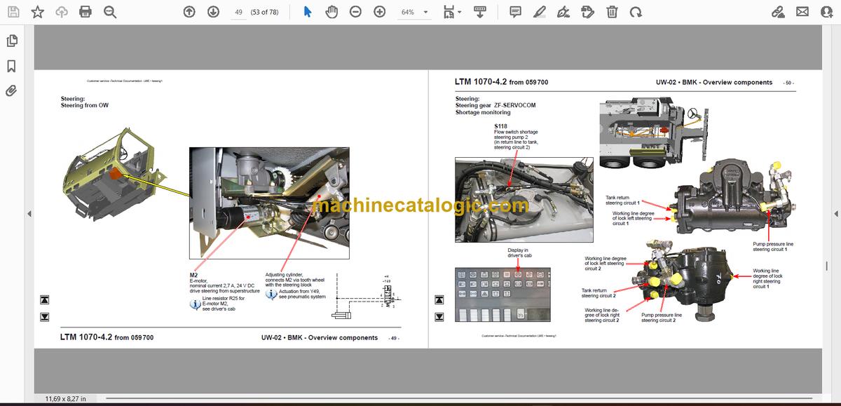
- Lenkung vom Oberwagen aus
- Lenkgetriebe ZF-SERVOCOM Mangelüberwachung
- Mangelüberwachung
- Messanschlüsse MP1 und MP2
- Aktive Hinterachslenkung:
- Bosch-CAN-Ventile Achse 3 und 4
- Ventilblock Achse 3 bis 5
- Messanschlüsse MP6, MP11
- Winkelgeber
- Lenk- und Zentrierzylinder, Sicherheitsventile
- Abstützung
- Neigungsaufnehmer
- Abstützventile – Rechts
- Abstützventile – Links
- Achsfederung:
- Niveaugeber – Achsfederung
- Ventile für Achsdruck-Ausgleich; Blockiert/Gefedert
- Ventilblock – Achsfederung rechts
- Ventilblock – Achsfederung links
- Sonderausstattung:
- Wirbelstrombremse Telma Focal 2200
- Zusatzheizung Thermo ST90
- Klimaanlage
- Druckaufnehmer für Stützkraftanzeige*
- Fremdeinspeisung 110 V / 230 V*
- Index
Superstructure — Table of Contents
- Oberwagen allgemein:
- Beleuchtung Drehbühne
- Beleuchtung Ausleger
- Podest Kabine
- Kraftstofftank und Tankgeber
- Zentralschmieranlage
- Heizung – Ansteuerung, Temperatursensoren
- Heizung
- Radioanlage, Lautsprecher, Türkontakt
- Wischermotoren, Waschpumpe, Not-Aus
- LICCON-Monitor, Pedale
- Aktiver Meisterschalter (AMS1), Tastatureinheit (LSB TE1) rechts
- Aktiver Meisterschalter (AMS2), Tastatureinheit (LSB TE2) links
- BKE (Bedien- und Kontrolleinheit)
- Schwenkrahmen – Sicherungen
- Stromversorgungsplatinen LSB, Spannungswandler
- Universelles Ein/Ausgabe Modul UEA, Datenlogger 2
- Relais, Widerstandmodul
- Klemmleisten
- Widerstände Notbetrieb
- NOTBETRIEB – Bedienung
- Hydraulikpumpen im Unterwagen
- Übersicht Hydraulikkomponenten
- Übersicht Messanschlussplatte
- Hauptsteuerblock
- Druckgeber, Temperaturgeber Hydrauliköl
- Druckstufen/Teleskopieren
- Hubwerk 1
- Hubwerk 2*
- Wippen
- Vorbereitung Notbetrieb EN13000
- Drehwerk – Ansteuerung
- Drehwerk – Drehwinkelanzeige
- Drehwerk – Bremse
- Ausleger-Richtung, Kabine kippen
- Nebenverbraucherventile
- Drehbühnenarretierung
- Kabine kippen
- Ballastierung
- Kabeltrommeln und Längengeber
- Auslegerkopf
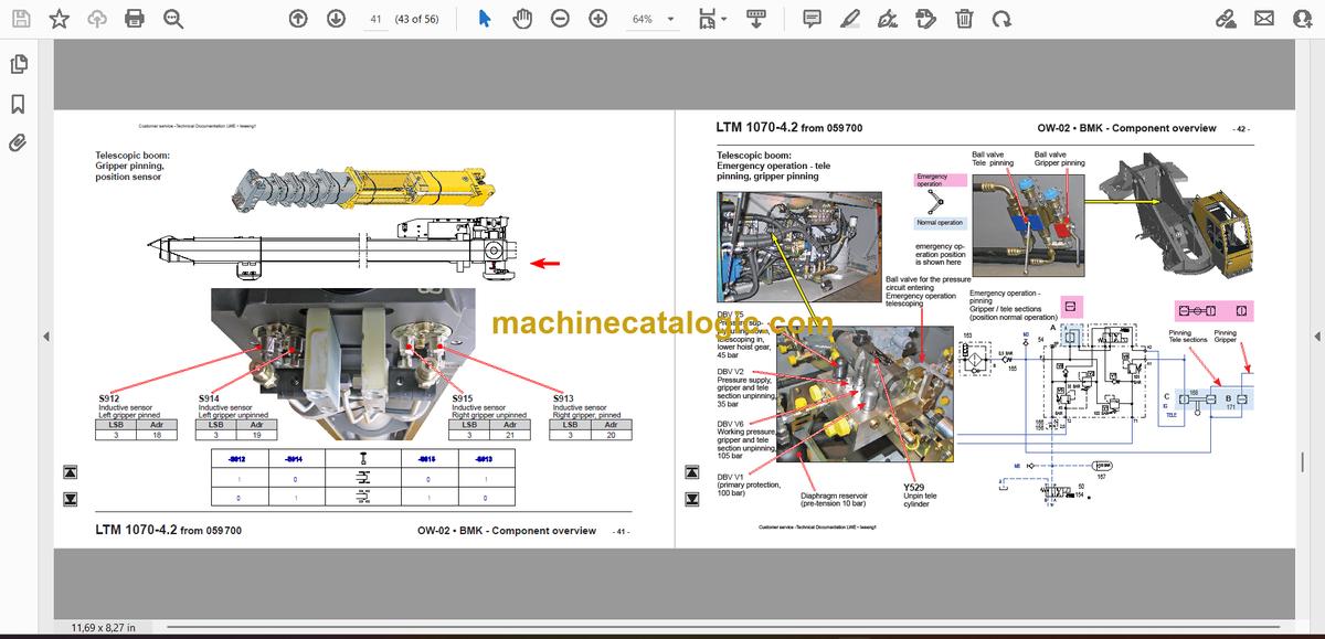
- Teleteilverbolzung, Positionsgeber
- Zangenverbolzung, Positionsgeber
- Notbetrieb Televerbolzung Zangenverbolzung
- Zusatzausrüstung Hydraulisch verstellbare Klappspitze (TNZK)*:
- Ansteuerung Ausschwenken und Wippen
- Hydraulikkomponenten
- Hydraulikkomponenten, Winkelgeber
- Hubendschalter an Einfach- und Doppelklappspitze
- Zusatzheizung Thermo 90ST
- Klimaanlage
- Klimaanlage
Liebherr Crane


