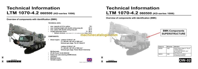
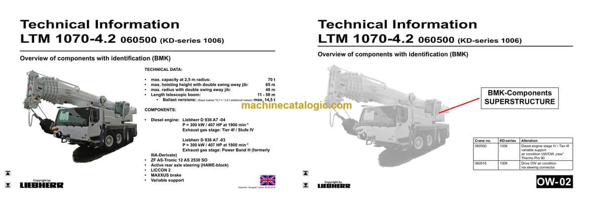
Out on site the Liebherr LTM 1070-4.2 Mobile Crane is earning its keep, and back in the workshop you’re chasing faults, tracking leaks, or hunting an electrical gremlin. That’s when the techs reach for the BMK: to tie what they see on the machine to what they see on the drawings. Component identification is what keeps you from wasting an hour stripping the wrong cover or chasing the wrong harness. This Technical Information & BMK Components Manual for SN 060508 is built exactly for that job, not for step‑by‑step repairs.
What this manual helps you do
- Identify which physical component matches a schematic tag like K15, E1, V12, or X45 on the LTM 1070-4.2.
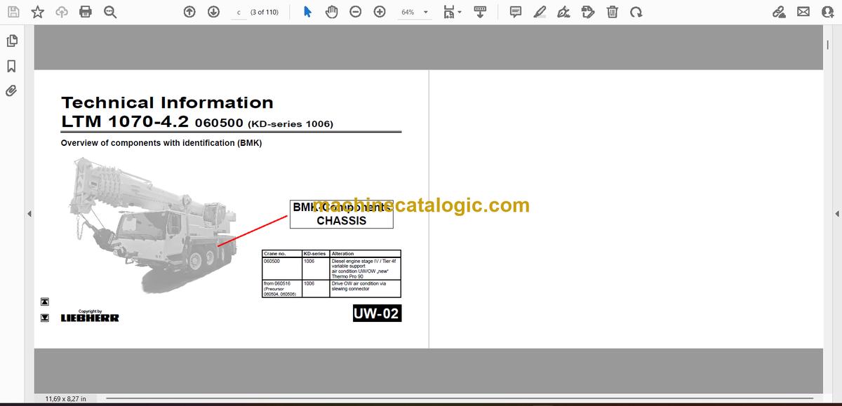
- Locate hydraulic, electrical, and control components on the carrier and superstructure using outline and layout diagrams.
- Trace harness routes and box locations so you know which panel or cover to open before you start testing.
- Cross-reference Liebherr’s internal component IDs to the right place in wiring diagrams, hydraulic schematics, or other tech docs.
- Pinpoint what a “mystery box” or valve block is actually called in Liebherr’s language so you can talk to parts or engineering.
Who this is for
This is for workshop technicians, field service techs, electrical diagnostic engineers, fleet mechanics, and training instructors who already use schematics. If you need repair procedures, torque specs, fault trees, or part numbers, you’re after a service manual or parts catalogue instead, not this BMK component identification book.
FAQ
Q: Are the diagrams clear and searchable in the PDF?
A: Yes, these are normally delivered as a readable PDF where you can zoom in on component layouts and search for BMK IDs.
Q: Does it cover both the carrier and the superstructure?
A: Yes, this BMK manual combines carrier and superstructure component layouts for the same LTM 1070-4.2 machine.
Q: Does it work together with other Liebherr manuals?
A: Yes, you use this alongside wiring diagrams, hydraulic schematics, parts catalogues, and service manuals to jump from a symbol or code to the real component.
Bottom line: if your main problem is “Where is this thing on the crane and what does Liebherr call it?”, this is exactly what you need. If you’re after how to fix it or which part number to order, this is the wrong book.
📘 Show Index
Table of Contents:
Carrier — Table of Contents
- Fahrzeug:
- Ansicht von vorne, Beleuchtung und Spiegel
- Ansicht von hinten, Beleuchtung
- Seitenmarkierungsleuchten rechts
- Seitenmarkierungsleuchten links, NOT-HALT
- Steckdosen, Warnsignalgeber
- Wegfahrsperre*
- Fahrerhaus:
- Bedienelemente
- Bedienelemente Mittelkonsole
- Türen und Fenster, Innenbeleuchtung
- Lüftung und Wärmetauscher
- Scheibenwisch- und waschanlage
- Bluetooth Basiseinheit – BTB, Bluetooth Terminal – BTT
- Mittelkonsole – E/A- Module, ECUs
- Mittelkonsole – Batterien, Sicherungen, Spannungswandler
- Mittelkonsole – Sicherungen, Massestützpunkt
- Mittelkonsole – Relais
- Mittelkonsole – Intervallrelais, Widerstände, Lüfter
- Notbetrieb- und Diagnosestecker
- Druckluftanlage:
- Luftpresser und Luftaufbereitungseinheit (APU)
- Druckluftvorratsbehälter
- Druckgeber und Druckschalter
- Magnetventile Nebenverbraucher
- Druckluftventile Fahrerhaus
- Bremsrelais-, Überlastschutz-, Überströmventil
- Druckluftkreise – Messstellen
- Anhängersteuerventil
- Scheibenbremsanlage:
- Übersicht Bremsbelag Überwachung
- Bremsbelag Überwachungsanzeige
- ABV-Regelventile
- Dieselmotor D936 A7 -04:
- Abgasstufe Tier 4f / Stufe IV:
- Übersicht Antriebsaggregat
- Motorsteuergerät
- Übersicht Einspritzseite
- Kraftstoffpumpen
- Kraftstoff – Niederdrucksensoren
- Liebherr Daisy-Chain Diesel-Einspritzsystem
- Injektoren LCR-I S2
- Typenschild
- Übersicht Abgasseite
- Ladeluft-Sensoren und -Vorwärmung
- Abgasklappe
- Abgasturbolader mit Wastegate
- Übersicht Schwungradseite, Generator
- Drehzahlsensoren
- Übersicht Lüfterseite
- Kühlmittelsystem
- Ölkreislauf
- Abschlusswiderstand CAN2 (LIDEC2 / ECU2)
- Abschlusswiderstand CAN2 (LIDEC2 / ECU2)
- Dieselmotor D936 A7 -03:
- Power Band H (früher IIIA-Derivat):
- Übersicht Antriebsaggregat
- Externe Abgasrückführung eAGR
- Abgasklappe
- Luftfilter Unterdruck
- Intercooler Temperatur Sensor
- Abgasnachbehandlung SCR:
- Übersicht Abgasnachbehandlung SCR Stufe IV
- Übersicht Harnstoffanlage SCR Stufe IV
- AdBlue Tank und Tankgebereinheit
- AdBlue Leitungen
- SCR Pumpenmodul
- Abgasanlage
- Umgebungsluft-Sensor, Abgasklappe
- Diesel-Kraftstoffanlage:
- Kühlanlage:
- Geberübersicht:
- Kühlmittelgeber, Temperaturgeber (OBD)
- Automatisiertes Schaltgetriebe:
- ZF 12 AS 2530 SO (ohne Intarder)
- Hydraulik:
- Hydraulikpumpen – Übersicht
- Hydraulikpumpen – Übersicht
- Temperatursensor Hydrauliköl, Hydraulikölbehälter
- Antriebsstrang:
- Übersicht, Schaltbedingungen
- Verteilergetriebe Kessler VG 2700 (zweistufig)
- Querdifferentialsperren, Zuschaltung Achse 1
- Querdifferentialsperren, Achsen 3 und 4
- ABV – Raddrehzahlsensoren
- Lenkung:
- Lenkung vom Oberwagen aus
- Lenkgetriebe ZF-SERVOCOM, Mangelüberwachung
- Ölversorgung Lenkkreis 1, Mangelüberwachung
- Ölversorgung Lenkkreis 2, Mangelüberwachung
- Aktive Hinterachslenkung:
- CAN-Ventile (HAWE)
- Ventilblock Achse 3 bis 4
- Vorspannventil, Messanschlüsse MP6
- Winkelgeber
- Lenk- und Zentrierzylinder, Sicherheitsventile
- Abstützung:
- Neigungsaufnehmer
- Abstützventile – rechts
- Abstützventile – links
- Ausschiebezylinder Schiebeholm
- Abstützzylinder
- Druckaufnehmer für Stützkraftanzeige*
- Variable Abstützung*:
- Abstützkraftgeber, Laserlängengeber (ab 060500)
- Schiebeholmüberwachung mit Seillängengeber (ab 060544)
- Stützdrucküberwachung mit Druckaufnehmer (ab 060657)
- Achsfederung:
- Niveaugeber – Achsfederung
- Ventilblock – Achsfederung rechts
- Ventilblock – Achsfederung links
- Ventile für Achsdruck-Ausgleich; blockiert / gefedert
- Sonderausstattung:
- Wirbelstrombremse Telma Focal 2200
- Zusatzheizung Thermo Pro 90
- Klimaanlage (bis 060515)
- Klimaanlage (ab 060516)
- Fremdeinspeisung 110 V / 230 V*
- Index
Superstructure — Table of Contents
- Oberwagen allgemein:
- Beleuchtung Drehbühne
- Beleuchtung Ausleger
- LMB-Warneinrichtung (EN 13000)
- Kraftstofftank und Tankgeber
- Zentralschmieranlage
- Ausleger-Richtung
- Wegfahrsperre*
- Krankabine:
- Steuerstand – Liccon-Monitor, Pedale, Ethernet
- Steuerstand – Meisterschalter, LSB-TE1 rechts
- Steuerstand – Meisterschalter, LSB-TE2 links
- Steuerstand – Bedien- und Kontrolleinheit
- Kabineninstallation – Innenausstattung
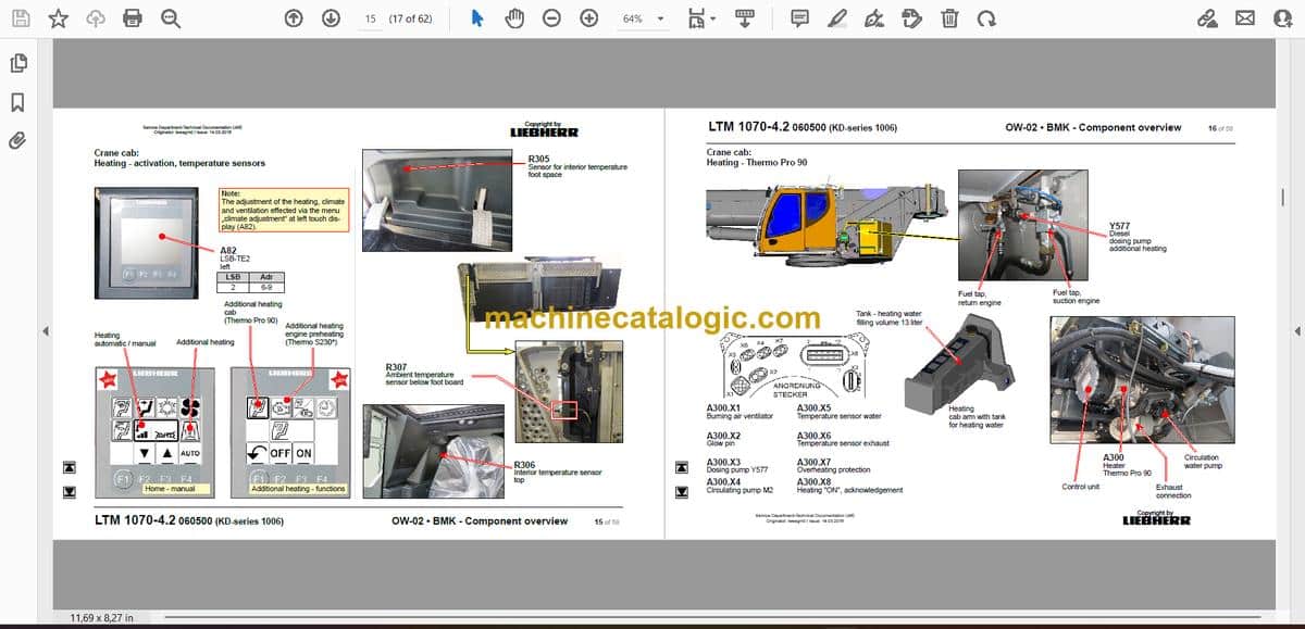
- Heizung – Ansteuerung, Temperatursensoren
- Heizung – Thermo Pro 90
- Heizung – Heizklimagerät
- Wischermotoren, Waschpumpe, Podest
- Schaltschrank Krankabine:
- Schwenkrahmen – Sicherungen
- Relais (ab 060500), Widerstandsmodul
- Relais (ab 060516)
- Montageblech – LSB-Master, Spannungswandler
- Universelles Ein-/Ausgabe-Modul, Datenlogger II
- Diagnosestecker, Ferndiagnose
- Steckerblech Drehbühne / Kabine
- NOTBETRIEB – XNOT-Stecker
- NOTBETRIEB Widerstände, Luftzirkulation
- Kranhydraulik:
- Übersicht Hydraulikkomponenten
- Übersicht Messanschlussplatte
- Hauptsteuerblock
- Hauptsteuerblock
- Druckgeber, Temperaturgeber Hydrauliköl
- Ölfilter
- Druckstufen – Teleskopieren
- Televerbolzung, Zangenverbolzung – Notbetrieb
- Hubwerk 1
- Hubwerk 2*
- Wippen
- Drehwerk – Ansteuerung
- Drehwerk – Bremse, Inkrementalgeber
- Nebenverbraucherventile
- Drehbühnenarretierung
- Kabine kippen
- Ballastierung
- Teleskopausleger:
- Anlenkstück, „Ausleger steil“
- Auslegerkopf
- Teleteilverbolzung, Positionsgeber
- Zangenverbolzung, Positionsgeber
- Sonderausstattung:
- Doppelklappspitze hydraulisch* – Elektrik
- Doppelklappspitze hydraulisch* – Hydraulik
- Doppelklappspitze hydr.* – Hydraulikkomponenten
- Klimaanlage* (ab 060500)
- Klimaanlage (ab 060516)
- Notbetätigung Kranhydraulik*
- Ölkühler 2*
- Kameraüberwachung
- Index
Liebherr Crane


