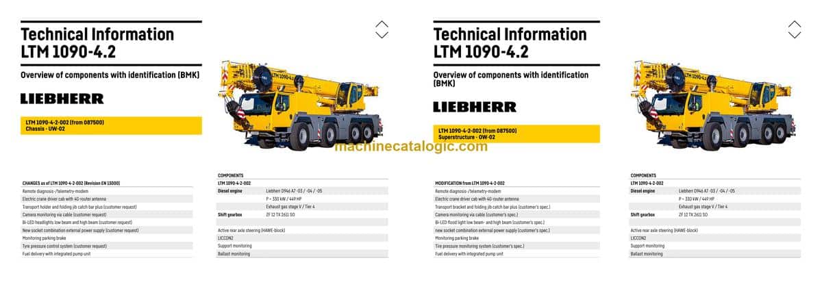
The Liebherr LTM 1090-4.2 Mobile Crane earns its keep on sites where setup time is tight and lifts can’t wait, so knowing exactly where every box, valve, and sensor sits matters. The Technical Information & BMK Components Manual for SN 087916 is what techs grab when a fault code points to “K15” or “X45” and they need to find it on the iron, not on paper. Workshop guys, field service, and anyone chasing wiring or hydraulic issues use this to stop guessing and start walking straight to the right spot. That’s how you save time and, honestly, save the customer money.
What this manual helps you do
- Identify which physical component matches a schematic tag like E1, V12, K3, or X45 on the LTM 1090-4.2.
- Locate components on the carrier or superstructure using outline views and machine overlays.
- Trace reference designators from wiring or hydraulic diagrams to their real-world mounting position.
- Cross-reference a fault code or drawing symbol to Liebherr’s own component naming and IDs.
- Find where major assemblies and boxes are installed so you can plan access before you start stripping panels.
Who this is for
This is aimed at workshop technicians, field service techs, electrical diagnostic engineers, fleet mechanics, and training instructors who need clear component identification. If you’re after repair steps, torque specs, or part numbers, you actually want the service manual or parts catalogue instead.
FAQ
Q: Is the PDF clear and searchable?
A: Yes, this kind of BMK manual is typically provided as a readable PDF you can zoom and search by component ID or keyword.
Q: Does it cover both the carrier and the superstructure?
A: Yes, it combines BMK information for the carrier and the superstructure of the LTM 1090-4.2 into one product.
Q: Does it work with other Liebherr documents?
A: Yes, the BMK component identification ties directly into Liebherr wiring diagrams, hydraulic schematics, service manuals, and parts catalogues.
Bottom line: If you need to find and identify components on a Liebherr LTM 1090-4.2 by their BMK or schematic tag, this is the right manual; if you want repair instructions or part numbers, it’s not.
📘 Show Index
Table of Contents:
Carrier — Table of Contents
- Table of contents
- Chassis:
- Lighting front and mirrors
- View from rear- lighting
- Side view right- side marker lights
- Side view left- side marker lights
- Sockets, warning signal sensor
- Trailer coupling – voltage converter
- Immobiliser*, emergency stop*
- Driver cab:
- Control elements
- Control elements centre console
- BTB, remote control module – BTT
- Doors and windows, interior lighting
- Screen wiper and – washer
- Ventilation and heat exchanger
- Additional heating Thermo Pro 90
- Air-conditioner
- Telemetry – FMS-interface, modem
- Wiring loom – backup camera, radio
- Driver cab – centre console:
- Battery box and fuses
- I/O modules, BTB
- Fuses
- Centre console – relay
- Control unit, electrical components
- Voltage converter, fan
- Diagnosis plug
- Pneumatic system:
- Air compressor and air dryer
- Compressed air reservoir
- Pneumatic valves in the driver cab
- Brake relay- / overload protection valve
- Filter and overflow valve / adapter valve
- Pressure sensors and pressure switches
- Monitoring parking brake (from 087500)
- Solenoid valve for auxiliary consumer
- Pneumatic system – brake system:
- Disk brake system
- Brake pad monitoring
- Brake pad monitoring display
- ABV – control valve
- ABV – wheel speed sensors
- Hill start assist (Hill Start Aid)
- Compressed air circuits – measuring points
- Overview drive assembly:
- Installation view
- Installation diesel engine
- Diesel engine D946 A7 -03 (eAGR) 04 (SCR) / -05 (SCRF):
- Engine control unit
- Overview injection side
- Fuel pumps
- Fuel low pressure sensors
- Liebherr Daisy-Chain diesel injection system
- Injectors LCR-I S2
- Type plates:
- Overview exhaust gas side
- Charge air sensors and -preheating
- Exhaust gas flap
- Exhaust gas turbo charger with wastegate
- Overview flywheel side and generator
- Speed sensors
- Overview fan side
- Cooling agent
- Oil circuit
- Temperature sensor OBD
- Terminal resistor engine-CAN (ECU-CAN2)
- Diesel engine D946 A7 -04 (Stage IV SCR) / -03 (Powerband H)
- Terminal resistor CAN-LIDEC (ECU-CAN2)
- Diesel engine D946 A7 -03 (eAGR) / Power Band H:
- External exhaust gas return eAGR
- Intercooler temperature sensor
- Exhaust after treatment SCRonly / SCRF:
- AdBlue tank with AdBlue tank gauge unit (extraction module)
- SCR-pump module and compressed air supply
- AdBlue lines and cooling water-heating valves
- Exhaust gas system exhaust after treatment “SCRonly”:
- Exhaust gas system exhaust after treatment “SCRF”:
- Air filter system:
- Air filter-vacuum, ambient air sensor, air flap*
- Diesel fuel system:
- Cooling system:
- Cooler – fan drive, level sensor
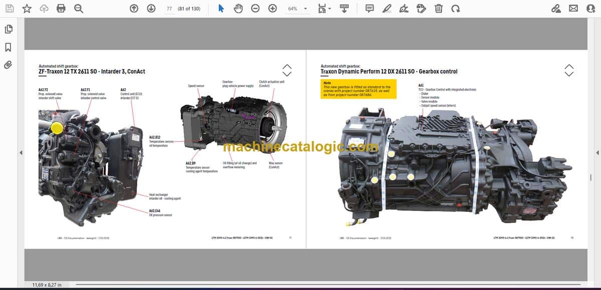
- Automated shift gearbox:
- ZF-Traxon 12 TX 2611 SO (intarder 3)
- ZF-Traxon 12 TX 2611 SO – Intarder 3, ConAct
- Traxon Dynamic Perform 12 DX 2611 SO – Gearbox control
- Traxon Dynamic Perform 12 DX 2611 SO – Intarder
- Traxon Dynamic Perform 12 DX 2611 SO – Wet starting clutch
- Hydraulic:
- Hydraulic oil reservoir
- Temperature sensor hydraulic oil, check valve
- Hydraulic pumps – overview
- Hydraulic pumps – crane hydraulic
- Drive train:
- Overview
- Distribution gearbox Kessler VG 2700 (two stage)
- Road/off-road switchover
- Transversal differential lock axle 2 and 4
- Long. and transv. differential lock axle 3
- Steering:
- Steering from superstructure
- Steering gear ZF-SERVOCOM
- Oil supply steering circuit 1, deficiency monitoring
- Oil supply steering circuit 2, deficiency monitoring
- Active rear axle steering:
- CAN-Valves (HAWE)
- Valve block
- Measuring connections MP6, MP8, MP9
- Angle sensor
- Steering- and centering cylinder, safety valves
- Support:
- Inclination sensor
- Support valves – right
- Support valves – left
- Sliding beam – extension cylinder
- Sliding beam – monitoring with rope length sensor
- Support cylinder
- Support cylinder – monitoring
- Variant – support monitoring
- Variant – VarioBase
- Axle suspension:
- Oil supply, control valve blocked/sprung
- Level sensor- axle suspension
- Valve block – axle suspension right
- Valve block – axle suspension left
- Special equipment:
- Dolly operation – diaphragm reservoir overview
- Dolly operation – switch over diaphragm reservoir, additional hydraulics
- Engine preheating – Thermo Top Pro 150 and Air Top Evo 55
- Additional heating UW Air Top – Air Top 2000 STC
- Emergency control – crane hydraulic
- Emergency control – support
- External power supply 110 V / 230 V
- Battery charger
- Back-up camera
- Tire pressure monitoring system*
- Central lubrication system*
- Attachment:
- Index
- Limitation of liability / Disclaimer
Superstructure — Table of Contents
- Inhaltsverzeichnis
- Oberwagen allgemein:
- Beleuchtung Drehbühne
- Beleuchtung Ausleger
- LMB-Warneinrichtung (EN 13000)
- Zentralschmieranlage
- Drehwerk – Auslegerrichtung
- Wegfahrsperre*
- Krankabine:
- Steuerstand – LICCON-Monitor, Pedale, Ethernet
- Steuerstand – Meisterschalter, LSB-TE1 rechts
- Steuerstand – Meisterschalter, LSB-TE2 links
- Steuerstand – Bedien- und Kontrolleinheit
- Steuerstand – Bedienelemente Seitenkonsole
- Kabineninstallation – Innenausstattung
- Kabineninstallation – Wischermotoren, Waschpumpe
- Podest Kabine
- Krankabine – Heizung:
- Ansteuerung, Temperatursensoren
- Heizklimagerät
- Thermo Pro 90
- Krankabine – Schaltschrank:
- Schwenkrahmen – Sicherungen
- Relais, Widerstandsmodul
- LSB-Master, Spannungswandler, Luftzirkulation
- UEA-Modul, Datenlogger 2
- Telemetrie und Ferndiagnose, Notbetrieb Widerstände
- Diagnosestecker
- Steckerblech Drehbühne / Kabine
- Kranhydraulik:
- Hydraulikpumpen (Unterwagen)
- Übersicht Hydraulikkomponenten
- Übersicht Messanschlussplatte, Ölkühler
- Hauptsteuerblock mit Hubwerk 2
- Hauptsteuerblock – Druckstufe, Stellungsüberwachung, Druckgeber
- Drehwerk – Ansteuerung, Bremse
- Wippwerk
- Hubwerk 1 – Ventile und Anschlüsse
- Hubwerk 2* – Winde
- Hubwerk 2* – Ventile und Anschlüsse
- Hilfsverbraucher, Drehbühnenarretierung
- Ballast – Schwenkarm (Ballastierung rechts)
- Ballast – Schwenkarm (Ballastierung links)
- Ballastüberwachung
- Tele- / Zangenverbolzung, Hydraulikölfilter
- Dollybetrieb* (Anhänger für Auslegertransport USA)
- Notbetätigung Kranhydraulik*
- Teleskopausleger:
- Anlenkstück
- Auslegerkopf
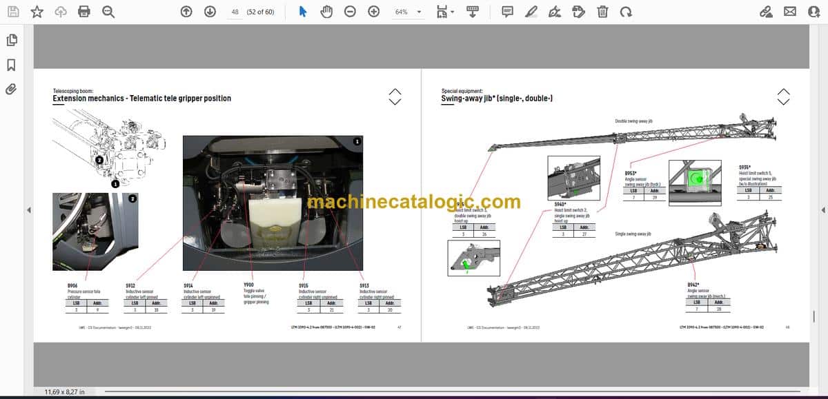
- Ausschubmechanik – Telematik Televerbolzung
- Ausschubmechanik – Telematik Zangenposition
- Sonderausstattung:
- Klappspitze* (Einfach-, Doppel-)
- Klappspitze* – hydraulisch
- Klappspitze* – Schwenkzylinder
- Klimaanlage
- Kameraüberwachung* – Ausleger, Drehbühne
- Anhang:
- Index
- Haftungsbegrenzung / Disclaimer
Liebherr Crane


