Format: PDF (Printable Document)
File Language: English
File Pages: 182
File Size: 38.32 MB (Speed Download Link)
Brand: Liebherr
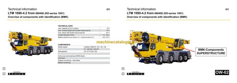
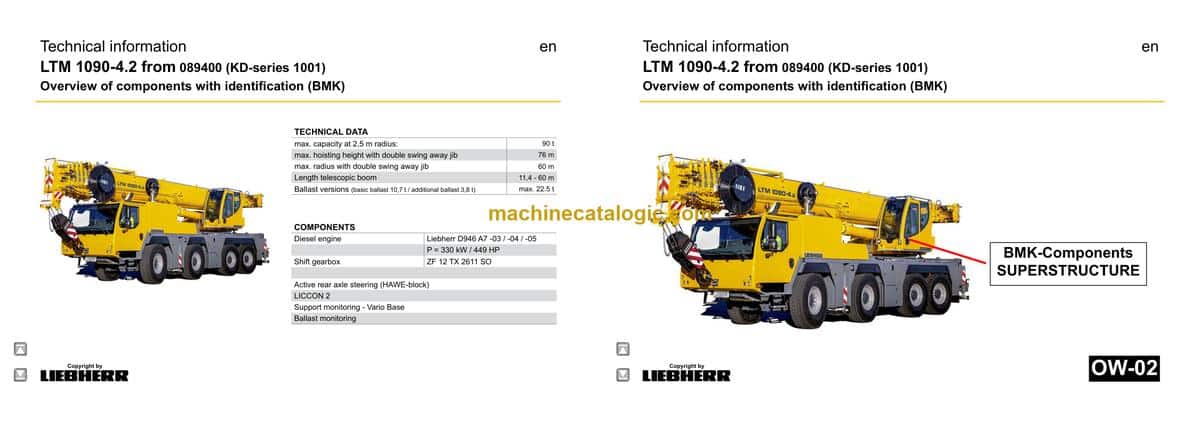
Model: LTM 1090-4.2 Mobile Crane
Components: Carrier + Superstructure
Serial No: SN 089657
Date: 2023
Type of Document: Technical Information & BMK Components Manual
$ 80
The Liebherr LTM 1090-4.2 Mobile Crane earns its keep on sites where you’re lifting serious loads all day, so knowing exactly where every sensor, valve, and relay sits is what keeps downtime (and bills) down. A BMK / component identification manual is what the techs grab when the wiring diagram says “K15” and they need to know where that actually lives on the crane. In a workshop, that’s the difference between a 20‑minute job and burning half a day just finding the right box. This Technical Information & BMK Components Manual is built for that kind of work, not for step‑by‑step repairs.
What this manual helps you do
Who this is for
This suits a workshop technician, field service tech, electrical diagnostic engineer, fleet mechanic, or training instructor who already has or plans to use service, wiring, or parts manuals. If you mainly need repair procedures, torque specs, or part numbers, you want a service manual or parts catalogue instead, not this BMK.
FAQ
Q: Are the diagrams clear and searchable?
A: Yes, this kind of BMK manual is normally supplied as a readable PDF with clear component outlines and searchable text labels.
Q: Does it cover both carrier and superstructure?
A: Yes, it combines the BMK component identification for the lower carrier and the upper crane superstructure in one product.
Q: Does it work with other Liebherr documentation?
A: Yes, it’s meant to be used alongside Liebherr wiring diagrams, hydraulic schematics, service manuals, and parts catalogues by matching the same reference designators.
Bottom line: If you need to know “where is this component on my LTM 1090-4.2, SN 089657?” this is exactly what you want; if you’re after how to repair or which part to order, it’s not.
Chassis:………………………………………………………………………………….. 5
Lighting front and mirrors……………………………………………………………. 5
Lighting rear……………………………………………………………………………… 6
Side marker lights right………………………………………………………………. 7
Side marker lights left………………………………………………………………… 8
Sockets, warning signal sensor…………………………………………………… 9
Trailer coupling – voltage converter…………………………………………….. 10
Emergency stop*…………………………………………………………………….. 10
Immobiliser*……………………………………………………………………………..11
► Driver cab:…………………………………………………………………………….. 12
Control elements……………………………………………………………………… 12
Screen wiper and washer, heating valves…………………………………… 13
Ventilation and heating driver cab………………………………………………. 14
Air-conditioner…………………………………………………………………………. 15
Interior lighting, doors………………………………………………………………. 16
Basic unit – BTB
remote control module – BTT…………………………………………………….. 17
Control elements centre console……………………………………………….. 18
Telemetry FMS-interface…………………………………………………………… 19
Wiring loom – backup camera, radio…………………………………………… 19
Centre console – batteries, battery main switch,
Fuses battery box……………………………………………………………………. 20
Center console – I/O modules, BTB……………………………………………. 21
Centre console – fuses……………………………………………………………… 22
Centre console – relay………………………………………………………………. 23
Centre console – control units, interval relay………………………………… 24
Centre console – voltage converter, fan………………………………………. 25
Centre console – diagnosis plug………………………………………………… 26
► Pneumatic system:………………………………………………………………… 27
Air compressor and air dryer…………………………………………………….. 27
Pressure reservoir…………………………………………………………………… 28
Pneumatic valves in the driver cab…………………………………………….. 29
Brake relay- / overload protection valve……………………………………… 30
Filter and overflow valve / adapter valve…………………………………….. 31
Pressure sensors and pressure switches……………………………………. 32
Solenoid valve for auxiliary users………………………………………………. 33
Disk brake system…………………………………………………………………… 34
Disk brake system – brake pad control ………………………………………. 35
Brake pad monitoring indicator………………………………………………….. 36
ABV – regulating valves……………………………………………………………. 37
ABV – wheel speed sensors………………………………………………………. 38
Hill start assist (Hill Start Aid)…………………………………………………….. 39
Compressed air circuits – measuring points…………………………………. 40
Compressed air circuits – measuring points…………………………………. 40
► Overview drive assembly:………………………………………………………. 41
Installation view………………………………………………………………………. 41
Installation diesel engine …………………………………………………………. 42
Copyright by
liebherr
LWE – Customer Service – Documentation
Author: lweegm0 / Issue: 08.05.2020
LTM 1090-4.2 from 089400 (KD-series 1001) UW-02 • BMK – Component overview 2 of 118
► Diesel engine D946 A7 -03 (eAGR) 04 (SCR) / -05 (SCRF):……….. 43
Engine control unit…………………………………………………………………… 43
Overview injection side…………………………………………………………….. 44
Fuel pumps…………………………………………………………………………….. 45
Fuel low pressure sensors………………………………………………………… 46
Liebherr Daisy-Chain diesel injection system………………………………. 47
Injectors LCR-I S2…………………………………………………………………… 48
Type plates:……………………………………………………………………………. 48
Overview exhaust side……………………………………………………………… 49
Charge air sensors and -preheating…………………………………………… 50
Exhaust gas flap……………………………………………………………………… 51
Exhaust gas turbo charger with wastegate………………………………….. 52
Overview flywheel side and generator………………………………………… 53
Speed sensors………………………………………………………………………… 54
Overview fan side……………………………………………………………………. 55
Cooling agent………………………………………………………………………….. 56
Oil circuit………………………………………………………………………………… 57
Terminal resistor CAN-LIDEC (ECU-CAN2)………………………………… 58
Terminal resistor engine-CAN (ECU-CAN2)………………………………… 59
Diesel engine D946 A7 -03 (eAGR) / Power Band H:………………… 60
External exhaust gas return eAGR…………………………………………….. 60
Intercooler temperature sensor………………………………………………….. 61
Exhaust gas system………………………………………………………………. 62
Exhaust after treatment “SCRonly” – overview…………………………….. 62
Exhaust after treatment “SCRonly” – sensors………………………………. 63
Exhaust after treatment “SCRF” – overview…………………………………. 64
Exhaust after treatment “SCRF” – sensors………………………………….. 65
AdBlue tank with AdBlue tank gauge unit (extraction module)……….. 66
SCR-pump module and compressed air supply…………………………… 67
AdBlue lines and cooling water-heating valves……………………………. 68
► Air filter system:……………………………………………………………………. 69
Air filter vacuum, ventilation flap*……………………………………………….. 69
► Diesel fuel system:………………………………………………………………… 70
Fuel prefilter and tank………………………………………………………………. 70
► Cooling system:…………………………………………………………………….. 71
Cooler – fan drive, level sensor………………………………………………….. 71
► Sensor overview:…………………………………………………………………… 72
Temperature sensor (OBD)……………………………………………………….. 72
► Automated shift gearbox:………………………………………………………. 73
ZF-Traxon 12 TX 2611 SO (Intarder3)………………………………………… 73
Intarder 3, clutch actuation unit (ConAct)……………………………………. 74
► Hydraulic:……………………………………………………………………………… 75
Hydraulic oil tank…………………………………………………………………….. 75
Temperature sensor hydraulic oil, check valve…………………………….. 76
Hydraulic pumps – overview………………………………………………………. 77
Hydraulic pumps – crane hydraulic…………………………………………….. 78
► Drive train:…………………………………………………………………………….. 79
Overview………………………………………………………………………………… 79
Distribution gearbox Kessler VG 2700 (two stage)……………………….. 80
Road/off-road switchover………………………………………………………….. 81
Transversal differential lock axle 2 and 4…………………………………….. 82
Long. and transv. differential lock axle 3……………………………………… 83
► Steering:……………………………………………………………………………….. 84
Steering from superstructure…………………………………………………….. 84
Steering gear ZF-SERVOCOM…………………………………………………. 85
Oil supply steering circuit 1, deficiency monitoring……………………….. 86
Oil supply steering circuit 2, deficiency monitoring……………………….. 87
► Active rear axle steering………………………………………………………… 88
CAN-Valves (HAWE)……………………………………………………………….. 88
Valve block……………………………………………………………………………… 89
Measuring connections MP6, MP8, MP9…………………………………….. 90
Angle sensor…………………………………………………………………………… 91
Steering- and centering cylinder, safety valves……………………………. 92
► Support…………………………………………………………………………………. 93
Level sensor…………………………………………………………………………… 93
Support valves – right……………………………………………………………….. 94
Support valves – left…………………………………………………………………. 95
Sliding beam – extension cylinder ……………………………………………… 96
Sliding beam – monitoring with rope length sensor……………………….. 97
Support cylinder………………………………………………………………………. 98
Support cylinder – monitoring…………………………………………………….. 99
Variant – support monitoring…………………………………………………….. 100
Variant – Vario Base……………………………………………………………….. 101
► Axle suspension:…………………………………………………………………. 102
Oil supply, control valve blocked/sprung…………………………………… 102
Level sensor- axle suspension………………………………………………… 103
Valve block – axle suspension right…………………………………………… 104
Valve block – axle suspension left…………………………………………….. 105
► Special equipment:………………………………………………………………. 106
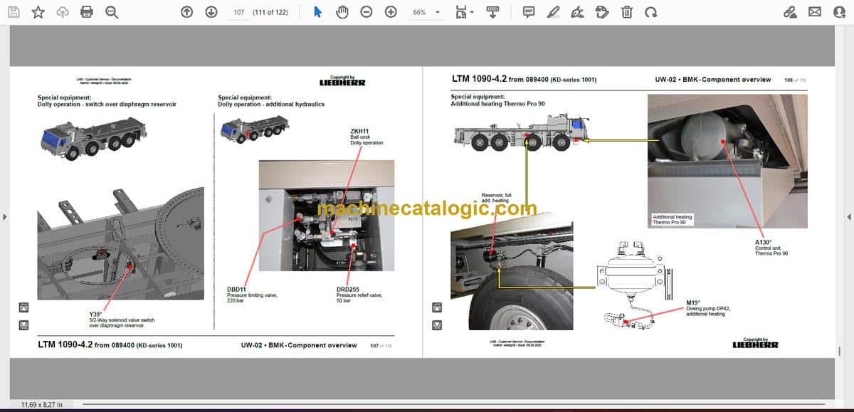
Dolly operation – diaphragm reservoir overview…………………………. 106
Dolly operation – switch over diaphragm reservoir………………………. 107
Dolly operation – additional hydraulics………………………………………. 107
Additional heating Thermo Pro 90……………………………………………. 108
Engine preheating – Thermo Top Pro 150 and Airtop Evo 55……….. 109
Additional heating UW Airtop – Air Top 2000STC………………………….110
Hydraulic emergency control…………………………………………………….111
Emergency control crane hydraulic (UW)……………………………………111
External power supply 110 V / 230 V………………………………………….112
Battery charger……………………………………………………………………….113
Back-up camera………………………………………………………………………114
► Index…………………………………………………………………………………….115
Superstructure general:………………………………………………………..3
Lighting slewing platform…………………………………………………………3
Lighting boom………………………………………………………………………..4
LMB – warning device (EN 13000)…………………………………………….5
Central greasing device…………………………………………………………..6
Slewing gear – boom direction …………………………………………………7
Immobiliser*…………………………………………………………………………..8
► Crane cabin:…………………………………………………………………………9
Control stand – Liccon – monitor, pedals, ethernet……………………….9
Control stand – joystick, LSB-TE1 right…………………………………….10
Control stand – joystick, LSB-TE2 left……………………………………… 11
Control stand – operation- and control unit……………………………….12
Control stand – control elements side console…………………………..13
Platform cab…………………………………………………………………………13
cab installation – interior furnishing………………………………………….14
cab installation – wiper motor, washer pump……………………………..15
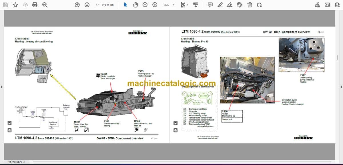
Heating – activation, temperature sensors………………………………..16
Heating – heating air conditioning……………………………………………17
Heating – Thermo Pro 90……………………………………………………….18
Switch cabinet crane cabin:………………………………………………..19
Cab cabinet – air circulation……………………………………………………19
Tilting frame – fuses………………………………………………………………20
Relay, resistor modules………………………………………………………….21
Mounting plate – LSB-master, voltage converter………………………..22
UEA module, data logger 2…………………………………………………….23
Remote diagnosis…………………………………………………………………24
EMERGENCY OPERATION resistors…………………………………….24
Diagnosis plug……………………………………………………………………..25
Plug plate slewing platform / cab…………………………………………….26
► Crane hydraulic:…………………………………………………………………27
Hydraulic pumps (chassis)……………………………………………………..27
Overview hydraulic components……………………………………………..28
Overview metering connector plate…………………………………………29
Main control block with hoist gear 2…………………………………………30
Main control block – pressure stage, position monitoring…………….31
Main control block – pressure sensor……………………………………….31
Slewing gear – activation, brake………………………………………………32
Luffing gear………………………………………………………………………….33
Hoist gear 1 – valves and connections……………………………………..34
Hoist gear 2* – winch……………………………………………………………..35
Hoist gear 2* – valves and connections……………………………………36
Auxiliary consumer, locking slewing platform……………………………37
Ballast – swivel arm (ballasting right)……………………………………….38
Ballast – swivel arm (ballasting left)…………………………………………39
Ballast monitoring…………………………………………………………………40
Tele- / gripper pinning, hydraulic oil filter………………………………….41
Oil cooler……………………………………………………………………………..42
Copyright by
liebherr
LWE – Customer Service – Documentation
Author: lweegm0 / Issue: 24.01.2020
LTM 1090-4.2 from 089400 (KD-series 1001) OW-02 • BMK – Component overview 2 of56
* = Customer‘s spec.
Note:
All stated pressures meet the values of December 2018!
Dolly operation* (dolly for boom transport USA)………………………..43
Emergency control crane hydraulic*………………………………………..44
► Telescoping boom:……………………………………………………………..45
Base section………………………………………………………………………..45
Boom head………………………………………………………………………….46
Extension mechanics – Telematic tele pinning…………………………..47
Extension mechanics – Telematic tele gripper position……………….48
► Special equipment:……………………………………………………………..49
Swing-away jib* (single-, double-)…………………………………………..49
Swing away jib* – hydraulically………………………………………………..50
Swing away jib* – slewing cylinder…………………………………………..51
Air-conditioner………………………………………………………………………52
Camera monitoring boom*……………………………………………………..53
Camera monitoring slewing platform*………………………………………53
► Index………………………………………………………………………………….54


