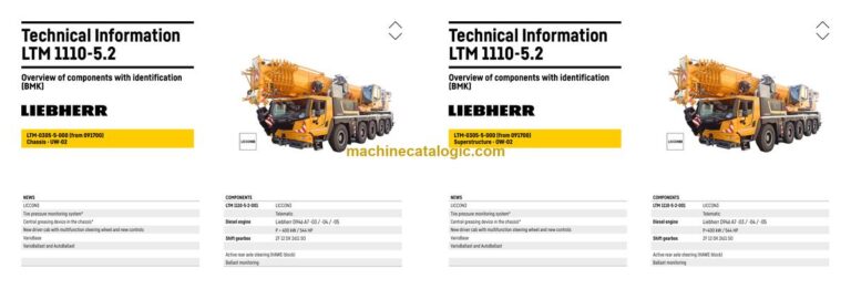
The Liebherr LTM 1110-5.2 Mobile Crane earns its keep on sites where setup space is tight and you still need serious reach and capacity. When something acts up, the first people reaching for a BMK / component identification manual are usually the electrical and hydraulic guys trying to match a fault or symbol to a real part on the machine. In a workshop, knowing exactly where Liebherr put “K15” or “V12” saves a lot of wasted time and wrong guesses. This Technical Information and BMK Components Manual for SN 091838 is built for that kind of work, not for how-to repairs.
What this manual helps you do
- Identify which physical component matches a reference like E1, K3, or X45 in your wiring or hydraulic diagrams.
- Locate the exact mounting position of sensors, valves, relays, and control units on the carrier and superstructure.
- Trace harness routes and component groups using outline and layout views of the crane.
- Cross-reference Liebherr’s internal component IDs with items mentioned in service information or fault code readouts.
- Pinpoint components on visual overlays so new techs learn the machine layout faster and stop hunting blindly.
Who this is for
This is aimed at workshop technicians, field service techs, electrical diagnostic engineers, fleet mechanics, and training instructors who already have or plan to use wiring diagrams and service info. If you mainly need repair procedures, torque specs, or part numbers, you want the service manual and parts catalogue instead, not this BMK.
FAQ
Q: Is the PDF clear and searchable enough to use on a laptop in the shop?
A: Yes, these BMK PDFs are normally scanned or generated so diagrams are readable and text can be searched by component ID.
Q: Does it cover both the carrier and the superstructure layouts?
A: Yes, this Technical Information & BMK Components Manual covers component identification for both carrier and superstructure on this crane.
Q: Does it work together with Liebherr wiring diagrams and parts catalogues?
A: Yes, the BMK is meant to sit beside those; you match the reference designator in the diagram to the BMK, then go to the parts or service info once you’ve found the part.
Bottom line: If your main question is “Where is this component on my Liebherr LTM 1110-5.2?” this is exactly the right manual. If your main question is “How do I fix or order it?” this is not the one you need.
📘 Show Index
Table of Contents:
Carrier — Table of Contents
- Table of contents
- Vehicle:
- View from front, lighting and mirror
- View from rear, lighting
- Side marker lights right
- Side marker lights left
- Sockets, warning signal sensor
- Reversing camera
- Front flap driver cab
- Electrics – ground and distributor plug W6/W7
- Electrics – ground and distributor plug W6/W9
- Electrics – ground and distributor plug W6/W8/W21
- Electrics – ground and distributor plug W34/W111
- Driver cab:
- Control elements
- Doors and windows, interior lighting
- Locking system and immobilizer*
- Roof bracket
- Multifunction steering wheel – remote control
- Ventilation and heat exchanger
- Heating and heating air conditioning
- Heating – temperature sensors
- Air-conditioner
- Screen wiper and – washer
- Radio
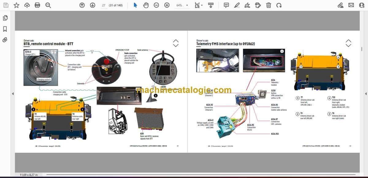
- BTB, remote control module – BTT
- Telemetry FMS interface (up to 091862)
- Telemetry FMS interface (from 091863)
- Driver‘s cab – Assistance system:
- Blind spot information system (BSIS)
- Moving Off Information System (MOIS)
- Reversing information system (REIS)
- Access for calibration
- Driver cab – centre console:
- Battery, high current board
- I/O-modules, ECUs
- Fuses
- Relays
- Plug and components
- Monitoring parking brake
- Emergency operation- and diagnosis plug
- Pneumatic system:
- Compressor (air compressor), air treatment unit (APU)
- Compressed air reservoir
- Pressure sensors and pressure switches
- Pneumatic valves driver cab
- Solenoid valve for auxiliary consumer
- ABV regulating valves
- Compressed air circuits – measuring points
- Pneumatic system – brake system:
- ABV wheel speed sensors
- Overview – brake pad monitoring
- Overview brake system
- Brake relay- / overload protection valve
- Monitoring display brake pad
- Hill start assist (Hillstart Aid)
- Diesel engine D946 A7 -03 (eAGR) / -04 (SCRonly) / -05 (SCRF):
- Overview drive assembly
- Engine control unit
- Installation diesel engine
- Overview injection side
- Fuel pumps
- Fuel low pressure sensors
- Liebherr diesel injection system Daisy-Chain
- Injectors LCR-I S2, type plate
- Overview exhaust gas side
- Charge air sensors and charge air preheating
- Exhaust gas flap
- Exhaust gas turbo charger with wastegate
- Overview flywheel side, generator
- Speed sensors
- Overview fan side
- Coolant system
- Oil circuit
- Terminal resistor CAN2 (LIDEC2 / ECU2)
- Terminal resistor CAN2 (LIDEC2 / ECU2)
- Diesel engine D946 A7 -03 (eAGR) / Power Band H:
- Overview drive assembly
- External exhaust gas return eAGR
- Exhaust gas flap
- Intercooler temperature sensor
- Exhaust after treatment:
- Diesel exhaust fluid tank
- Pump module and diesel exhaust fluid lines (up to 091881)
- Pump module and diesel exhaust fluid lines (from 091882)
- Exhaust after treatment -04 (SCR only):
- Overview
- Injector and sensors
- Exhaust after treatment -05 (SCRF):
- Overview
- Injector and sensors
- Air filter system
- Air filter vacuum, air flap*
- Cooling system:
- Diesel fuel system:
- Sensor overview:
- Coolant level, ambient temperature OBD
- Automated shift gearbox:
- TraXon DynamicPerform 12 DX 2611 SO – gearbox control
- TraXon DynamicPerform 12 DX 2611 SO – Intarder
- TraXon DynamicPerform 12 DX 2611 SO – wet starting clutch
- Hydraulic:
- Hydraulic oil reservoir
- Pumps – steering, support, axle suspension, fan
- Pumps – steering
- Drive train:
- Overview
- Distribution gearbox Kessler VG (2-stage)
- Travel drive / crane drive (PTO) – switching
- Crane drive
- Differential locks, axle 1, distribution gearbox
- Differential locks – axle 2 (activation axle 1*)
- Differential lock – axle 4
- Differential lock – axle 5
- Steering:
- Steering gear Servocom
- Steering from superstructure
- Oil supply steering circuit 1, deficiency monitoring
- Oil supply steering circuit 2, deficiency monitoring
- Active rear axle steering:
- CAN-Valves (HAWE)
- Control block rear axle centering axle 2 to 3
- Valve block
- Angle sensor
- Steering- and centering cylinder, safety valves
- Support:
- Support valves – right
- Support valves – left
- Support cylinder
- Inclination sensor
- Sliding beam monitoring
- Monitoring support pressure
- Axle suspension:
- Level sensor- axle suspension
- Activation axle suspension
- Valve block – axle suspension right
- Valve block – axle suspension left
- Special equipment:
- Additional heating Thermo Pro 90*
- Engine pre-heating – Thermo Top Pro 150* and Air Top Evo 55*
- Eddy current brake Telma
- Support emergency operation
- External crane hydraulics emergency supply
- Battery charger, external power supply
- Central lubrication system*
- Braking force reduction*
- Dolly operation, braking force reduction
- Tire pressure monitoring system*
- Attachment:
- Index
- Technical terms and abbreviations
- Limitation of liability / Disclaimer
Superstructure — Table of Contents
- Table of contents
- Slewing platform general:
- Crane electric – Flood light
- Crane electric – Access lighting
- Crane electric – Warning- and beacon
- Crane electric – Overview earth- and distributor connector
- Central greasing
- Slewing platform general:
- Crane cabin:
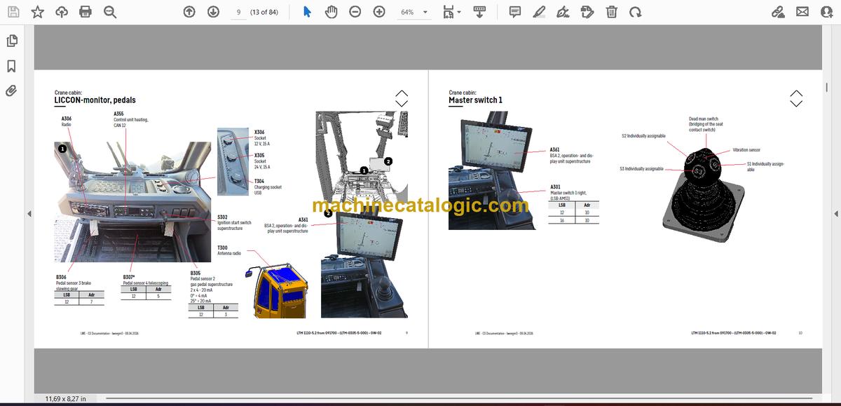
- LICCON-monitor, pedals
- Master switch 1
- Master switch 2, control unit arm rest
- Control unit side window
- Interior furnishing – driver seat, side console
- Interior furnishing – radio, immobiliser*
- Sliding door – door contact, locking system
- Wiper motor, washer pump
- Heating – temperature sensors
- Heater – heat exchanger
- Heating – Thermo Pro 90
- Air-conditioner
- LMB – warning device (EN 13000)
- Platform
- Switch cabinet:
- LSB-board, voltage converter, heating control unit
- Relay, resistor module, earth distribution
- Multi input and output module, diagnosis plug, fan
- Emergency operation – XNOT-plug
- EMERGENCY OPERATION – resistors
- Crane drive:
- Crane hydraulic:
- Overview – hydraulic left
- Metering connector plate
- Activation slewing gear (up to 091839)
- Analog pilot control slewing gear (from 091840)
- Slewing brake
- Auxiliary consumer valves
- Locking slewing platform
- Oil cooler, oil filter
- Telescoping
- Overview – hydraulic right
- Main control block – activation with EHA (up to 091839)
- Main control block – activation with EHA (up to 091839)
- Main control block – Pressure stages at telescoping (up to 091839)
- Main control block – analog pilot control (from 091840)
- Main control block – analog pilot control (from 091840)
- Hydraulic pumps, temperature switch hydraulic oil
- Hoist gear 1
- Hoist gear 2*
- Slewing gear
- Luffing gear
- Ballasting right
- Ballasting left
- Ballasting- ballast recognition
- Ballasting- ballast recognition
- Telescoping cylinder – pretension
- Oil tank, oil cooler*
- Tilting cab, oil preheating
- Telescoping boom:
- Electric – working flood light
- Electric – length sensor
- Electric- cable drums and length sensors
- Electric – boom head
- Telematic- position sensor
- Telematic- tele section pinning
- Telematic – gripper pinning, position sensor
- Emergency operation – tele- and gripper pinning
- Special equipment*:
- Crane hydraulic – emergency operation*
- Crane hydraulic- activation luffing swing-away jib*
- Transport device – hydraulic*
- Hydraulic double swing-away jib – hydraulic*
- Hydraulic double swing-away jib – angle sensor, hoist limit switch
- Mechanical double swing-away jib – angle sensor, hoist limit switch
- Erection jib – hoist limit switch, angle sensor*
- Winch sensor, obstruction light*
- Dolly operation* – additional hydraulics (until 091839)
- Dolly operation* – additional hydraulics (from 091840)
- Camera monitoring – slewing platform*
- Camera monitoring – tele boom*
- Attachment:
- Index
- Technical terms and abbreviations
- Limitation of liability / Disclaimer
Liebherr Crane


