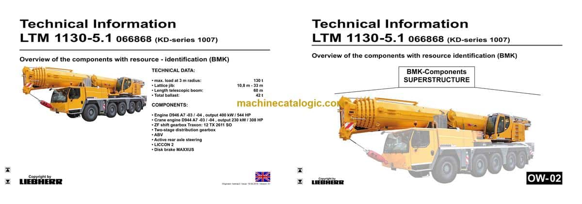
The Liebherr LTM 1130-5.1 Mobile Crane is a serious lift machine that earns its keep on tight jobsites, so knowing exactly where every relay, valve, and sensor sits matters when it’s down. The Technical Information & BMK Components Manual (component identification) is what your techs reach for when a wiring diagram calls out “K15” or “V23” and they need to find it on the actual crane. In a busy workshop, this is what keeps diagnostics moving instead of burning time hunting parts. It covers the machine layout for SN 066896, both carrier and superstructure, so you can plan work and parts flow with fewer surprises.
What this manual helps you do
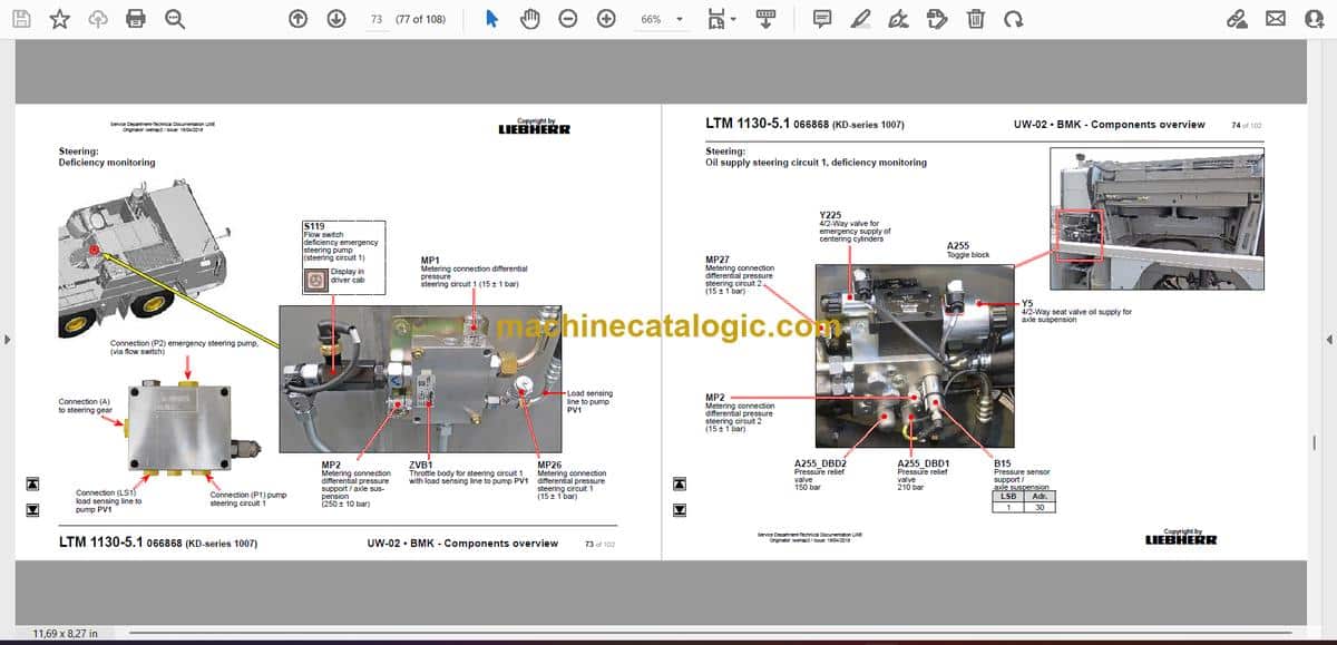
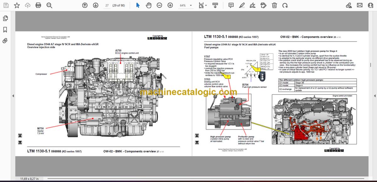
- Identify which physical component matches a reference like E1, K3, or X45 from the wiring or hydraulic diagrams.
- Locate the exact mounting position of sensors, relays, valves, and control units on the carrier and superstructure.
- Trace harness routes and component groupings using outline and overlay views of the crane.
- Cross-reference Liebherr component IDs to other documentation so fault codes and schematics tie to real hardware.
- Pinpoint what Liebherr actually calls a component so you can order or discuss it correctly with parts or service.
Who this is for
This is for workshop technicians, field service techs, electrical diagnostic engineers, fleet mechanics, and training instructors building layout knowledge. If you need repair procedures, torque specs, or part numbers, you want the service manual and parts catalogue instead.
FAQ
Q: Are the diagrams clear and searchable?
A: Yes, this is a PDF with clear component layout diagrams you can zoom and text-search for BMK IDs and terms.
Q: Does it cover both the carrier and the upper crane structure?
A: Yes, it combines BMK information for the carrier (chassis/undercarriage) and the superstructure into one document.
Q: Does it work alongside other Liebherr manuals?
A: Yes, the BMK references are meant to be used with Liebherr wiring diagrams, hydraulic schematics, service manuals, and parts catalogues.
Bottom line: If your goal is fast, accurate component identification on an LTM 1130-5.1, this is the right manual; if you want how-to repair steps or part numbers, it’s not.
📘 Show Index
Table of Contents:
Superstructure — Table of Contents
- Oberwagen allgemein:
- Beleuchtung Drehbühne
- Beleuchtung Ausleger
- LMB-Warneinrichtung (EN 13000)
- Zentralschmieranlage
- Kranelektrik:
- Krankabine:
- Heizung – Heizklimagerät
- Heizung – Ansteuerung, Temperatursensoren
- Wischermotoren, Waschpumpe
- Innenausstattung, Bedienelemente Seitenkonsole
- Podest Kabine
- Armaturen Kabine:
- Liccon-Monitor, Pedale
- Meisterschalter, LSB-TE1 rechts
- Meisterschalter, LSB-TE2 links
- Bedien- und Kontrolleinheit
- Schaltschrank Krankabine:
- Schwenkrahmen – Sicherungen
- Relais, Widerstandsmodul
- Montageblech – LSB-Master, Spannungswandler
- Universelles Ein-/Ausgabe Modul UEA – Datenlogger II
- Diagnosestecker, Ferndiagnose
- Steckerblech Drehbühne / Kabine
- NOTBETRIEB – XNOT-Stecker
- NOTBETRIEB Widerstände
- Dieselmotor D944 A7 Stufe IV SCR und IIIA-Derivat eAGR
- Einbauansicht
- Motorsteuergerät
- Übersicht Einspritzseite
- Kraftstoffpumpen
- Kraftstoff-Niederdrucksensoren
- Liebherr Daisy-Chain Diesel-Einspritzsystem
- Injektoren LCR-I S2
- Übersicht Abgasseite
- Ladeluft-Sensoren und -Vorwärmung
- Abgasklappe
- Abgasturbolader mit Wastegate
- Übersicht Schwungradseite und Generator
- Drehzahlsensoren
- Übersicht Lüfterseite
- Kühlmittel, Temperatursensor Kühlmittel und Außentemperatur
- Ölkreislauf
- Abschlusswiderstand CAN-LIDEC (ECU-CAN2)
- Abschlusswiderstand Motor-CAN (ECU-CAN2)
- Nur Stufe IIIA-Derivat-Motoren
- Externe Abgas-Rückführung eAGR
- Intercooler Temperatur-Sensor
- Abgasnachbehandlung SCR
- Übersicht Abgasanlage
- Harnstofftank und Tanksonde
- Pumpen-Modul und AdBlue-Leitungen
- AdBlue-Injektor und Upstream-Sensoren
- Downstream-Sensoren
- Umgebungsluftsensor und Abgasklappe
- Luftfilteranlage bei Motor 3a-Derivat
- Druckluftanlage Oberwagen:
- Luftpresser, Lufttrockner
- Diesel Kraftstoffanlage:
- Kraftstoff-Vorfiltereinheit, Handförderpumpe
- Kraftstofftank und Tankgeber
- Kühlanlage:
- Kühler-Lüfterantrieb
- Kühlmittel-Niveaugeber
- Kranhydraulik:
- Übersicht Hydraulikpumpen
- Übersicht Hydraulikkomponenten
- Übersicht Messanschlussplatte
- Hauptsteuerblock
- Hauptsteuerblock – Druckstufenventile und Druckgeber
- Teleskopzylinder – Vorspannung
- Drehwerk – Ansteuerung, Bremse
- Drehwerk – Ausleger-Richtung
- Wippwerk
- Hubwerk 1
- Hubwerk 2*
- Hilfsverbraucher, Drehbühnenarretierung
- Vario Ballast – Ballastierung rechts
- Vario Ballast – Ballastierung links
- Ballastüberwachung
- Temperaturgeber und Ölkühler
- Teleskopausleger:
- Anlenkstück, „Ausleger steil“
- Auslegerkopf
- Ausschubmechanik (Telematik) – Televerbolzung
- Ausschubmechanik (Telematik) – Zylinderposition
- Notbetrieb Tele- / Zylinderverbolzung
- Sonderausstattung:
- Klappspitze* – Elektrik
- Klappspitze* – Hydraulik
- Wegfahrsperre*
- Zusatzheizung Thermo Pro 90
- Klimaanlage*
- Dolly* (Anhänger für Ausleger-Transport USA)
- Notbetätigung Kranhydraulik*
- Index
Liebherr Crane


