The Liebherr LTM 1150-5.3 Mobile Crane is a high-end all-terrain machine, and when it stops, your schedule and cost per lift go sideways fast. The BMK / Technical Information manual is what your techs reach for when they’re standing at the crane with a fault on the screen and a schematic in their hand. Component identification is what keeps diagnosis tight, parts orders correct the first time, and field visits down to a single trip. If you mainly need to know “Where is this thing and what does Liebherr call it?”, this is the right document.
What this manual helps you do
- Identify where each electrical, hydraulic, and mechanical component sits on the LTM 1150-5.3 by using outline views of carrier and superstructure.
- Locate physical components on the crane that match schematic tags like E…, K…, V…, or X… from Liebherr wiring or hydraulic diagrams.
- Trace reference designators from a fault code or circuit diagram to the exact box, valve, sensor, or connector on the machine.
- Cross-reference Liebherr’s internal component IDs with other documentation so you can then jump to the right service or parts information.
- Pinpoint items during planning or training so new technicians learn the layout before they start pulling covers and wasting time.
Who this is for
This suits workshop technicians, field service techs, electrical diagnostic engineers, fleet mechanics, and training instructors who already use Liebherr schematics. If you need repair steps, settings, or orderable part numbers, you want the service manual or parts catalogue instead, not this BMK.
FAQ
Q: Are the diagrams clear and searchable in PDF?
A: Yes, this type of BMK manual is supplied as a readable PDF with clear component outlines that you can zoom and search by ID tag.
Q: Does it cover both carrier and superstructure for SN 079777?
A: Yes, it combines BMK information for the carrier (chassis/undercarriage) and the superstructure (upper crane) for that serial number reference.
Q: Does it tie in with other Liebherr manuals I already have?
A: Yes, the BMK component identification links the physical crane to wiring diagrams, service literature, and parts catalogues by using the same reference designators.
Bottom line: If your main pain is “Where is K15 on this LTM 1150-5.3 and what is it?”, this BMK manual is exactly what you need; if you want how-to-repair or what-to-order, it’s not.
📘 Show Index
Table of Contents:
Carrier — Table of Contents
- Table of contents
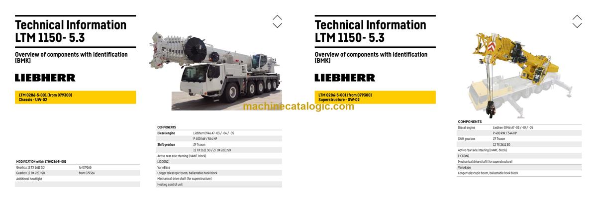
- Chassis:
- View from front, lighting and mirror
- View rear, lighting
- Vehicle lighting right
- Vehicle lighting left
- Warning signal sensor, air pressure connection / front
- Trailer coupling*, air pressure connection, warning signal sensor / rear
- Plug connection, voltage converter
- Earth- and distributor connector in the wiring loom – W7
- Earth- and distributor connector in the wiring loom – W6
- Control elements
- BTB, remote control module – BTT
- Control elements centre console
- Driver cab:
- Doors and windows, interior lighting
- Screen wiper and – washer
- Heating – ventilation and heat exchanger
- Air-conditioner
- Wiring loom – back-up camera, radio
- Centre console – battery, main switch, fuse box
- Center console – I/O modules, BTB
- Centre console – fuses
- Centre console – relay
- Centre console – relay
- Centre console – voltage converter, activation heating flange
- Centre console – control unit ABV, components
- Centre console – fan, component carrier, Emergency STOP
- Centre console – diagnosis plug
- Telemetry FMS-interface
- Pneumatic system:
- Air compressor and air dryer
- Compressed air reservoir
- Pneumatic valves in the driver cab
- Brake relay- and overload protection valve
- Filter and overflow valve, measuring points compressed air circuits
- Solenoid valve for auxiliary consumer
- Pressure sensors and pressure switches
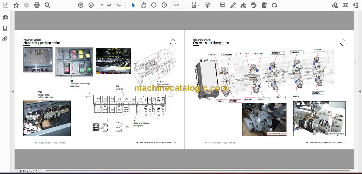
- Monitoring parking brake
- Disk brake system:
- Overview – brake system
- Overview – brake pad monitoring
- Brake pad monitoring display
- ABV control valve
- ABV wheel speed sensors
- Hill start assist
- Drive assembly:
- Installation view
- Diesel engine – installation
- Diesel engine D946 A7 -03 (eAGR) 04 (SCR) / -05 (SCRF):
- Engine control unit
- Overview injection side
- Fuel pumps
- Fuel low pressure sensors
- Liebherr diesel injection system Daisy Chain
- Injectors LCR-I S2
- Type plates:
- Overview exhaust gas side
- Charge air sensors and charge air preheating
- Exhaust gas flap
- Exhaust gas turbo charger with wastegate
- Overview flywheel side and generator
- Speed sensors
- Overview fan side
- Coolant, temperature sensor coolant and ambient temperature
- Oil circuit
- Terminal resistor CAN-LIDEC (ECU-CAN2)
- Terminal resistor engine-CAN (ECU-CAN2)
- External exhaust gas return eAGR
- Intercooler temperature sensor
- Exhaust gas system – exhaust after treatment SCRonly:
- Overview
- AdBlue-injector and upstream-sensors
- Downstream sensors
- Overview
- AdBlue-injector and upstream-sensors
- Downstream sensors
- Urea tank and urea tank sensor
- Pump module and AdBlue-lines
- Air filter system:
- Air filter-vacuum, air flap
- Diesel fuel system:
- Cooling system:
- Cooler – fan drive, level sensor
- Automatic shift gearbox to 079365:
- ZF TraXon 12 TX 2611 SO (intarder 3)
- ZF TraXon Intarder 3, clutch actuation unit (ConAct)
- Automatic shift gearbox from 079366:
- ZF TraXon DynamicPerform 12 DX 2611 SO – gearbox control
- ZF TraXon DynamicPerform 12 DX 2611 SO – Intarder
- ZF TraXon DynamicPerform 12 DX 2611 SO – wet starting clutch
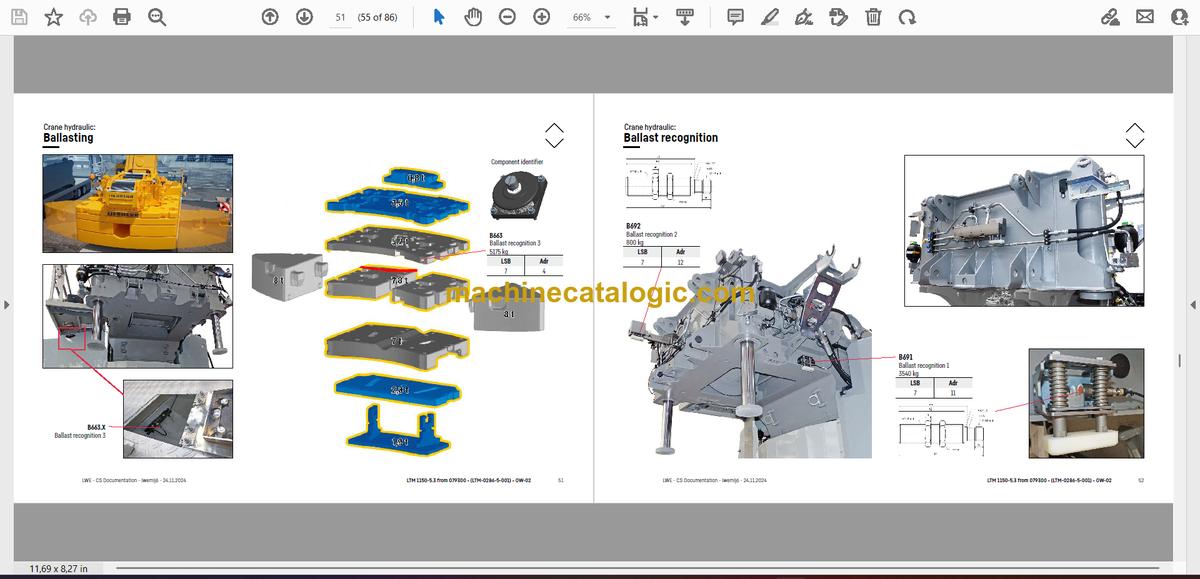
- Hydraulic:
- Temperature sensor hydraulic oil, hydraulic oil tank
- Hydraulic pumps – overview
- Fan valve, pretension centering pressure
- Drive train:
- Overview
- Distribution gearbox Kessler VG 2700 (two stage)
- Road-/ offroad gear – switching
- Travel drive / crane drive (PTO) – switching
- Crane drive
- Transverse differential lock axle 1, longitudinal differential lock distribution gear
- Transversal differential lock axle 2, activation axle 1*
- Long. and transv. differential lock axle 4 and 5
- Transverse differential lock axle 5
- Steering:
- Steering from superstructure
- Steering gear ZF-Servocom
- Oil supply steering circuit 1, deficiency monitoring
- Oil supply steering circuit 2
- Active rear axle steering:
- CAN-Valves (HAWE)
- Control block
- Valve block
- Oil filter
- Angle sensor
- Steering- and centering cylinder, safety valves
- Support:
- Inclination sensor
- Support valves – right
- Support valves – left
- Extension cylinder
- Sliding beam monitoring
- Support cylinder
- Monitoring support pressure
- Axle suspension:
- Level sensor- axle suspension
- Valve block – axle suspension right
- Valve block – axle suspension left
- Switch over diaphragm reservoir*
- Special equipment:
- Brake force reduction axle 1 and 2
- Brake force reduction axles 3 to 5
- Eddy currant brake Telma Focal 2200*
- Additional heating – Thermo Pro 90
- Additional heating – Air Top 2000 ST*
- Additional heating – engine pre-heating*
- External power supply
- Back-up camera*
- Battery charger
- Hydraulic emergency control
- Attachment:
- Index
- Limitation of liability / Disclaimer
Liebherr Crane


