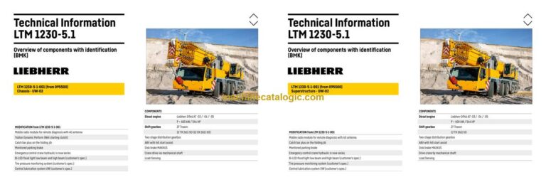
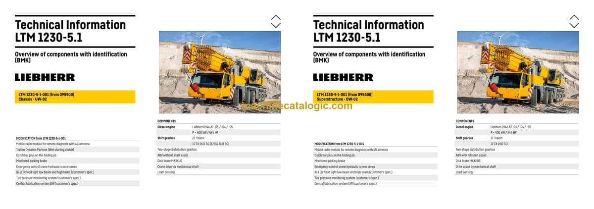
The Liebherr LTM 1230-5.1 Mobile Crane is a high-end all-terrain crane, and when it’s down on a remote job, every minute costs money. The BMK / component identification manual is what techs and electricians reach for when they’re standing at the crane with a laptop or tablet, trying to match what’s on a wiring or hydraulic diagram to the actual iron and harnesses in front of them. Component identification matters because if you can’t find “K15” or “V12” quickly, you’re wasting time just hunting around the machine instead of fixing the fault. This Technical Information & BMK Components Manual for SN 095597 is built for exactly that kind of work.
What this manual helps you do
- Identify which physical component matches a schematic tag like E1, K3, X45, or V12 on the LTM 1230-5.1.
- Locate sensors, valves, relays, junction boxes, and harness plugs on both carrier and superstructure using outline diagrams.
- Trace wiring or hydraulic references from Liebherr schematics to their real-world mounting points on the crane.
- Cross-reference Liebherr component IDs with where they appear in other factory manuals and fault lists.
- Pinpoint component locations when training new techs so they learn the crane layout without guesswork.
Who this is for
This is for a workshop technician, field service tech, electrical diagnostic engineer, fleet mechanic, or training instructor who already has service data and schematics. If you need repair procedures, torque specs, or part numbers, you want a service manual or parts catalogue instead, not this BMK.
FAQ
Q: Is the PDF clear and searchable enough to zoom in on diagrams?
A: Yes, these BMK PDFs are usually set up so you can zoom and search component IDs, and the layout views are meant to be read on-screen.
Q: Does it cover both the carrier and the upper crane body?
A: Yes, this product combines BMK component identification and layout information for both the carrier and the superstructure of the LTM 1230-5.1.
Q: Will it work alongside my Liebherr wiring diagrams and parts catalogue?
A: Yes, that’s exactly the point; the BMK manual ties the reference designators in your wiring, hydraulic, and parts documents to their physical locations on the crane.
Bottom line: If you need to find components on the machine and match them to Liebherr reference IDs, this is the right manual. If you’re after how to repair or which part to order, this is not what you need.
📘 Show Index
Table of Contents:
Carrier — Table of Contents
- Table of contents
- Chassis:
- Lighting front and mirrors
- Lighting rear
- Side marker lights right
- Side marker lights left
- Sockets, warning signal sensor
- Back-up camera
- Driver cab:
- Doors and windows, interior lighting
- Screen wiper and – washer, heating valves
- Ventilation and heat exchanger
- Control elements, seats
- BTB, remote control module BTT
- Control elements centre console
- Telemetry FMS-interface
- Telemetry-modem, monitoring parking brake
- Driver cab – centre console:
- I/O- modules, BTB and voltage supply
- Batteries and battery main switch
- Fuses
- Relays
- Voltage converter, heating flange control
- Components, control unit
- Fan, component carrier, EMERGENCY STOP
- Diagnosis plug
- Air-conditioner:
- Overview electrical components
- Pneumatic system:
- Air compressor and air dryer
- Compressed air reservoir, trailer control valve*
- Pneumatic valves in the driver cab
- Brake relay- / overload protection valve
- Overflow valve, metering points compressed air circuits
- Pressure sensor and pressure switch for axle suspension and brake system
- Solenoid valves auxiliary consumer
- Overview disk brake system
- Overview brake pad monitoring
- Brake pad monitoring indicator
- ABV – Regulating valves/ hill start assist
- ABV – wheel speed sensors
- Drive assembly:
- Complete unit installation view
- View from right
- View from left
- Diesel engine D946 A7 -03 (eAGR) / -04 (SCRonly) / -05 (SCRF):
- Engine control unit
- Overview injection side
- Fuel pumps
- Fuel low pressure sensors
- Liebherr Daisy-Chain diesel injection system
- Injectors LCR-I S2, type plate
- Overview exhaust gas side
- Charge air sensors and -preheating
- Exhaust gas flap
- Exhaust gas turbo charger with wastegate
- Overview flywheel side and generator
- Speed sensors
- Overview fan side
- Cooling agent
- Oil circuit
- Ambient temperature diesel engine
- Terminal resistor CAN-LIDEC (ECU-CAN2)
- Terminal resistor engine-CAN (ECU-CAN2)
- Diesel engine D946 A7 -03 (eAGR) / Power Band H:
- External exhaust gas return eAGR
- Intercooler temperature sensor
- Exhaust gas system “SCRonly”:
- Overview
- AdBlue-injector and upstream-sensors
- Downstream sensors
- Exhaust gas system “SCRF”:
- Overview
- AdBlue-injector and upstream-sensors
- Downstream sensors
- Exhaust after treatment SCRonly / SCRF:
- Urea tank and tank sensor
- Pump module and AdBlue-lines
- Exhaust gas system
- Components diesel engine:
- Air filter system
- Diesel fuel system
- Cooling system
- ZF – shift gearbox Traxon 12 TX 2611 SO:
- ZF shift gearbox Traxon Dynamic Perform 12 DX 2611 SO:
- Gearbox control
- Intarder
- Wet starting clutch
- Hydraulic supply:
- Overview hydraulic pumps
- Support and axle suspension
- Temperature sensor hydraulic oil, hydraulic oil reservoir
- Return filter leak oil
- Emergency control crane hydraulic – vehicle
- Emergency control crane hydraulic – support
- Drive train:
- Overview
- Distribution gear – Kessler VG 2700 (2-stage)
- Road/off-road switchover
- Switch over travel drive / crane drive (PTO)
- Crane drive
- Crane drive – angle gear box
- Transversal differential lock axle 2 and 3*
- Transversal differential lock axle 4 and 5
- Longitudinal differential lock and activation* axle 3
- Steering:
- Steering gear ZF-Servocom
- Oil supply steering circuit 1
- Oil supply steering circuit 2
- Active rear axle steering:
- Flow and pressure monitoring
- CAN-valves
- Control block
- Measuring points
- Angle sensor
- Steering- and centering cylinder, safety valves
- Support:
- Inclination sensor
- Support valves – right
- Support valves – left
- Sliding beam sliding beam front
- Sliding beam sliding beam rear
- Support cylinder
- VarioBase
- Sliding beam monitoring
- Axle suspension:
- Level sensor- axle suspension
- Pneumatic valves for axle suspension
- Valve block – axle suspension right
- Valve block – axle suspension left
- Axle suspension cylinder
- Special equipment:
- Eddy currant brake Telma Focal 2200*
- Additional heating Thermo Pro 90*
- Additional heating Air Top 2000 and fuel tank*
- Cooling water preheating*
- External power supply 110 V / 230 V*
- Engine preheating*
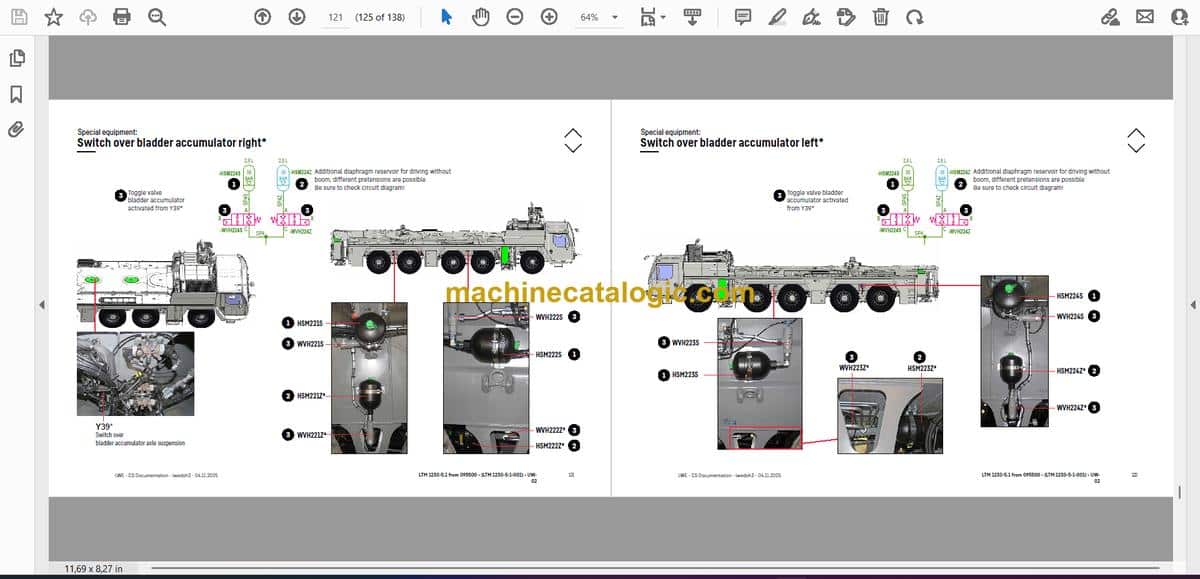
- Switch over bladder accumulator right*
- Switch over bladder accumulator left*
- Brake force reduction axle 1 and 2*
- Brake force reduction axles 3 to 5*
- Battery charger*
- Tire pressure monitoring system*
- Lifting axle 3* / axle compensation
- Additional floodlight sidewise and rear*
- Central lubrication system*
- Attachment:
- Index
- Limitation of liability / Disclaimer
Superstructure — Table of Contents
- Inhaltsverzeichnis
- Oberwagen allgemein:
- Beleuchtung Drehbühne
- Beleuchtung Ausleger
- LMB-Warneinrichtung (EN 13000)
- Zentralschmieranlage
- Krankabine:
- Heizung – Heizklimagerät
- Heizung – Zusatzheizung Thermo Pro 90
- Heizung – Ansteuerung, Temperatursensoren
- Klimaanlage
- Wischermotoren, Waschpumpe
- Innenausstattung
- Podest Kabine
- Armaturen Kabine:
- LICCON-Monitor, Pedale
- Meisterschalter 1, LSB-TE1 rechts
- Meisterschalter 2, LSB-TE2 links
- Bedien- und Kontrolleinheit
- Schaltschrank Krankabine:
- Schwenkrahmen – Sicherungen
- Relais, Widerstandsmodul
- Montageblech – LSB-Master, Spannungswandler
- Universelles Ein- und Ausgabemodul UEA, Datenlogger II
- Diagnosestecker, Ferndiagnose
- NOTBETRIEB – XNOT-Stecker
- NOTBETRIEB Widerstände
- Kranantrieb:
- Mechanische Welle
- Winkelgetriebe
- Verteilergetriebe
- Kranhydraulik:
- Übersicht Hydraulikpumpen
- Übersicht Hydraulikkomponenten
- Übersicht Messanschlussplatte
- Hauptsteuerblock, Druckspitzenventil
- Druckgeber, Überwachung Hauptschieber
- Teleskopzylinder – Vorspannung
- Drehwerk – Ansteuerung, Bremse
- Drehwerk
- Drehkranzgeber
- Wippwerk
- Hubwerk 1
- Hubwerk 2*
- Hubwerk 2* – Anschlüsse
- Ventilblock Nebenverbraucher
- Kippzylinder Kabine, Drehbühnenarretierung
- VarioBallast: Ballastierung links
- VarioBallast: Ballastierung rechts
- Temperaturgeber und Ölkühler
- Ölfilter
- Notbetätigung Kranhydraulik
- Notbetätigung Kranhydraulik
- Teleskopausleger:
- Anlenkstück
- Auslegerkopf
- Ausschubmechanik (Telematik) – Zylinderposition, Teleteilverbolzung
- Ausschubmechanik (Telematik) – Zylinderverbolzung
- Teleskopverbolzung / Zylinderverbolzung
- Sonderausstattung:
- Klappspitze* – Elektrik
- Klappspitze* – Hydraulik
- Hydraulische Klappspitze* – Schlauchtrommel
- Hydraulisch verstellbare feste Gitterspitze TF*
- Dollybetrieb Drehbühne rechts*
- Dollybetrieb Drehbühne links*
- Kameraüberwachung*
- Wegfahrsperre*
- Ölvorwärmung*
- Anhang:
- Index
- Haftungsbegrenzung / Disclaimer
- Table of contents
- Superstructure general:
- Lighting slewing platform
- Lighting boom
- LMB – warning device (EN 13000)
- Central lubrication system
- Crane cabin:
- Heating – heating air conditioning
- Heating – additional heating Thermo Pro 90
- Heating – activation, temperature sensors
- Air-conditioner
- Wiper motor, washer pump
- Interior furnishing
- Platform cab
- Fittings cab:
- LICCON-monitor, pedals
- Joystick 1, LSB-TE1 right
- Joystick 2, LSB-TE2 left
- Operation- and control unit
- Switch cabinet crane cabin:
- Tilting frame – fuses
- Relays, resistor modules
- Mounting plate – LSB-master, voltage converter
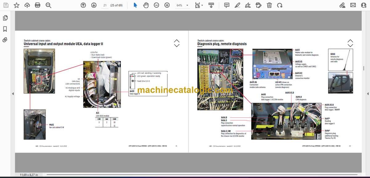
- Universal input and output module UEA, data logger II
- Diagnosis plug, remote diagnosis
- EMERGENCY OPERATION – XNOT-plug
- EMERGENCY OPERATION resistors
- Crane drive:
- Mechanical shaft
- Angle gear box
- Distribution gearbox
- Crane hydraulic:
- Overview hydraulic pumps
- Overview hydraulic components
- Overview metering connector plate
- Main control block,
pressure peak valve
- Pressure sensor, monitoring main slide
- Telescope cylinder – pretension
- Slewing gear – activation, brake
- Slewing gear
- Slewing ring sensor
- Luffing gear
- Hoist gear 1
- Hoist gear 2*
- Hoist gear 2* – connections
- Valve block auxiliary consumer
- Cab tilt cylinder, locking slewing platform
- Vario ballast: Ballasting left
- Vario ballast: Ballasting right
- Temperature sensor and oil cooler
- Oil filter
- Emergency control crane hydraulic
- Emergency control crane hydraulic
- Telescoping boom:
- Base section
- Boom head
- Extension mechanics (Telematic) – cylinder position, tele section pinning
- Extension mechanics (Telematic) – cylinder pinning
- Telescope pinning / cylinder pinning
- Special equipment:
- Swing away jib* – electric
- Swing away jib* – hydraulic
- Hydraulic swing-away jib* – hose drum
- Hydraulically adjustable fixed lattice jib TF*
- Dolly operation slewing platform right*
- Dolly operation slewing platform left*
- Camera monitoring*
- Immobiliser*
- Oil preheating*
- Attachment:
- Index
- Limitation of liability / Disclaimer
- Índice
- Generalidades sobre el equipo giratorio:
- Iluminación de plataforma giratoria
- Iluminación de la pluma
- Dispositivo de advertencia de LMB (EN 13000)
- Sistema de lubricación central
- Cabina de la grúa:
- Calefacción: climatizador
- Calefacción: calefacción auxiliar Thermo Pro 90
- Calefacción: activación y sensores de temperatura
- Climatizador
- Motores de limpiaparabrisas y bomba de lavado
- Equipamiento interior
- Base de la cabina
- Mandos de cabina:
- Monitor LICCON, pedales
- Interruptor maestro 1, LSB-TE1 lado der.
- Interruptor maestro 2, LSB-TE2 lado izq.
- Unidad de mando y control
- Armario de distribución de cabina de grúa:
- Chasis pivotante: fusibles
- Relés y módulo de resistencias
- Chapa de montaje: maestro de LSB y transformador de tensión
- Módulo universal de entradas/salidas UEA y registrador de datos II
- Conector de diagnóstico, diagnóstico remoto
- FUNCIONAM. DE EMERGENCIA: conector XNOT
- Resistencias de FUNCIONAM. EMERGENCIA
- Accionamiento de grúa:
- Árbol mecánico
- Engranaje angular
- Caja de transmisión
- Sistema hidráulico de la grúa:
- Vista general de bombas hidráulicas
- Vista general de componentes hidráulicos
- Vista general de la placa de conexiones de medición
- Bloque de mando principal y válvula de picos de presión
- Transmisores de presión y control de corredera principal
- Cilindro telescópico: tensión previa
- Mecanismo de giro – Activación y freno
- Mecanismo de giro
- Codificador de corona giratoria
- Mecanismo de basculación
- Mecanismo de elevación 1
- Mecanismo de elevación 2*
- Mecanismo de elevación 2*: conexiones
- Bloque de válvulas de consumidores auxiliares
- Cilindro basculante de cabina y bloqueo de la plataforma giratoria
- Lastre Vario: Lastrado, lado izq.
- Lastre Vario: Lastrado, lado der.
- Transmisor de temperatura y radiador por aceite
- Filtro de aceite
- Accionamiento de emergencia de sist. hidráulico de grúa
- Accionamiento de emergencia de sist. hidráulico de grúa
- Pluma telescópica:
- Pieza de articulación
- Cabezal de la pluma
- Mecanismo de empuje vertical (sist. telem.): posición de cilindro y embul. tramo telesc.
- Mecanismo de empuje vertical (sistema telemático): embulonado de cilindro
- Embulonado de tramo telescópico / embulonado de cilindro
- Equipamiento especial:
- Punta rebatible*: sistema eléctrico
- Punta rebatible*: sistema hidráulico
- Punta rebatible hidráulica*: tambor de manguera
- Punta de mástil en celosía TF fija regulable hidráulicamente*
- Servicio de carro Dolly en plataforma giratoria derecha*
- Servicio de carro Dolly en plataforma giratoria izquierda*
- Control de cámara*
- Bloqueo antirrobo*
- Precalentamiento de aceite*
- Anexo:
- Índice
- Limitación de responsabilidad / Disclaimer
- Table des matières
- Tourelle en général :
- Éclairage de la tourelle
- Éclairage de la flèche
- Avertisseurs CEC (EN 13000)
- Système de graissage centralisé
- Cabine de la tourelle :
- Chauffage : appareil de chauffage et climatisation
- Chauffage : chauffage add. Thermo Pro 90
- Chauffage : commande, capteurs de température
- Climatisation
- Moteurs d’essuie-glace, pompe de lave-glace
- Équipements intérieurs
- Marchepied de cabine
- Équipements de cabine :
- Écran LICCON, pédales
- Manipulateur 1, LSB-TE1 côté droit
- Manipulateur 2, LSB-TE2 côté gauche
- Unité de commande et de contrôle
- Armoire électrique dans la cabine de tourelle :
- Boîtier escamotable : fusibles
- Relais, module de résistance
- Plaque de montage : maître LSB, convertisseur de tension
- Module universel E/S (UEA), enregistreur de données II
- Connecteurs diagnostiques, télédiagnostic
- MODE D'URGENCE : connecteurs XNOT
- MODE D'URGENCE résistances
- Entraînement de grue :
- Arbre mécanique
- Réducteur angulaire
- Boîte de transfert
- Système hydraulique de la tourelle :
- Aperçu des pompes hydrauliques
- Aperçu des composants hydrauliques
- Aperçu de la plaque à raccords de mesure
- Bloc de commande principal, soupape des pics de pression
- Capteur de pression, surveillance du tiroir principal
- Vérin télescopique : précharge
- Mécanisme d'orientation : commande, frein
- Mécanisme d‘orientation
- Capteur de couronne
- Mécanisme de relevage
- Mécanisme de levage 1
- Mécanisme de levage 2*
- Mécanisme de levage 2* : raccords
- Bloc à soupapes des consommateurs auxiliaires
- Vérin de basculement de la cabine, blocage de rotation tourelle
- VarioBallast (lestage à rayon variable) : lestage gauche
- VarioBallast (lestage à rayon variable) : lestage droit
- Capteur de température et refroidisseur d'huile
- Filtre à huile
- Actionnement hydraulique d'urgence
- Actionnement hydraulique d'urgence
- Flèche télescopique :
- Élément de base
- Tête de flèche
- Méc. de déploiement (Telematik) – position du vérin, verrouillage des éléments tél.
- Mécanique de déploiement (Telematik) : verrouillage du vérin
- Verrouillage des éléments télescopiques / du vérin
- Équipements spéciaux :
- Fléchette pliante* : système électrique
- Fléchette pliante* : système hydraulique
- Fléchette pliante hydraulique* : tambour à flexible
- Fléchette treillis fixe TF à réglage hydraulique*
- Mode dolly de la tourelle à droite*
- Mode dolly de la tourelle à gauche*
- Surveillance vidéo*
- Antidémarrage*
- Préchauffage d’huile*
- Annexe :
- Index
- Limitation de responsabilité / Disclaimer
Liebherr Crane


