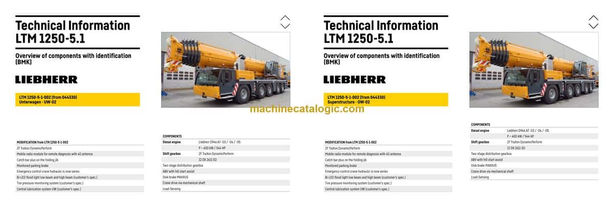
The Liebherr LTM 1250-5.1 Mobile Crane earns its keep on big lifts where downtime costs real money, so knowing exactly where every box, valve, and sensor sits matters. The BMK / Technical Information manual is what your techs grab when a fault code gives them “K15” or “V23” and they need to find it on the iron, not on paper. Component identification is what keeps you from burning an hour hunting for a relay buried in the carrier or a sensor tucked on the superstructure. I’ve seen more time lost from “where the hell is it?” than from the actual repair.
What this manual helps you do
- Identify which physical component matches a reference like E1, K3, or X45 from the wiring or hydraulic schematics.
- Locate sensors, valves, relays, junction boxes, and harnesses on both the carrier and superstructure using outline and layout views.
- Trace a fault code or schematic symbol to the exact spot on the crane so you know where to put your ladder, tools, and test gear.
- Cross-reference Liebherr’s internal component IDs to the correct area in your wiring diagrams, service info, or parts catalogue.
- Pinpoint components when training new techs so they learn the layout of the LTM 1250-5.1 without wandering around the machine.
Who this is for
This is aimed at workshop technicians, field service techs, electrical diagnostic engineers, fleet mechanics, and training instructors working on SN 044494 and similar. If you’re after repair procedures, torque specs, or orderable part numbers, you want a service manual and a parts catalogue instead.
FAQ
Q: Is the PDF clear and searchable enough to use on a laptop or tablet in the shop?
A: Yes, these BMK PDFs are usually clean, zoomable diagrams that you can search by component ID.
Q: Does this cover both the carrier and the upper crane body?
A: Yes, this BMK combines carrier and superstructure component identification for the LTM 1250-5.1.
Q: Does it tie in with other Liebherr manuals?
A: Yes, the component IDs are meant to match what you see in Liebherr wiring diagrams, hydraulic schematics, and parts books.
Bottom line: If your main problem is “I know the code or symbol, but I don’t know where the part is,” then yes—this is exactly the manual you need. If you want how-to repair steps or part numbers, then no, this isn’t the right book on its own.
📘 Show Index
Table of Contents:
Carrier — Table of Contents
- Table of contents
- Chassis:
- Lighting front and mirrors
- Lighting rear
- Side marker lights right
- Side marker lights left
- Sockets, warning signal sensor
- Back-up camera
- Earth- / distributor connector in the wiring loom W6
- Earth- / distributor connector in the wiring loom W7 / W146*
- Driver cab:
- Doors and windows, interior lighting
- Screen wiper and – washer, heating valves
- Ventilation and heat exchanger
- Control elements, seats
- BTB, remote control module BTT
- Control elements centre console
- Telemetry FMS-interface
- Telemetry-modem, monitoring parking brake
- Driver cab – centre console:
- I/O- modules, BTB voltage supply
- Batteries and battery main switch
- Fuses
- Relays
- Voltage converter, heating flange – control
- Components, control unit
- Fan, EMERGENCY STOP
- Diagnosis plug
- Air-conditioner:
- Overview electrical components
- Pneumatic system:
- Air compressor and air dryer
- Compressed air reservoir, trailer control valve*
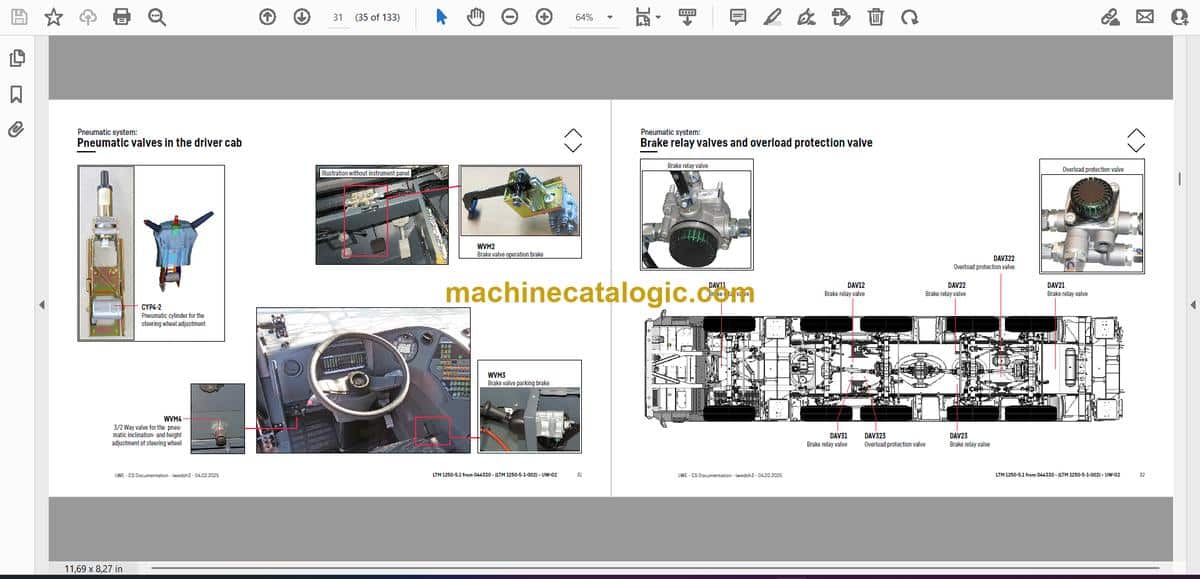
- Pneumatic valves in the driver cab
- Brake relay valves and overload protection valve
- Overflow valve, metering points compressed air circuits
- Pressure sensor and pressure switch for axle suspension and brake system
- Solenoid valves auxiliary consumer
- Overview disk brake system
- Overview brake pad monitoring
- Brake pad monitoring display
- ABV – Regulating valves / hill start assist
- ABV wheel speed sensors
- Drive assembly:
- Complete unit installation view
- View from right
- View from left
- Diesel engine D946 A7 -03 (eAGR) / -04 (SCRonly) / -05 (SCRF)
- Engine control unit
- Overview injection side
- Fuel pumps
- Fuel low pressure sensors
- Liebherr diesel injection system Daisy-Chain
- Injectors LCR-I S2, type plate
- Overview exhaust gas side
- Charge air sensors and charge air preheating
- Exhaust gas flap
- Exhaust gas turbo charger with wastegate
- Overview flywheel side and generator
- Speed sensors
- Overview fan side
- Cooling agent
- Oil circuit
- Ambient temperature diesel engine
- Terminal resistor CAN-LIDEC (ECU-CAN2)
- Terminal resistor engine-CAN (ECU-CAN2)
- External exhaust gas return eAGR
- Intercooler temperature sensor
- Exhaust gas system “SCRonly”
- Overview
- AdBlue-injector and upstream-sensors
- Downstream sensors
- Exhaust gas system “SCRF”
- Overview
- AdBlue-injector and upstream-sensors
- Downstream sensors
- Exhaust after treatment SCRonly / SCRF
- Urea tank and tank sensor
- Pump module and AdBlue-lines
- Exhaust gas system
- Components diesel engine:
- Air filter system
- Diesel fuel system
- Cooling system
- ZF-shift gear box TraXon DynamicPerform 12 DX 2611 SO:
- Gearbox control
- Intarder
- Wet starting clutch
- Hydraulic supply:
- Overview hydraulic pumps
- Support and axle suspension
- Temperature sensor hydraulic oil, hydraulic oil tank
- Emergency control crane hydraulic – vehicle
- Emergency control crane hydraulic – support
- Drive train:
- Overview
- Distribution gear – Kessler VG 2700 (2-stage)
- Road/off-road switchover
- Switch over travel drive / crane drive (PTO)
- Crane drive
- Crane drive – angle gear box
- Transversal differential lock axle 2 and 3*
- Transversal differential lock axle 4 and 5
- Longitudinal differential lock and activation* axle 3
- Steering:
- Steering gear ZF-Servocom
- Oil supply steering circuit 1, deficiency monitoring
- Oil supply steering circuit 2
- Active rear axle steering:
- Flow and pressure monitoring
- CAN-valves
- Control block
- Measuring points
- Angle sensor
- Steering- and centering cylinder, safety valves
- Support
- Inclination sensor
- Support valves – right
- Support valves – left
- Extension cylinder sliding beam
- Support cylinder
- VarioBase
- Sliding beam monitoring
- Axle suspension:
- Level sensor- axle suspension
- Pneumatic valves for axle suspension
- Valve block – axle suspension right
- Valve block – axle suspension left
- Axle suspension cylinder
- Special equipment:
- Eddy currant brake Telma Focal 2200*
- Additional heating Thermo Pro 90*
- Additional heating Air Top 2000 ST* and fuel tank*
- Engine preheating* Air Top EVO 55 / Thermo Top Pro 150
- Cooling water preheating*
- External power supply 110 V / 230 V*
- Compensation axle suspension*
- Switch over bladder accumulator right*
- Switch over bladder accumulator left*
- Braking force reduction*
- Battery charger*
- Central lubrication system*
- Additional floodlight sidewise and rear*
- Attachment:
- Index
- Limitation of liability / Disclaimer
Superstructure — Table of Contents
- Inhaltsverzeichnis
- Oberwagen allgemein:
- Beleuchtung Drehbühne
- Beleuchtung Ausleger
- LMB-Warneinrichtung (EN 13000)
- Zentralschmieranlage
- Krankabine:
- Heizung – Heizklimagerät
- Heizung – Zusatzheizung Thermo Pro 90
- Heizung – Ansteuerung, Temperatursensoren
- Klimaanlage
- Wischermotoren, Waschpumpe
- Innenausstattung
- Podest Kabine
- Armaturen Kabine:
- LICCON-Monitor, Pedale
- Meisterschalter 1, LSB-TE1 rechts
- Meisterschalter 2, LSB-TE2 links
- Bedien- und Kontrolleinheit
- Schaltschrank Krankabine:
- Schwenkrahmen – Sicherungen
- Relais, Widerstandsmodul
- Montageblech – LSB-Master, Spannungswandler
- Universelles Ein- und Ausgabemodul UEA, Datenlogger II
- Diagnosestecker, Ferndiagnose
- NOTBETRIEB – XNOT-Stecker
- NOTBETRIEB Widerstände
- Kranantrieb:
- Mechanische Welle
- Winkelgetriebe
- Verteilergetriebe
- Kranhydraulik:
- Übersicht Hydraulikpumpen
- Übersicht Hydraulikkomponenten
- Übersicht Messanschlussplatte
- Hauptsteuerblock
- Druckgeber und Stellungsüberwachung
- Teleskopzylinder – Vorspannung
- Drehwerk – Ansteuerung, Bremse
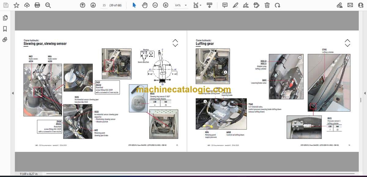
- Drehwerk, Drehwertgeber
- Wippwerk
- Hubwerk 1
- Hubwerk 2*
- Hubwerk 2* – Anschlüsse
- Ventilblock Nebenverbraucher
- Kippzylinder Kabine, Drehbühnenarretierung
- VarioBallast: Ballastierung links
- VarioBallast: Ballastierung rechts
- Ballastüberwachung
- Temperaturgeber und Ölkühler
- Ölfilter
- Notbetätigung Kranhydraulik
- Teleskopausleger:
- Anlenkstück
- Auslegerkopf
- Ausschubmechanik (Telematik) – Zylinderposition, Teleteilverbolzung
- Ausschubmechanik (Telematik) – Zylinderverbolzung
- Notbetrieb Tele- / Zylinderverbolzung
- Sonderausstattung:
- Klappspitze* – Elektrik
- Klappspitze* – Hydraulik
- Hydraulische Klappspitze* – Schlauchtrommel
- Kamera Winden*
- Hydraulisch verstellbare feste Gitterspitze TF*
- Dollybetrieb Drehbühne rechts*
- Dollybetrieb Drehbühne links*
- Ölvorwärmung*
- Wegfahrsperre*
- Anhang:
- Index
- Haftungsbegrenzung / Disclaimer
Liebherr Crane


