Link Belt 135 Tier3 Spin Ace Excavator Service Text Manual
Link Belt 135 Tier3 Spin Ace Excavator Service Text Manual
📘 Show Index
Link Belt 135 Tier3 Spin Ace Excavator Index:
Main body
Specifications
Overall
1. Main Data
2. Performance
3. Main Body Dimensions
4. Engine
5. Cooling System
6. Upper Side Work System
7. Operating Device
8. Swing Units
9. Travel Lower Body
Hydraulic Equipment
1. Hydraulic Device
2. Control Valve, Cylinder
Capacities, Filters
1. Coolant and Oil Capacities
2. Hydraulic Oil Filters
3. Fuel Filter
Lifting Capacity
Precautions for Lifting Loads with the Hydraulic Excavator
Lifting Capacities
Overall View
Overall View (135) (MONO BOOM SPEC.)
1. Standard Arm (2.39 m)
2. Long Arm (2.85 m)
Overall View (135) (MONO BOOM SPEC. WITH DOZER BLADE)
1. Standard Arm (2.39 m)
2. Long Arm (2.85 m)
Work Range Diagram
Work Range Diagram (135) (MONO BOOM SPEC.)
1. Standard Arm (2.39 m)
2. Long Arm (2.85 m)
Work Range Diagram (135) (MONO BOOM SPEC. WITH DOZER BLADE)
1. Standard Arm (2.39 m)
2. Long Arm (2.85 m)
Optional Components
Optional Components
Major Equipment Specifications
Equipment Configuration
Overall
Operator’s Cab
Lower Mechanism
Lower Assembly Diagram (overall)
Lower Assembly Diagram (overall) (WITH DOZER BLADE)
Lower Component
1. Travel Unit
2. Take-up Roller
3. Upper-roller
4. Lower-roller
5. Recoil Spring
6. Shoes
Upper Component
1. Swing Unit
Engine-related
1. Engine
2. Muffler
3. Air Cleaner (double element)
4. Radiator
Hydraulic Device
1. Hydraulic Pump
Control-related
1. Control Valve
2. Solenoid Valve (5 stack)
3. Remote Control Valve (left / right, travel operations)
4. Remote Control Valve Characteristic Diagram
5. Cushion Valve (heat circuit, with shuttle valve)
6. Selector Valve (option)
7. Center Joint
8. Solenoid Valve
Backhoe Attachment
1. Cylinder
2. Attachments
Sump Tank
Fuel Tank
2
Table of Contents
3 MST-15-01-001LX
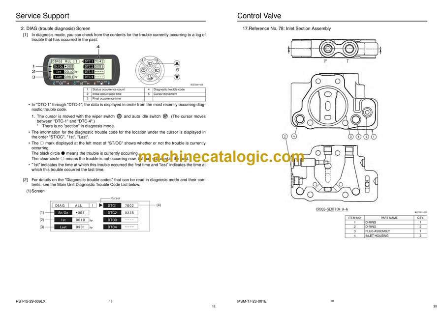
Hydraulic Section
Hydraulic Pump Operational Description
Structure and Operation Principle
Attached Drawing 1.
Pump Development Diagram
Attached Drawing 2.
Pump Structure Drawing
Control Valve Operation
When all Spools are in Neutral Position
1. Neutral Passage
2. Signal Passage
Independent Operations
1. Travel Spool Changeover
2. Extra Spool Changeover
3. Swing Spool Changeover
4. Bucket Spool Changeover
5. Boom Spool Changeover
6. Arm Spool Changeover
7. Parallel Throttle for Arm
8. Neutral Cut Spool Changeover (extra combination)
9. Blade Spool Changeover
10. Relief Valve
Compound Operation
1. Travel Compound Operation
2. Anti-drift Valve
Swing Unit
Swing Motor
Mechanical Brake
Make-up Valve
1. Explanation of Operation when Relief Valve is Pressurized
2. Explanation of Operation when Relief Valve is Depressurized
Swing Relief Valve
Anti-reverse Valve
Swing Reduction Gears
Problems and Remedies
Structural Drawings
Main Equipment Structure and Operation Explanation
Motor
1. Travel Motor
Hydraulic Circuit Section
Port Locations
Hydraulic Pump
Control Valve (MONO BOOM)
Control Valve (MONO BOOM with Blade)
Control Valve (OFFSET BOOM with Blade) (Option for Europe)
Pilot Hose Connection Diagrams
Pilot P & T Line
Pilot Control Line
Functional Description
List of Functions
Control Valve Configuration Table
Overview
Travel Circuits
High Speed Travel Circuit
Low Speed Travel Circuit
Straight Travel Circuit (simultaneous operation of travel forward and boom-up)
Swing Circuits
Swing Parking Circuit (independent operation of swing)
Swing Priority Variable Throttle Circuit
Arm Circuits
Arm-in / Arm-out 2-speed Circuit
Arm-in Load Holding Valve Circuit
Arm-in Forced Regenerative Circuit
Boom Circuits
Boom-up 2-speed Circuit
Boom-down Load Holding Valve Circuit
Boom-down Regenerative Circuit
Boom-down Windage Prevention Circuit
Option Circuits
Breaker and Crusher Circuit (2-speed confluence crusher circuit)
Breaker and Crusher Circuit (option line holding valve)
Breaker and Crusher Circuit (breaker circuit)
Secondary Option Shuttle Circuit
4
Table of Contents
5 MST-15-01-001LX
Electric Circuits Section
Wiring Diagrams
Electrical Components and Wiring for Upper Frame (Frame)
Electrical Components and Wiring for Cab
Air Conditioner
Electrical Components and Wiring for Upper Frame (Engine)
Electrical Components and Wiring for Upper Frame (Battery)
Electrical Components and Wiring for Upper Frame (Pump)
Harness Diagrams
Upper Frame
Frame Wiring Main Harness
Inside Cab
Cab Wiring Main Harness
Operational Description
Monitor Display
1. Monitor Switch Panel
2. List of Functions
Engine Control
1. Engine Start-up Control
2. Throttle Control
3. One-touch Idling
Monitor Output Control
1. 2-speed Travel
2. Swing Brake
3. Travel Alarm
4. Working Light
5. Windshield Wiper / Washer
6. Power Cut Delay
Monitor Display Control
1. Overheat Warning
2. Engine Oil Pressue Warning
3. Low Fuel Warning
4. Battery Charge Warning
5. Auto Preheat
6. Idle Up
7. Faulty Electrical System at Engine


