Link Belt 210LX Excavator Shop Manual
The Link Belt 210LX is a production excavator that spends its life in dirt, rock, and mud—digging foundations, loading trucks, trenching utilities. This shop manual is what I’d pull when I need to trace wiring, locate components, and plan a repair without tearing half the machine apart. If, for example, your boom won’t lift and I suspect an electrical issue, I’d use this to find the right relay and fuse in the battery compartment, verify power paths, and avoid guessing.
Applications & Use Cases
- Track down relay and fuse locations so you can quickly isolate electrical faults.
- Plan cab and exterior teardown so you only remove what’s necessary to reach a bad harness or switch.
- Verify component routing and mounting points before reassembly to prevent rub points and repeat failures.
- Use the location views to double-check that hoses, looms, and brackets are aligned and secured after a repair.
- Support field diagnostics by matching what you see on the machine to clear diagrams, reducing trial-and-error.
FAQ
Q: Can I use this manual on a tablet in the field?
A: Yes, it’s practical to keep it on a tablet or laptop so you can zoom in on diagrams while you’re at the machine.
Q: Is it worth printing sections of this manual?
A: Printing key pages you use often—like component locations—is handy for greasy jobs where you don’t want a device nearby.
Safety Note
Always lock out, tag out, and release stored energy before following any teardown or inspection steps from this manual.
Link Belt 210LX Excavator Index:
- 6004.pdf
- 4001.pdf
- General Location of Components (Outside the Cab) 6
- Relays and Main Fuses (Battery Compartment) 8
- General Location of Components (Inside the Cab) 9
- Fuse Box 11
- Instrument Panel 12
- H/S/L Mode Control 17
- Automatic Mode Control 18
- Acceleration Control 19
- Control of Engine Return to Idle (Automatic/Manual) 20
- Auxiliary Mode Control 21
- Automatic Engine Pre-heat 22
- Automatic Engine Warm-up 25
- 3) Diagram showing times 26
- Idle Control by Battery Voltage and Coolant Temperature 27
- Engine Emergency Stop 29
- Emergency Mode 31
- Lockout Functions 33
- Power Up 34
- Swing Brake 35
- Travel Speed 39
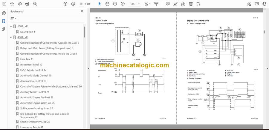
- Travel Alarm 42
- Supply Cut-Off Delayed 43
- Protection by Power Transistor 44
- Water Temperature Gauge 44
- Hydraulic Oil Temperature Gauge 46
- Fuel Level 47
- Engine Fuel Injection Pump Electronic Regulator 48
- Access to Control Screens 50
- Machine Condition 51
- Diagnostic Code 55
- Machine History 58
- Reset 61
- Message Display 64
- Prior Inspections 68
- Reading the Organization Charts 69
- Procedures 70
- Fuel 71
- Add Coolant Solution 72
- Low Engine Oil Pressure 73
- Overheating 74
- Battery Charge Circuit Defective 77
- Electrical System Troubleshooting 79
- Translation 83
- 5001.pdf
- Description 4
- Checking pin and bushing wear 12
- 5005.pdf
- Description 8
- Reconditioning 8
- Description 14
- Description 16
- Removal 16
- Notes
- 6003.pdf
- 8003.pdf
- Removal and installation 4
- Removal and installation 9
- Removal and installation 11
- Notes
- 8005.pdf
- Description 3
- Description 9
- 8006.pdf
- Removal and installation 3
- 8008.pdf
- 8012.pdf
- Boom cylinder description 4
- Arm cylinder description 6
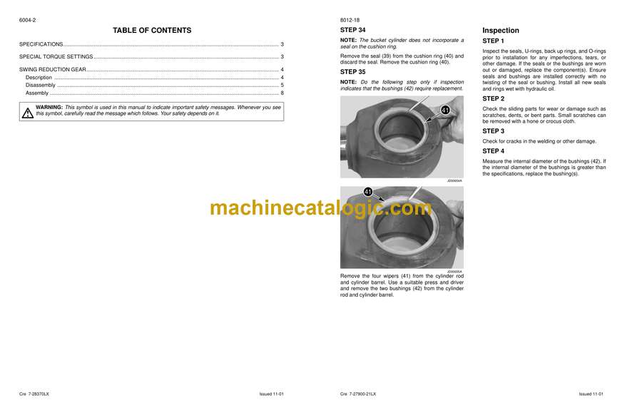
- Bucket cylinder description 8
- 8014.pdf
- 9003.pdf
- Removal 4
- Installation 4
- Shimming the bucket 6
- Removal 8
- Installation 8
- Removal 11
- Installation 12
- 4001.pdf
- General Location of Components (Outside the Cab) 6
- Relays and Main Fuses (Battery Compartment) 8
- General Location of Components (Inside the Cab) 9
- Fuse Box 11
- Instrument Panel 12
- H/S/L Mode Control 17
- Automatic Mode Control 18
- Acceleration Control 19
- Control of Engine Return to Idle (Automatic/Manual) 20
- Auxiliary Mode Control 21
- Automatic Engine Pre-heat 22
- Automatic Engine Warm-up 25
- 3) Diagram showing times 26
- Idle Control by Battery Voltage and Coolant Temperature 27
- Engine Emergency Stop 29
- Emergency Mode 31
- Lockout Functions 33
- Power Up 34
- Swing Brake 35
- Travel Speed 39
- Travel Alarm 42
- Supply Cut-Off Delayed 43
- Protection by Power Transistor 44
- Water Temperature Gauge 44
- Hydraulic Oil Temperature Gauge 46
- Fuel Level 47
- Engine Fuel Injection Pump Electronic Regulator 48
- Access to Control Screens 50
- Machine Condition 51
- Diagnostic Code 55
- Machine History 58
- Reset 61
- Message Display 64
- Prior Inspections 68
- Reading the Organization Charts 69
- Procedures 70
- Fuel 71
- Add Coolant Solution 72
- Low Engine Oil Pressure 73
- Overheating 74
- Battery Charge Circuit Defective 77
- Electrical System Troubleshooting 79
- Translation 83
- 5001.pdf
- Description 4
- Checking pin and bushing wear 12
- 5005.pdf
- Description 8
- Reconditioning 8
- Description 14
- Description 16
- Removal 16
- Notes
- 6003.pdf
- 6004.pdf
- 8003.pdf
- Removal and installation 4
- Removal and installation 9
- Removal and installation 11
- Notes
- 8005.pdf
- Description 3
- Description 9
- 8006.pdf
- Removal and installation 3
- 8008.pdf
- 8012.pdf
- Boom cylinder description 4
- Arm cylinder description 6
- Bucket cylinder description 8
- 8014.pdf
- 9003.pdf
- Removal 4
- Installation 4
- Shimming the bucket 6
- Removal 8
- Installation 8
- Removal 11
- Installation 12
Link Belt


