Format: PDF (Printable Document)
File Language: English
File Pages: 782
File Size: 102.16 MB (Speed Download Link)
Brand: Link Belt
Model: 225 Spin Ace Tier3 Excavator
Type of Document: Service Text Manual
$ 40
On a 225 Spin Ace working in tight urban digs or utility trenches, this service text manual is what I’d keep open when the machine starts acting up or comes in for scheduled work. It helps you trace systems, verify settings, and confirm dimensions so you’re not guessing. For example, if the excavator starts running hot or loses power under load, this is the book you use to track through the engine and cooling checks step by step and decide what to test next.
Applications & Use Cases
FAQ
Q: Can I use this manual on a tablet in the field?
A: Yes, it’s well suited for a tablet or laptop so you can zoom in on details and search text while standing at the machine.
Q: Is it worth printing sections of this manual?
A: Many techs print only the pages they need for a job, then mark notes or oily fingerprints on those instead of ruining a full book.
Safety Note
Always isolate hydraulic and electrical power and follow lockout procedures before inspecting or loosening any components.
Main body
Specifications
Overall
1. Main Data
2. Performance
3. Main Body Dimensions
4. Engine
5. Cooling System
6. Upper Side Work System
7. Operating Device
8. Swing Units
9. Travel Lower Body
10. Dozer Blade
Hydraulic Equipment
1. Hydraulic Device
2. Control Valve, Cylinder
Capacities, Filters
1. Coolant and Oil Capacities
2. Hydraulic Oil Filters
3. Fuel Filter
Overall View
Overall View (225)
1. Standard Arm (3.00 m)
2. Short Arm (2.40 m)
3. S-Short Arm (1.93 m)
Overall View (225 Blade)
1. Standard Arm (3.00 m)
2. Short Arm (2.40 m)
3. S-Short Arm (1.93 m)
Work Range Diagram
Work Range Diagram (225)
1. Standard Arm (3.00 m)
2. Short Arm (2.40 m)
3. S-Short Arm (1.93 m)
Work Range Diagram (225 Blade)
1. Standard Arm (3.00 m)
2. Short Arm (2.40 m)
3. S-Short Arm (1.93 m)
Specifications
Optional Components
List of Optional Components
Major Equipment Specifications
Equipment Configuration
Overall
Operator’s Cab
Main Equipment Table
Lower Mechanism
Assembly Diagrams
Assembly Diagrams(WITH DOZER BLADE)
Lower Component
1. Travel Unit
2. Take-up Roller
3. Upper-roller
4. Lower-roller
5. Recoil Spring
6. Shoes
Upper Component
1. Swing Unit
Engine-related
1. Engine
2. Muffler
3. Air Cleaner (double element)
4. Radiator
Hydraulic Device
1. Hydraulic pump
Control-related
1. Control Valve
2. Solenoid Valve (4 stack)
3. Remote Control Valve (left / right, travel operations)
4. Remote Control Valve Characteristic Diagram
5. Cushion Valve (heat circuit, with shuttle valve)
6. Selector Valve (option)
7. Center Joint
Backhoe Attachment
1. Cylinder
2. Attachments
Fuel Tank
Sump Tank
Rotating Joint
Rotating Joint (Blade)
2
Table of Contents
3 RST-15-00-001LX
Hydraulic Section
Hydraulic Pump
Equipment Configuration
Hydraulic Pump Structure
Operational Description of Hydraulic Pump
Operational Description of Control Section
Control Valve
Operation
1. Operation with all Spools in Neutral Position
Single Operation
1. Travel Spool Switching
2. Backup Spool Switching
3. Swing Spool Switching
4. Bucket Spool Switching
5. Boom Spool Switching
6. Arm Spool Switching
7. Parallel Restriction for Arm
8. Relief Valve
Combined Operation
1. Travel Combined Operation
Anti-drift Valve
1. Neutral State (Port A5 – holding state)
2. Shut-off of Continuity Between Port A5 and Spring Chamber
3. Main Poppet Activated
Relief Valve
1. Operation of the Main Relief Valve
2. Operation of the Overload Relief Valve
3. Draw-in-oil Feature of the Overload Relief Valve
4. Function of Low-pressure Relief Valve
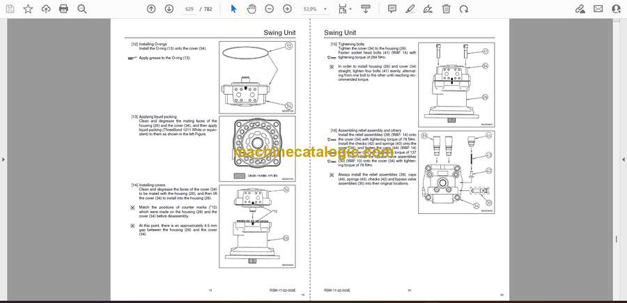
Swing Unit
Component Configuration
Hydraulic Motor Structure
Operational Description of Hydraulic Motor
Operational Description of Mechanical Brake
Operational Description of Make-up Valve
Operational Description of Relief Valve (Internal structural drawing of relief valve)
Operational Description of Bypass Valve (Internal structural drawing of bypass valve)
Swing Reduction Gear
Main Equipment Structure and Operation Explanation
Motor
1. Travel Motor
Hydraulic Circuit Section
Port Locations
Hydraulic Pump
Control Valve
Pilot Hose Connection Diagrams
Pilot P & T Lines
Pilot Control Lines
Functional Explanation
Function Table
Travel Circuits
High Speed Travel Circuit
Low Speed Travel Circuit
Straight Travel Circuit
Swing Circuits
Swing Parking Circuit (Independent Operation of Swing)
Swing Override Variable Throttle Circuit
Arm Circuits
Arm Out Circuit
Arm In Load Holding
Arm In Circuit
Boom Circuits
Boom Up Circuit (single)
Boom Up Circuit (combined)
Boom Down Load Holding
Boom Down Circuit
Backup Circuits
Breaker Circuit
Combined Circuit (high speed confluence circuit)
4
Table of Contents
5 RST-15-00-001LX
Electric Circuits Section
Explanation of New Functions
Work Mode Select Switch
Pump Electromagnetization Proportional Valve
Explanation of Electrical Functions
Engine Control
1. Throttle Control
2. One-touch Idle Control
3. Auto Warm-up
Engine Start / Stop Control
1. Engine Start
2. Neutral Start
3. Glow
4. Idling Start
5. Engine Stop
6. Power-cut Delay
7. Engine Emergency Stop
8. Engine Start / Stop Judgment
Pump Control
1. Work Mode Control
2. Constant Horsepower Control
3. Travel Horsepower Boost
4. Engine Stall Prevention (during low idle)
5. High Altitude Correction
Swing
1. Swing Brake
Travel
1. Travel Speed Switchover
2. Travel Alarm
Valve Control
1. Lever Lock
2. Solenoid Sticking Prevention
3. Pressure Boost Control
Monitor Control
1. Fuel Gauge / Refueling Warning
2. Coolant Temperature Gauge and Oil Temperature Gauge / Overheat Warning
3. Battery Charge Warning
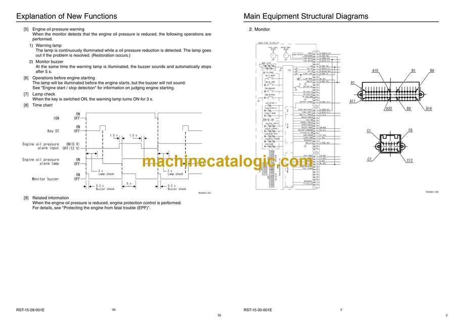
4. Engine Oil Pressure Warning
5. Hydraulic Oil Filter Clog Warning
6. Engine Abnormality Warning
7. Overload Warning
8. Hour Meter
Accessories
1. Horn
2. Working Light
3. Backlight
4. Wiper and Washer
5. Room Lamp
6. Radio
7. Cigar Lighter (overseas only)
8. 12 V Power Supply (overseas only)
9. Beacon (for Europe / Turkey)
Other
1. Key ON Alarm
2. Battery Save Function
3. Charging Circuit / Backup / Accessories
4. Pilot Pressure Detection
Options
1. Option Line Control
2. Model Setting
Service Support
1. Finding Diagnostic Trouble Codes
2. Rewriting Programs
3. Rewriting Programs
6
Table of Contents
7 RST-15-00-001LX
Service Support
Screen Operations
1. Screen Shift
Screen Display List
1. CHK (status display) Screen List
2. DIAG (trouble diagnosis) Screen
3. HR (usage log) Screen List
4. CFG (setting change) Screen
5. CAL (troubleshooting support) Screen
6. Check the Monitor Switch (self-diagnosis function)
7. Model Setting
8. Engine Screen Information
Screen Display Details
1. Message Display List
Trouble Display
1. Diagnostic Trouble Code Display
2. Main Unit Diagnostic Trouble Code List
3. Diagnostic Trouble Code (monitor display)
4. Sensor Trouble Operation Table
5. EPF (Engine Protection Feature)
Main Equipment Structural Diagrams
Connection Connector Pin Layout
1. Computer A
2. Monitor
Main Equipment Structural Diagrams
Overall View
1. Sequence Circuit Diagram
Block Diagram
1. Computer A
2. ECM
3. Monitor Display
4. Air Conditioner
5. Lever Lock
6. Horn
7. Others
8. Electrical Symbol ListHarness Diagrams
Wire Harness
1. Main Frame Harness
2. Cab Main Harness
3. Cab Sub Harness
4. In Cab
5. Engine Harness
Electric Wiring Diagrams
Overall View
1. Main Unit Left Side Layout Diagram (radiator chamber)
2. Engine Section Layout Diagram
3. Main Unit Right Side Layout Diagram (pump chamber)
4. Main Unit Right Side Layout Diagram (control valve chamber)
5. Cab Layout Diagram
6. Layout Around Operator Seat
Stand Alone Parts Diagram
Harness Diagrams
Electrical Components and Wiring for Upper Frame (1/4)
Electrical Components and Wiring for Upper Frame (2/4)
Electrical Components and Wiring for Upper Frame (3/4)
Electrical Components and Wiring for Upper Frame (4/4)
Electrical Components and Wiring for Cab
8
Table of Contents
9 RST-15-00-001LX
Maintenance Section
Instructions for Measuring and Adjusting Pressure
Measuring Pressure
1. Basic Conditions
2. Set Values
3. Pressure Measuring ports
4. Preparations for Measuring Pressure
5. Measuring pressure
Adjusting Pressure
1. Pressure Adjusting Points
2. Instructions for adjusting pressure
Compatibility
Main Parts Common Features and Compatibility List
Attachments Dimensions


