Format: PDF (Printable Document)
File Language: English
File Pages: 1154
File Size: 65.18 MB (Speed Download Link)
Brand: Link Belt
Model: 350X2 Excavator
Type of Document: Shop Manual
$ 40
On a 350X2, you’re usually digging deep trenches, loading trucks, or handling rock in rough sites where downtime hurts. This shop manual is what I’d keep open when I’m tearing into major components or chasing a stubborn hydraulic or cooling issue. It walks you through how to strip, inspect, and reassemble the big systems in a way that keeps you from missing hidden wear or mixing up parts. If, for example, the machine starts running hot under load, this is the document I’d use to trace the cooling circuit, verify flow paths, and rebuild components with confidence that it’ll hold up back in the dirt.
Applications & Use Cases
FAQ
Q: Can I use this manual on a tablet in the field?
A: Yes, it’s practical on a tablet; just zoom in on diagrams and keep the screen clean so details stay readable.
Q: Is it worth printing sections of this manual?
A: For bigger jobs, printing the relevant pages and keeping them at the bench helps you follow each step without scrolling.
Safety Note
Always lock out the machine, relieve hydraulic pressure, and support components securely before following any procedure from this manual.
Main Body Section
Specifications
Overall
1. Main Data
2. Performance
3. Main Unit Dimensions
4. Engine
5. Cooling System
6. Upper Side Work System
7. Operating Device
8. Swing Units
9. Travel Lower Body
Hydraulic Equipment
1. Hydraulic Device
2. Control Valve, Cylinder
Capacities, Filters
1. Coolant and Oil Capacities
2. Hydraulic Oil Filters
3. Fuel Filter
Lifting Capacity
Precautions for lifting loads with the hydraulic excavator
Lifting Capacities (Standard Arm)
Lifting Capacities (Short Arm)
Lifting Capacities (Long Arm)
Overall View
Overall View (350X2)
1. Standard Arm (3.25 m)
2. Short Arm (2.63 m)
3. Long Arm (4.04 m)
Work Range Diagram
Work Range Diagram (350X2)
1. Standard Arm (3.25 m)
2. Short Arm (2.63 m)
3. Long Arm (4.04 m)
Summary Section
Main Equipment Table
Lower Component
1. Travel Unit
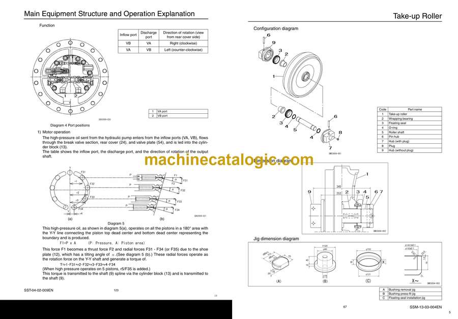
2. Take-up Roller
3. Upper Roller
4. Lower Roller
5. Recoil Spring
6. Shoe
Upper Component
1. Swing Unit
Engine-related
1. Engine
2. Muffler
3. Air Cleaner (double element)
4. Radiator
Hydraulic Device
1. Hydraulic Pump
2. Pump P-Q Diagram
Control-related
1. Control Valve
2. Solenoid Valve (5 stack)
3. Remote Control Valve (left/right, travel operations)
4. Remote Control Valve Characteristic Diagram
5. Cushion Valve (heat circuit, with shuttle valve)
6. Selector Valve (option)
7. Center Joint
Backhoe Attachment
1. Cylinder
2. Attachments
Equipment Layout Diagram
Main Equipment Layout
Consumable Part Layout
Standard Machine Option List
List of Optional Components
2
Contents
SST-00-00-010LX
Hydraulics Section
Hydraulic Equipment Layout
Overall View
Pump Chamber Hydraulic Equipment Layout
Swing Body Center Section Hydraulic Equipment Layout
Housing Left Side Hydraulic Equipment Layout
Layout of Hydraulic Equipment in Cab
Port Diagram
Pump
1. Hydraulic Pump (standard model)
Valves
1. Control Valve
2. 5 Stack Solenoid Valve
3. 2 Stack Solenoid Valve
4. Remote Control Valves (upper, travel)
5. Cushion Valve
6. 4-way Multi-valve
7. 2-way Multi-valve
8. Direction Valve/Shut-off Valve
9. HBCV (Option)
Manifolds
1. Manifold Under Cab
2. Manifold (accumulator section)
3. Manifold (hydraulic oil tank section)
Motors
1. Swing Motor
2. Travel Motor
3. Center Joint
Pilot Hose Connection Diagram
Pilot P and T Lines
Pilot Control Line
Pilot Control Line (2-way selector valve)
Pilot Control Line (4-way selector valve)
Function List
Function Table
Explanation of New Functions
1. Swing Relief Cut-off Control
2. Swing Speed Limit Control
3. Negative Control Power Save Control
4. Option Line Flow Adjustment Control
5. Multi Purpose Circuit (breaker ⇔ crusher) One-touch Switching Control
6. Bucket-close Regenerative Circuit
Explanation of Hydraulic Circuit and Operations (standard model)
Travel Circuit
Travel low-speed circuit
Travel high-speed circuit
Straight travel circuit
Swing Circuit
Swing speed limit control circuit
Swing relief cut-off control circuit
Swing priority circuit
Swing brake circuit
Swing parking circuit (lever in neutral)
Swing parking circuit (brake release)
Swing parking circuit (machine stop)
Boom Circuit
Boom-up circuit (independent operation)
Boom-up circuit (compound boom-up + arm-in)
Boom-down regenerative circuit
Boom-down tilting prevention circuit
Boom-down load holding valve circuit
Arm Circuit
Arm-out circuit
Arm-in forced regenerative circuit
Arm-in load holding valve circuit
Bucket Circuit
Bucket-open circuit
Bucket-close regenerative circuit
Negative Control Circuit
Negative control circuit (power save solenoid OFF)
Negative control power save circuit (power save solenoid ON)
Negative control circuit (bucket close, power save solenoid OFF)
Other Circuits
Cushion circuit (arm-out operation)
Cushion circuit (arm-out operation stopped)
Cushion circuit (arm-out → arm-in operation)
Heat circuit (lever in neutral)
Auto pressure boost circuit (bucket close)
4
Contents
SST-00-00-010LX
Explanation of Hydraulic Circuit and Operations (option)
Option Circuits
Breaker circuit (independent operation)
Double-acting circuit (hydraulic fork)
Multi-purpose circuit (breaker Q control)
Multi-purpose circuit (2 pumps flow crusher)
2nd option circuit (hydraulic rotation fork)
Main Equipment Structure and Operation Explanation
Pump
1. Hydraulic Pump
2. Regulator
3. Gear Pump
Motor
1. Travel Motor
2. Swing Motor
Valve
1. Control Valve
2. 5 Stack Solenoid Valve Operation Explanation
3. Upper Pilot Valve (remote control valve)
4. Travel Pilot Valve (remote control valve)
5. Cushion Valve
6. Selector Valve (4-way)
7. Direction Valve (3-direction)


