$ 0
0
$ 0
0

Link Belt 75 Spin Ace Interim Tier 4 Excavator Shop Manual

Format: PDF (Printable Document)

File Language: English

File Pages: 640

File Size: 78.46 MB (Speed Download Link)
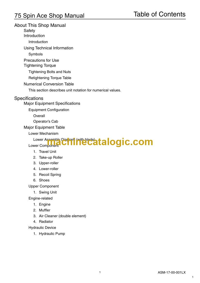
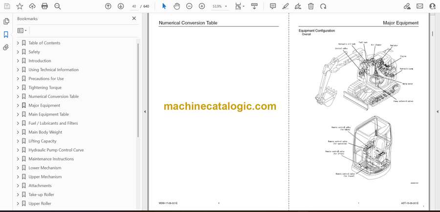
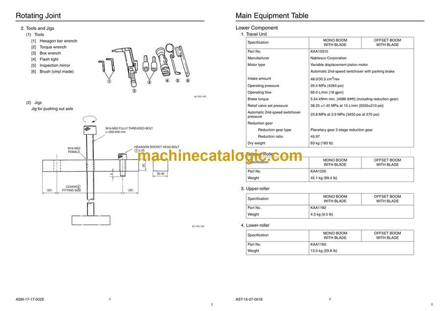
Brand: Link Belt

Model: 75 Spin Ace Interim Tier 4 Excavator

Type of Document: Shop Manual

Category:

$ 40

Share:

Link Belt 75 Spin Ace Interim Tier 4 Excavator Shop Manual

Link Belt 75 Spin Ace Interim Tier 4 Excavator Shop Manual

📘 Show Index

Link Belt 75 Spin Ace Interim Tier 4 Excavator Index:

  • Table of Contents
    • Table of Contents
      • Table of Contents
      • About This Shop Manual
  • Safety
    • Safety
      • Safety
  • Introduction
    • Introduction
      • Introduction
      • Introduction
  • Using Technical Information
    • Using Technical Information
      • Using Technical Information
      • Symbols
  • Precautions for Use
    • Precautions for Use
      • Precautions for Use
      • Maintenance and inspection methods
  • Tightening Torque
    • Tightening Torque
      • Tightening Torque
      • Tightening Bolts and Nuts
  • Numerical Conversion Table
    • Numerical Conversion Table
      • Numerical Conversion Table
      • This section describes unit notation for numerical values.
  • Major Equipment
    • Major Equipment
      • Major Equipment
      • Equipment Configuration
  • Main Equipment Table
    • Main Equipment Table
      • Main Equipment Table
      • Lower Mechanism
  • Fuel / Lubricants and Filters
    • Fuel / Lubricants and Filters
      • Fuel / Lubricants and Filters
      • Fuel / Lubricants for Different Ambient Temperature Settings
  • Main Body Weight
    • Main Body Weight
      • Main Body Weight
      • Major Component Weight (Standard Specifications)
  • Lifting Capacity
    • Lifting Capacity
      • Lifting Capacity
      • Precautions for lifting loads with the hydraulic excavator
  • Hydraulic Pump Control Curve
    • Hydraulic Pump Control Curve
      • Hydraulic Pump Control Curve
      • P-Q Line Diagram of Hydraulic Pump
  • Maintenance Instructions
    • Maintenance Instructions
      • Maintenance Instructions
      • Process Block Diagram for Lower Equipment
  • Lower Mechanism
    • Lower Mechanism
      • Lower Mechanism
      • Track Shoe
  • Upper Mechanism
    • Upper Mechanism
      • Upper Mechanism
      • Swing Unit
  • Attachments
    • Attachments
      • Attachments
      • Bucket Cylinder Removal and Installation
  • Take-up Roller
    • Take-up Roller
      • Take-up Roller
      • Disassembling and Assembling Instructions
  • Upper Roller
    • Upper Roller
      • Upper Roller
      • Disassembling and Assembling Instructions
  • Lower Roller
    • Lower Roller
      • Lower Roller
      • Disassembling and Assembling Instructions
  • Grease Cylinder
    • Grease Cylinder
      • Grease Cylinder
      • Disassembling and Assembling Instructions
  • Rotating Joint
    • Rotating Joint
      • Rotating Joint
      • Disassembling and Assembling Instructions
  • Air Conditioner
    • Air Conditioner
      • Air Conditioner
      • Disassembling the case
  • Maintenance Standards
    • Maintenance Standards
      • Maintenance Standards
      • Check Sheet
  • Hydraulic Pump
    • Hydraulic Pump
      • Hydraulic Pump
      • Disassembling and Assembling Instructions
  • Travel Unit
    • Travel Unit
      • Travel Unit
      • Service Outline
  • Swing Unit
    • Swing Unit
      • Swing Unit
      • Maintenance Instructions
  • Control Valve
    • Control Valve
      • Control Valve
      • Maintenance Instructions
  • Cylinder
    • Cylinder
      • Cylinder
      • Structural Drawings
  • Remote Control Valve
    • Remote Control Valve
      • Remote Control Valve
      • Safety Information
  • Solenoid Valve (3 stack)
    • Solenoid Valve (3 stack)
      • Solenoid Valve (3 stack)
      • Assembly Drawing
  • Cushion Valve
    • Cushion Valve
      • Cushion Valve
      • Structure

Link Belt

Latest Product

0
    0
    Your Cart
    Your cart is emptyReturn to Shop