Format: PDF (Printable Document)
File Language: English
File Pages: 778
File Size: 56.82 MB (Speed Download Link)
Brand: Link Belt
Model: 800LX Excavator
Type of Document: Service Text Manual
$ 40
The Link Belt 800LX is a large excavator that usually lives in quarries, heavy civil jobs, and bulk earthmoving where it’s working hard all day in dust, mud, and rock. This Service Text Manual is what I’d keep on hand when I’m actually wrenching on the machine—using it to trace systems, confirm procedures, and verify I’m putting things back together the way Link Belt intended. For example, if the boom won’t hold load and slowly creeps down, I’d use this manual to walk through the hydraulic checks, isolate whether it’s a control issue or internal leakage, and then confirm the correct adjustment or repair steps.
Applications & Use Cases
FAQ
Q: Can I use this manual on a tablet in the field?
A: Yes, it’s practical to keep it on a tablet so you can zoom in on text and keep your hands free while working.
Q: Is it worth printing sections of this manual?
A: Many techs print only the pages they need for a job and keep them in a binder so they don’t ruin their device in bad weather.
Safety Note
Always lock out, tag out, and safely support all components before following any procedure from this manual.
Main Body Section
Page
Specifications
Specifications ………………………………………………………800-1-01-00-58 1/7 1
Complete Machine Dimensions………………………………800-1-01-01-56
Standard Arm (3.66 m) …………………………………………………………… 1/4 8
Long Arm (4.44 m) …………………………………………………………………. 2/4 9
Super Long Arm (5.62 m) ……………………………………………………….. 3/4 10
Mass Digging Arm (2.98 m) …………………………………………………….. 4/4 11
Work Range…………………………………………………………800-1-01-02-56
Standard Arm (3.66 m) …………………………………………………………… 1/4 12
Long Arm (4.44 m) …………………………………………………………………. 2/4 13
Super Long Arm (5.62 m) ……………………………………………………….. 3/4 14
Mass Digging Arm (2.98 m) …………………………………………………….. 4/4 15
Optional Components……………………………………………800-1-01-03-28
List of Optional Components……………………………………………………. 1/1 16
Emission Control Regulation of 3rd-Stage…… 700-1-01-06-03
Execution Time Emission Control Regulation ………………………………… 1/12 17
Standard Amount of Exhaust Gas ………………………………………………… 2/12 18
Measures to be Taken for The Emission Control Regulation
………………………………………………………………………………………….. 3/12 19
Engine fuel and maintenance of fuel filters…………………………………….. 4/12 20
Engine system Diagram ……………………………………………………………… 7/12 23
Construction of Engine (ISUZU 6WGIT)………………………………………… 8/12 24
Common Rail Injection System ……………………………………………………. 9/12 25
Suction and Exhaust System……………………………………………………….. 11/12 27
Major Equiment Specifications
Equipment …………………………………………………………..700-2-01-00-15
Overall………………………………………………………………………………….. 1/2 29
Operator’s Cab………………………………………………………………………. 2/2 30
Lower Mechanism ………………………………………………..800-2-01-01-48
Assembly Drawing …………………………………………………………………. 1/3 31
Travel Unit…………………………………………………………………………….. 2/3 32
Take-up Roller ………………………………………………………………………. 2/3 32
Upper-Roller………………………………………………………………………….. 2/3 32
Lower Roller………………………………………………………………………….. 2/3 32
Recoil Spring…………………………………………………………………………. 3/3 33
Shoes…………………………………………………………………………………… 3/3 33
Upper Mechanism ………………………………………………..800-2-01-02-45
Swing Unit…………………………………………………………………………….. 1/1 34
Engine and Related Areas……………………………………..800-2-01-03-47
Engine………………………………………………………………………………….. 1/3 35
Muffler ………………………………………………………………………………….. 2/3 36
Air Cleaner (With pre cleaner) …………………………………………………. 2/3 36
Radiator ……………………………………………………………………………….. 2/3 36
Fuel Tank ……………………………………………………………………………… 3/3 37
Hydraulic System………………………………………………….800-2-01-04-48
Hydraulic Pump……………………………………………………………………… 1/3 38
Sump Tank……………………………………………………………………………. 2/3 39
Rotating Joint ………………………………………………………………………… 3/3 40
Solenoid Valve ………………………………………………………………………. 3/3 40
Controls ………………………………………………………………800-2-01-05-49
Control Valve ………………………………………………………………………… 1/2 41
Remote Control Valve (Left / Right, Travel operations) ……………….. 2/2 42
Backhoe Attachments……………………………………………800-2-01-06-50
Cylinder………………………………………………………………………………… 1/2 43
Attachments ………………………………………………………………………….. 2/2 44
Page No. 2
SH800
800-1-00-00-31
Table of Contents / 9
First Edition :02/2006
Hydraulic Section
Page
Hydraulic Pump………………………………………………….700-1-02-01-18
Operation Principle …………………………………………………………………….. 1/2 45
Internal Structure Drawing…………………………………………………………… 2/2 46
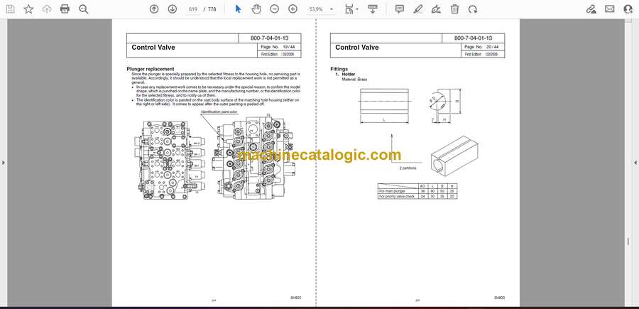
Contorol Valve ……………………………………………………700-1-02-02-15
Operation Explanation of Each Part ……………………………………………… 1/16 47
1.Main Relief Valve ………………………………………………………………… 2/16 48
2.Overload Relief Valve ………………………………………………………….. 4/16 50
3.Foot Relief Valve…………………………………………………………………. 7/16 53
4.Load Holding Valve……………………………………………………………… 8/16 54
5.Arm Regenerative ……………………………………………………………….. 11/16 57
6.Priority Valve………………………………………………………………………. 14/16 60
7.Boom Regenerative …………………………………………………………….. 16/16 62
Swing Unit …………………………………………………………..700-1-02-03-12
Operation Principle …………………………………………………………………….. 1/6 63
1.Hydraulic Motor…………………………………………………………………… 1/6 63
2.Anti-cavitation Check Valve Section ………………………………………. 1/6 63
3.Relief Valve………………………………………………………………………… 2/6 64
4.Reversal Prevention Valve……………………………………………………. 4/6 66
5.Brake Section……………………………………………………………………… 5/6 67
Internal Structure Drawing…………………………………………………………… 6/6 68
Travel Unit …………………………………………………………..700-1-02-04-15
Operation Principle …………………………………………………………………….. 1/10 69
1.Hydraulic Motor…………………………………………………………………… 1/10 69
2.Parking Brake …………………………………………………………………….. 2/10 70
3.2-Speed Switch Mechanism Oparation Principle……………………… 3/10 71
4.Relief Valve………………………………………………………………………… 8/10 76
5.Double Counterbalance Value ………………………………………………. 9/10 77
Fan Motor for Hydraulic Drive………………………….700-1-02-05-02
Outside Drawing ………………………………………………………………………… 1/7 79
Internal Structure Drawing…………………………………………………………… 2/7 80
Operation Principle …………………………………………………………………….. 3/7 81
1.Hydraulic Motor…………………………………………………………………… 3/7 81
2.Suction Safety Valve……………………………………………………………. 4/7 82
3.Variable Flow Control Valve………………………………………………….. 6/7 84
4.Operation of Forward / Reverse Changeover Valve …………………. 7/7 85
Page No. 4
SH800
800-1-00-00-31
Table of Contents / 9
First Edition :02/2006
Hydraulic Circuits Section
Page
Port Locations…………………………………………………….700-1-03-00-23
Hydraulic Pump …………………………………………………………………………. 1/2 86
Control Valve …………………………………………………………………………….. 2/2 87
Pilot Hose Connection Diagrams ……………………800-1-03-01-28
Pilot P&T Lines ………………………………………………………………………….. 1/4 88
Pilot Control Lines ……………………………………………………………………… 3/4 90
Functional Explanation……………………………………..800-1-03-02-25
Functional Table ………………………………………………………………………… 1/2 92
Travel Circuits…………………………………………………….800-1-03-03-22
High Speed Travel Circuit……………………………………………………………. 1/6 94
Low Speed Travel Circuit ……………………………………………………………. 3/6 96
Straight Travel Circuit …………………………………………………………………. 5/6 98
Swing Circuits…………………………………………………….800-1-03-04-23
Swing Parking Circuit (Lever in Neutral / Swing Locked) …………………. 1/6 100
Swing Parking Circuit (Brake Released) ……………………………………….. 3/6 102
Swing Push Digging …………………………………………………………………… 5/6 104
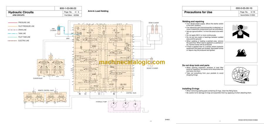
Arm Circuits………………………………………………………..800-1-03-06-22
Arm-Out Circuit………………………………………………………………………….. 1/6 106
Arm-In Load Holding…………………………………………………………………… 3/6 108
Arm-In Circuit…………………………………………………………………………….. 5/6 110
Boom Circuits …………………………………………………….800-1-03-07-22
Boom-Up Circuit (Single)…………………………………………………………….. 1/8 112
Boom-Up Circuit (Combined) ………………………………………………………. 3/8 114
Boom-Down Load Holding…………………………………………………………… 5/8 116
Boom-Down Circuit…………………………………………………………………….. 7/8 118
Backup Circuits………………………………………………….800-1-03-09-21
Combined Circuit (Breaker Circuit) ……………………………………………….. 1/4 120
Combined Circuit (High Speed Confluence Circuit) ………………………… 3/4 122
Other Circuits……………………………………………………..800-1-03-13-04
High Dump………………………………………………………………………………… 1/2 124
Maintenance Section
Page
New Machine Performance
Performance Evaluation Check Sheet……………………..000-3-02-00-15 1/2 231
Reference Values …………………………………………………800-3-02-01-25 1/1 233
Instructions For Measuring And Adjusting Pressure
…………………………………………………………………….800-1-05-00-28
Measuring Pressure …………………………………………………………………… 1/14 234
1.Basic Conditions …………………………………………………………………. 1/14 234
2.Set Values………………………………………………………………………….. 1/14 234
3.Pressure Measuring port………………………………………………………. 2/14 235
4.Preparation for Measuring Pressure ………………………………………. 4/14 237
5.Measuring Pressure…………………………………………………………….. 6/14 239
6.Measuring Other Pressures ………………………………………………….. 8/14 241
Adjusting Pressure …………………………………………………………………….. 9/14 242
1.Pressure Adjusting Points…………………………………………………….. 9/14 242
2.Instructions for Adjusting Pressure ………………………………………… 11/14 244
Maintenance Of The Circumference Of Engine
…………………………………………………………………….700-1-05-07-03
1.Circumference Filter Arrangement of Engine ………………………………. 1/3 248
2.Fuel Element System Diagram………………………………………………….. 2/3 249
Main Body Weight ……………………………………………..800-3-01-00-49
1.Major Component Weight…………………………………………………………. 1/2 251
2.Individual Part Weight………………………………………………………………. 2/2 252
3.Shoe Weight …………………………………………………………………………… 2/2 252
4.Arm Weight…………………………………………………………………………….. 2/2 252
Attachments Dimensions …………………………………800-1-05-04-22 1/1 253
Compatibility ………………………………………………………800-1-05-05-26 1/1 254
Plastic Shim………………………………………………………..000-1-05-08-02 1/1 255
Procedures For Changing Operation Type…… 000-8-02-01-07
1.ISO Type ……………………………………………………………………………….. 1/4 256
2.Old SumitomoType………………………………………………………………….. 2/4 257
3.Old Mitsubishi Type …………………………………………………………………. 3/4 258
4.Old Kobelco Type ……………………………………………………………………. 4/4 259
Page No. 8
SH800
800-1-00-00-31
Table of Contents / 9
First Edition :02/2006
Assembly, Disasembly Section
Page
Summary of Assembling ………………………………….800-0-06-00-05
Total Work Process ……………………………………………………………………. 1/36 260
Major Machines ・ Tools ・ Equipment Table…………………………………… 2/36 261
Matters to be Attended ……………………………………………………………….. 5/36 264
Prior Preparation ……………………………………………………………………….. 5/36 264
Prior Preparation Procedure………………………………………………………… 7/36 266
Unloading Work …………………………………………………………………………. 8/36 267
Connection of Lower Sideframes to Upper Swing Body…………………… 14/36 273
Mounting Travel Motor Lines ……………………………………………………….. 20/36 279
Mounting Counterweight……………………………………………………………… 22/36 281
Mounting Attachments………………………………………………………………… 24/36 283
Checking Work ………………………………………………………………………….. 34/36 293
Confirmation of Movement After Assembling Work…………………………. 35/36 294
Summary of Disassembling……………………………..800-1-06-01-05 1/5 296
Attached Data……………………………………………………..800-1-06-02-06 1/8 301
Appendix
Unit Conversion Table …………………………………………..300-1-08-01-02 1/1 309
New Hydraulic Oil …………………………………………………300-1-08-02-02 1/1 310


