Format: PDF (Printable Document)
File Language: English
Brand: Link Belt Crane
Model: 248 Hylab 5
Type of Document: Service Manual
Engine Model:
$ 55
SECTION 0 General
How To Use This Manual, General Service Instructions, And Safety Procedures . . . . . . . SM00−000−001.00
Equipment Layout . . . . . . . . . . . . . . . . . . . . . . . . . . . . . . . . . . . . . . . . . . . . . . . . . . . . . . . . . . . . . . ES00−03−0075.0R0S
SECTION 1 Upper Mechanism
Power Transmission System . . . . . . . . . . . . . . . . . . . . . . . . . . . . . . . . . . . . . . . . . . . . . . . . . . . . . ES01−01−0084.0R0S
Front And Rear Drum Shaft Structure And Outline . . . . . . . . . . . . . . . . . . . . . . . . . . . . . . . . . . ES01−10−0061.0R0S
Front And Rear Drum Shaft Maintenance Chart . . . . . . . . . . . . . . . . . . . . . . . . . . . . . . . . . . . . ES01−10−2061.0R0S
Front And Rear Drum Shaft Disassembly And Reassembly . . . . . . . . . . . . . . . . . . . . . . . . . . ES01−10−6061.0R0S
Boom Hoist Drum Shaft Structure And Outline . . . . . . . . . . . . . . . . . . . . . . . . . . . . . . . . . . . . . ES01−15−0061.0R0S
Boom Hoist Drum Shaft Maintenance Chart . . . . . . . . . . . . . . . . . . . . . . . . . . . . . . . . . . . . . . . ES01−15−2052.0R0S
Boom Hoist Drum Shaft Disassembly And Reassembly . . . . . . . . . . . . . . . . . . . . . . . . . . . . . ES01−15−6065.0R0S
Clutch Structure And Outline (1−Cylinder Type) . . . . . . . . . . . . . . . . . . . . . . . . . . . . . . . . . . . . ES01−17−0061.0R0S
Clutch Maintenance Chart (1−Cylinder Type) . . . . . . . . . . . . . . . . . . . . . . . . . . . . . . . . . . . . . . ES01−17−2079.0R0S
Clutch Troubleshooting (1−Cylinder Type) . . . . . . . . . . . . . . . . . . . . . . . . . . . . . . . . . . . . . . . . ES01−17−4023.0R0S
Clutch Disassembly And Reassembly (1−Cylinder Type) . . . . . . . . . . . . . . . . . . . . . . . . . . . . ES01−17−6061.0R0S
Swing Mechanism Maintenance Chart . . . . . . . . . . . . . . . . . . . . . . . . . . . . . . . . . . . . . . . . . . . . ES01−29−2053.0R0S
Turntable Bearing Maintenance Chart . . . . . . . . . . . . . . . . . . . . . . . . . . . . . . . . . . . . . . . . . . . . . ES01−30−2030.5R0S
Turntable Bearing Inspection And Adjustment . . . . . . . . . . . . . . . . . . . . . . . . . . . . . . . . . . . . . ES01−30−5053.0R0S
Drum Indicator Troubleshooting . . . . . . . . . . . . . . . . . . . . . . . . . . . . . . . . . . . . . . . . . . . . . . . . . . ES01−50−4001.1R0S
SECTION 3 Control System
Front And Rear Drum Brake Control Maintenance Chart . . . . . . . . . . . . . . . . . . . . . . . . . . . . ES03−05−2075.0R0S
Front And Rear Drum Brakes Control Inspection And Adjustment . . . . . . . . . . . . . . . . . . . . ES03−05−5069.0R0S
Front And Rear Drum Brakes Control Disassembly And Reassembly . . . . . . . . . . . . . . . . . ES03−05−6076.0R0S
Front, Rear And Boom Hoist Drum Lock Pawl Control Maintenance Chart . . . . . . . . . . . . . ES03−10−2070.0R0S
SECTION 4 Hydraulic System
Hydraulic Circuit Outline . . . . . . . . . . . . . . . . . . . . . . . . . . . . . . . . . . . . . . . . . . . . . . . . . . . . . . . . ES04−01−0088.0R0S
Hydraulic Circuit Pressure Adjustment . . . . . . . . . . . . . . . . . . . . . . . . . . . . . . . . . . . . . . . . . . . . ES04−01−5084.0R0S
SECTION 5 Hydraulic Unit
Hydraulic Equipment Layout . . . . . . . . . . . . . . . . . . . . . . . . . . . . . . . . . . . . . . . . . . . . . . . . . . . . . ES05−01−0020.0R0S
Variable Pump Structure And Outline . . . . . . . . . . . . . . . . . . . . . . . . . . . . . . . . . . . . . . . . . . . . . ES05−02−0069.0R0S
Variable Delivery Pump Maintenance Chart . . . . . . . . . . . . . . . . . . . . . . . . . . . . . . . . . . . . . . . . ES05−02−2052.0R0S
Variable Delivery Pump Troubleshooting . . . . . . . . . . . . . . . . . . . . . . . . . . . . . . . . . . . . . . . . . . ES05−02−4009.0R0G
Variable Delivery Pump Disassembly And Reassembly . . . . . . . . . . . . . . . . . . . . . . . . . . . . . . ES05−02−6042.0R0S
Gear Pump Disassembly And Reassembly (2−Series Type) . . . . . . . . . . . . . . . . . . . . . . . . . ES05−03−6054.0R0S
Accumulator Structure . . . . . . . . . . . . . . . . . . . . . . . . . . . . . . . . . . . . . . . . . . . . . . . . . . . . . . . . . . ES05−05−0035.1R0S
Accumulator Inspection . . . . . . . . . . . . . . . . . . . . . . . . . . . . . . . . . . . . . . . . . . . . . . . . . . . . . . . . . ES05−05−5032.1R0S
Accumulator Disassembly And Reassembly . . . . . . . . . . . . . . . . . . . . . . . . . . . . . . . . . . . . . . . ES05−05−6046.1R0S
Front And Rear Winch Motor
Axial Piston Motor Structure And Outline . . . . . . . . . . . . . . . . . . . . . . . . . . . . . . . . . . . . . . . . . . ES05−09−0044.2R0S
Motor Maintenance Chart . . . . . . . . . . . . . . . . . . . . . . . . . . . . . . . . . . . . . . . . . . . . . . . . . . . . . . . ES05−09−2025.0R0S
Motor Troubleshooting . . . . . . . . . . . . . . . . . . . . . . . . . . . . . . . . . . . . . . . . . . . . . . . . . . . . . . . . . . ES05−09−4011.0R0S
Motor Disassembly And Reassembly . . . . . . . . . . . . . . . . . . . . . . . . . . . . . . . . . . . . . . . . . . . . . ES05−09−6034.2R0S
Boom Hoist Motor
Motor Structure And Outline (Boom) . . . . . . . . . . . . . . . . . . . . . . . . . . . . . . . . . . . . . . . . . . . . . . ES05−09−0023.0R0S
Motor Maintenance Chart . . . . . . . . . . . . . . . . . . . . . . . . . . . . . . . . . . . . . . . . . . . . . . . . . . . . . . . ES05−11−2025.0R0S
Motor Troubleshooting . . . . . . . . . . . . . . . . . . . . . . . . . . . . . . . . . . . . . . . . . . . . . . . . . . . . . . . . . . ES05−11−4002.0R0S
Motor Disassembly And Reassembly . . . . . . . . . . . . . . . . . . . . . . . . . . . . . . . . . . . . . . . . . . . . . ES05−09−6023.0R0S
Travel Motor
Travel Motor Structure And Outline . . . . . . . . . . . . . . . . . . . . . . . . . . . . . . . . . . . . . . . . . . . . . . . ES05−13−0053.0R0S
Rotating Joint Disassembly And Reassembly . . . . . . . . . . . . . . . . . . . . . . . . . . . . . . . . . . . . . . ES05−14−6029.2R2S
Brake Booster Structure And Working . . . . . . . . . . . . . . . . . . . . . . . . . . . . . . . . . . . . . . . . . . . . ES05−16−0016.0R1S
Brake Booster Disassembly And Reassembly . . . . . . . . . . . . . . . . . . . . . . . . . . . . . . . . . . . . . . ES05−16−6005.0R1S
Remote Control Valve Structure And Operation . . . . . . . . . . . . . . . . . . . . . . . . . . . . . . . . . . . . ES05−17−0035.1R0S
Remote Control Valve Troubleshooting . . . . . . . . . . . . . . . . . . . . . . . . . . . . . . . . . . . . . . . . . . . . ES05−17−4028.0R0S
Hydraulic Cylinder Troubleshooting . . . . . . . . . . . . . . . . . . . . . . . . . . . . . . . . . . . . . . . . . . . . . . . ES05−23−4001.1R0S
Clutch Cylinder Disassembly And Reassembly (1−Cylinder Type) . . . . . . . . . . . . . . . . . . . . ES05−18−6050.1R0S
Automatic Brake Cylinder Disassembly And Reassembly . . . . . . . . . . . . . . . . . . . . . . . . . . . . ES05−19−6032.1R0S
Counterweight Cylinder Disassembly And Reassembly . . . . . . . . . . . . . . . . . . . . . . . . . . . . . ES05−26−6004.0R0S
Boom Foot Pin Cylinder Disassembly And Reassembly . . . . . . . . . . . . . . . . . . . . . . . . . . . . . ES05−27−6052.0R0S
Line Filter Inspection . . . . . . . . . . . . . . . . . . . . . . . . . . . . . . . . . . . . . . . . . . . . . . . . . . . . . . . . . . . . ES05−30−5061.1R0S
Line Filter Disassembly And Reassembly . . . . . . . . . . . . . . . . . . . . . . . . . . . . . . . . . . . . . . . . . . ES05−30−6061.1R0S
Return Filter Inspection . . . . . . . . . . . . . . . . . . . . . . . . . . . . . . . . . . . . . . . . . . . . . . . . . . . . . . . . . ES05−32−5011.0R0S
Return Filter Disassembly And Reassembly . . . . . . . . . . . . . . . . . . . . . . . . . . . . . . . . . . . . . . . ES05−32−6011.0R0S
Rotary Center Joint Disassembly And Reassembly . . . . . . . . . . . . . . . . . . . . . . . . . . . . . . . . . ES05−34−6015.0R0S
Swing Control Valve Structure And Operation . . . . . . . . . . . . . . . . . . . . . . . . . . . . . . . . . . . . . . ES05−35−0055.0R0S
4−Series Control Valve Structure And Operation . . . . . . . . . . . . . . . . . . . . . . . . . . . . . . . . . . . ES05−38−0045.0R0S
Check Block Structure And Outline . . . . . . . . . . . . . . . . . . . . . . . . . . . . . . . . . . . . . . . . . . . . . . . ES05−49−0019.0R0S
SECTION 13 Electrical System
Electrical Diagram . . . . . . . . . . . . . . . . . . . . . . . . . . . . . . . . . . . . . . . . . . . . . . . . . . . . . . . . . . . . . . ES13−01−0073.0R0S
Electrical System Standardization . . . . . . . . . . . . . . . . . . . . . . . . . . . . . . . . . . . . . . . . . . . . . . . . ES13−01−9033.0R1S
Storage Battery Servicing And Installation . . . . . . . . . . . . . . . . . . . . . . . . . . . . . . . . . . . . . . . . . ES13−04−5004.0R0S
SECTION 14 Tightening Torque Table
Bolt Tightening Torques . . . . . . . . . . . . . . . . . . . . . . . . . . . . . . . . . . . . . . . . . . . . . . . . . . . . . . . . . ES14−02−0004.0R0S
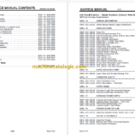
SERVICE MANUAL 1212 KEYSHEET
Book 1110 1 of 2
248 HYLAB 5 Series — Master Keysheet (Crawler, Third Drum, & Boom)
(N5 Prefix On Crane Serial Number)
AREA 00 GENERAL INFORMATION
********************************************************************************************
SM00—000—000.00 Service Manual General Usage & Instructions
AREA 02 CRAWLER LOWER
********************************************************************************************
SM02—001—002.00 Track, R & I
SM02—003—030.00 Track Drive And Sprocket, R & I
SM02—003—031.00 Track Drive Planetary, Brake, & Motor, Recondition
SM02—004—012.00 Take—Up Roller, R & I
SM02—004—013.00 Take—Up Roller, Recondition
SM02—004—014.00 Sealed Take—Up Roller, Recondition
SM02—004—015.00 Sealed Take—Up Roller, R & I
SM02—005—014.00 Track Roller, R & I
SM02—005—015.00 Sealed Track Roller, Recondition
SM02—007—004.00 Track Adjustment Cylinder, Recondition
SM02—007—005.00 Track Adjustment Hand Pump, Recondition
SM02—010—022.00 Hydraulic System Cleaning
SM02—010—028.00 Hydraulic Components, R & I
SM02—011—017.00 Travel Motor, R & I
SM02—014—001.00 Jack Cylinder, R & I
SM02—014—002.00 Jack Cylinder, Recondition
SM02—014—003.00 Jack Cylinder Control Valve, R & I
SM02—014—004.00 Control Valve, Recondition (Jack Cylinder)
SM02—014—005.00 Jack Cylinder Lock Valve, R & I
SM02—014—006.00 Jack Cylinder Lock Valve, Recondition
AREA 03 UPPER REVOLVING FRAME
********************************************************************************************
SM03—001—059.00 Upper Frame And Turntable Bearing, R & I
AREA 05 HORIZONTAL SHAFTS
********************************************************************************************
SM05—005—015.00 Third Drum Winch, R & I
SM05—005—016.00 Winch, Recondition — Third Drum
AREA 06 UPPER ENGINE
********************************************************************************************
SM06—044—001.00 Generator & Light Plant Schematic Diagram
SM06—047—000.00 Electrical System Wire Identification Code
AREA 07 HYDRAULIC POWER SUPPLY
********************************************************************************************
SM07—000—000.00 Hydraulic Schematic Diagram Symbol Legend
SM07—006—056.00 Hydraulic Motor, Recondition — Third Drum
SM07—006—070.00 Third Drum Hydraulic Motor, R & I
SM07—018—001.00 Hydraulic System Tube Fittings
AREA 09 TUBULAR BOOM, FLY, & JIB
********************************************************************************************
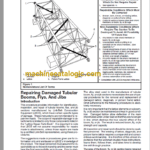
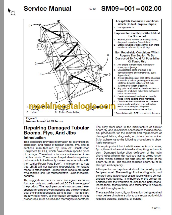
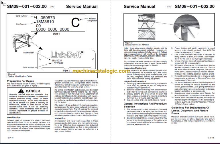
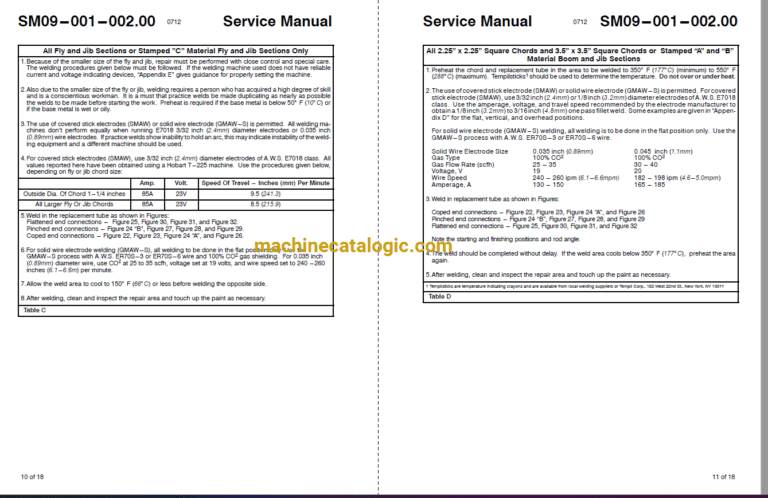
SM09—001—002.00 Repairing Damaged Tubular Booms, Flys, & Jibs
AREA 18 SPECIAL ATTACHMENTS
********************************************************************************************
SM18—000—001.00 Capscrew Torques
SM18—000—002.00 Bearing, Gear, Shaft, & Housing Inspection
SM18—000—003.00 Crane System Schematics