Format: PDF (Printable Document)
File Language: English
Brand: Link Belt Crane
Model: HC248H
Type of Document: Service Manual
$ 55
Section-O General
Equipment Layout
Section-I Upper Mechanism
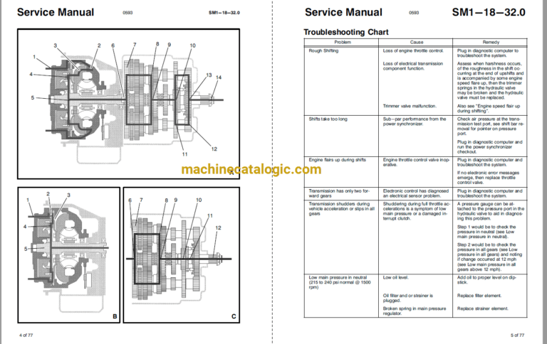
Power Transmission System •
Front And Rear Drum Shaft Structure And Outline
Front And Rear Drum Shatt Maintenance Chart
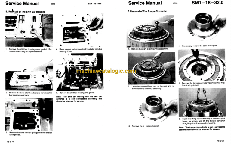
Front And Rear Drum Shaft Disassembly And Reassembly
Boom Hoist Drum Shaft Structure And Outline —
Boom Hoist Drum Shaft Maintenance Chart —
Boom Hoist Drum Shaft Disassembly And Reassembly
Clutch Structure And Outline (1 -Cylinder Type) –
Clutch Maintenance Chart 1 •Cylinder Type)
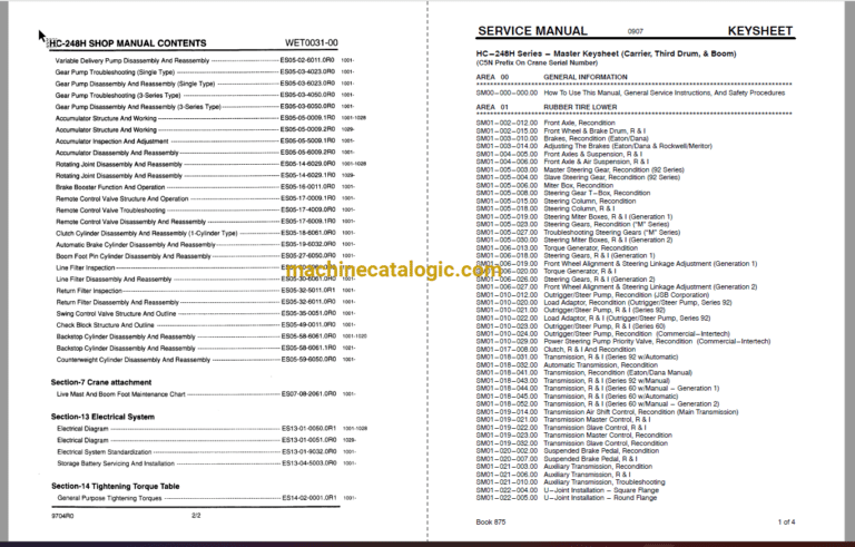
Clutch Troubleshooting (1 •CylincÉr Type)
Clutch Disassembly And Reassembly (1 -Cylinder Type)
Swing Mechanism Maintenance Chart
Turntable Beanng Maintenance Chart —
Turntable Bearing Inspection And Adjustment
Power Divider (Pump Splitter) Maintenance Chart
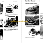
Power Divider (Pump Splitter) Disassembly And Reassembly
Section-3 Control System
Front And Rear Drum Maintenance Chart
Front And Rear Drum Brakes Control Inspection And Adjustment
Front And Rear Drum Brakes Control Disassembly And Reassembly
Front, Rear And Boom Hoist Drum Lock Pawl Control Maintenance Chart •
Section-4 Hydraulic System
Hydraulic Circuit OutEne –
Hydraulic Circuit Outline
Hydraulic Circuit Outline
Hydraulic Circuit Pressure Adjustment –
Hydraulic Circuit Pressure Adjustment •
Hydraulic Circuit Pressure Adjustment
Section-5 Hydraulic Unit
Variable Delivery Pump Outline And Structure
Vanable Delivery Pump Troubleshooting
Variable Delivery Pump Disassen%ly Reassenbly —
Gear Pump Troubleshooting (Single Type)
Gear Pump Disassembly And Reassernbly (Single Type)
Gear Pump Troubleshooting (3•Series Type)
Gear Pump Disassembly And Reassembly (3.Series Type) —
Acarnulator Structure And Working —
Accumulator Structure Working
Accumulator Inspection And Adjustment —
Accumulator Disassembly And Reassembly —
Rotating Joint Disassembly Reassembly
Rotating Joint Disassembly Reassembly
Brake Booster Function And Operation
Remote Control Valve Structure And Operation •
Remote Control Valve Troubleshooting
Remote Control Valve Disassembly And Reassembly
Clutch Cylinder Disassembly Ard Reassernbly (1 -Cylinder Type)
Automatic Brake Cylinder Disassembly And Reassembly
Boom Foot Pin Cylinder Disassembly And Reassembly
Line Filter Inspection —
Line Filter Disassembly And Reassembly
Return Filter
Return Filter Disassembly And Reassembly — –
Swing Control Valve Structure And Outline
Check Block Structure And Outline
Cylirder Disassembly And Reassembly
Backstop Cylinder Disassembly And Reassembly
Counterweight Cylinder Disassembly And Reassembly
Section-7 Crane attachment
Live Mast And Boom Foot Maintenance Chart
Section-13 Electrical System
Electrical Diagram —
Electrical Diagram
Electrical System Standardization
Storage Battery Servicing And Installation — —
Section-14 Tightening Torque Table
General purpose Tightening Torques
