Format: PDF (Printable Document)
File Language: English
File Pages: 82
File Size: 38.87 MB (Speed Download Link)
Brand: Manitowoc
Model: RCL Technology Crane
Type of Document: Participants Documents
$ 40
On a Manitowoc crane working on high-rise jobs or plant shutdowns, the RCL (Rated Capacity Limiter) is what keeps the lifting side honest. This document helps you understand and work with the electronic brain behind that system, especially the EKS unit, sensors, and CAN bus communication. In the field, I’d use it when the crane is throwing RCL faults, the load chart isn’t displaying correctly, or a pressure sensor reading doesn’t match what I’m seeing on the boom or in the hydraulics.
Applications & Use Cases
FAQ
Q: Can I keep a digital copy of this on a tablet in the cab?
A: Yes, it’s practical to use digitally so you can zoom in on wiring and connection details while you’re testing.
Q: Is this worth printing in full?
A: Printing the key connection and layout pages is handy for tracing circuits and making notes during troubleshooting.
Safety Note
Always de-energize and secure the crane before opening panels, probing circuits, or disturbing any RCL components.
Table of Contents
1.0 EKS 4
1.1 Connections EKS4 4
1.2 CAN bus 5
1.3 Interior view 6
1.4 CPU Board EKS4 7
1.5 Pressure sensors 8
1.6 Length sensors 9
1.7 Angle sensors 10
1.8 Bus node card 11
1.9 EKS4 – Inputs 12
1.10 EKS4 – Outputs 13
1.11 Resistor card 14
2.0 EKS 5
2.1 Connections EKS5 15
2.2 CPU Board EKS5 16
2.3 CAN bus 17
2.4 New angle card 18
2.5 EKS5: Light display 19
2.6 EKS5: Graphic display 20
2.7 Lifting limit switch EKS5 21
3.0 Appendix
3.1 CPU, RAM & Co. 22
4. EKS 4 Rated Capacity Indicator (GMK 5100) 24
5. EKS 5 Rated Capacity Indicator (GMK 5130-1) 47
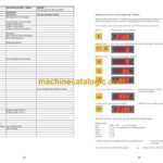
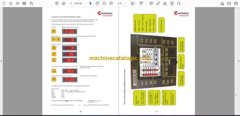
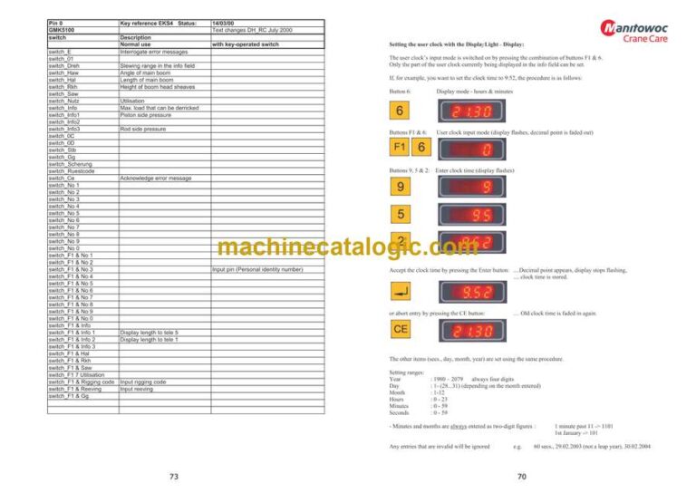
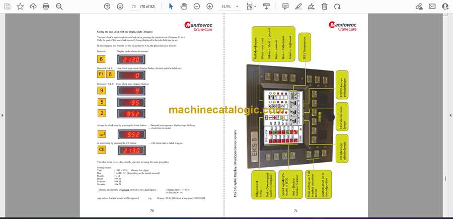
6. EKS 5 Light User Clock 69
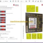
7. EKS 5 Graphic Display Sensor Screen 71
8. EKS 4 Keyboard Layout 73
9. EKS 5 Light Keyboard Layout 75

