Format: Interactive PDF (Printable Document)
File Language: Operation Manual: English, Maintenance Manual: English, Technical Manual: English, Parts Manual: English
File Size: 233.96 MB (Speed Download Link)
Brand: Sandvik
Model: DD311-40 Drilling Rig
No: L11D5317
Type of Document: Full Toolman Manual (Service, Operator, Maintenance Manual and Parts Catalog)
The language on the cover page and the product itself may differ
$ 150
BÖLÜM 01 GENERAL INFORMATIONS
INFORMATIONS GENERAL
GENEL BİLGİLER
BÖLÜM 02 LUBRICATION
LUBRIFICATION
YAĞLAMA
BÖLÜM 03 ROCK DRILL
PERFORATEUR
KAYA DELİCİ
BÖLÜM 04 DRILL FEED – TURRET
GLISSIERE – TOURELLE
DELME BESLEMELİ TARET
BÖLÜM 05 BOOM
BRAS
ÇUBUK
BÖLÜM 06 HYDRAULIC COMPONENTS
COMPOSANTS HYDRAULIQUE
HİDROLİK BİLEŞENLER
BÖLÜM 07 TRAMMING COMPONENTS
CHAINE CINEMATIQUE
TAPANLAMA BİLEŞENLERİ
BÖLÜM 08 DIESEL ENGINE
GROUPE DIESEL
DİZEL MOTORU
BÖLÜM 09 AIR FLUSHING CIRCUIT
CIRCUIT INJECTION AIR HAVA PÜSKÜRTME DEVRESİ
BÖLÜM 10 WATER FLUSHING CIRCUIT
CIRCUIT INJECTION EAU
SU YIKAMA DEVRESİ
BÖLÜM 11 ELECTRIC EQUIPMENT
EQUIPEMENT ELECTRIQUE
ELEKTRİK DONANIMI
BÖLÜM 12 OPTIONAL EQUIPMENT
EQUIPMENT OPTIONNEL
İSTEĞE BAĞLI DONANIM
SECTION 1 HYDRAULIC AND ELECTRIC DIAGRAMS
SCHÉMAS HYDRAULIQUES ET ÉLECTRIQUES
SECTION 2 ROCK DRILL, FLUSHING HEAD
PERFORATEUR, TÊTE D’INJECTION
SECTION 3 DRILL FEED
GLISSIÈRE
SECTION 4 BOOM
BRAS
SECTION 5 DRILLING COMPARTMENT
POSTE DE FORATION
SECTION 6 DRILLING HYDRAULIC COMPONENTS
COMPOSANTS HYDRAULIQUES DE FORATION
SECTION 7 TRAMMING COMPARTMENT
POSTE DE CONDUITE
SECTION 8 DIESEL POWER PACK
GROUPE THERMO HYDRAULIQUE
SECTION 9 POWER TRAIN
CHAINE CINÉMATIQUE
SECTION 10 ELECTRIC POWER PACK
GROUPE ÉLECTRO HYDRAULIQUE
SECTION 11 ELECTRIC COMPONENTS
COMPOSANTS ÉLECTRIQUES
SECTION 12 WATER FLUSHING CIRCUIT
CIRCUIT INJECTION EAU
SECTION 13 COMPRESSED AIR CIRCUIT
CIRCUIT D’AIR COMPRIME
SECTION 14 HYDRAULIC TANKS
RÉSERVOIRS HYDRAULIQUES
SECTION 15 CARRIER
PORTEUR
SECTION 16 CANOPY
TOIT DE PROTECTION
SECTION 17 OPTIONAL EQUIPMENTS
OPTIONS
THIS SECTION DOES NOT CONCERN YOUR MACHINE
CETTE SECTION NE CONCERNE PAS VOTRE MACHINE
SECTION 18 HYDRAULIC HOSES
FLEXIBLES HYDRAULIQUES
SECTION 19 SPECIAL EQUIPMENTS
ÉQUIPEMENTS SPÉCIAUX
1. INTRODUCTION………………………………………………………………………………… 8
1.1. The purpose of instructions……………………………………………………. 8
1.2. Identification ………………………………………………………………………….. 8
1.2.1. Product type and serial number ………………………………………………………. 8
1.2.2. Product manufacturer …………………………………………………………………….. 9
1.2.3. Manuals ……………………………………………………………………………………….. 9
1.2.4. How to identify the correct manual for the product ……………………………… 9
1.2.5. Validity of the manuals …………………………………………………………………. 10
1.2.6. Marking of the product …………………………………………………………………. 11
1.3. Copyright notice…………………………………………………………………… 12
1.4. Definitions …………………………………………………………………………… 12
2. SAFETY AND ENVIRONMENTAL INSTRUCTIONS…………………………….. 16
2.1. Safety labels, safety messages and signals…………………………… 16
2.1.1. Signal words ……………………………………………………………………………….. 16
2.1.2. General hazard symbol ………………………………………………………………… 16
2.1.3. Mandatory actions symbols …………………………………………………………… 17
2.1.4. Prohibited actions symbols …………………………………………………………… 18
2.1.5. Hazard symbols ………………………………………………………………………….. 19
2.1.6. Labels on product ………………………………………………………………………… 20
2.2. User obligations …………………………………………………………………… 26
2.2.1. Managing work related hazards …………………………………………………….. 27
2.2.2. Scheduled safety inspections and preventive maintenance ………………. 27
2.2.3. Personnal protective equipment …………………………………………………….. 28
2.3. Product Limitations………………………………………………………………. 29
2.3.1. Intended use ………………………………………………………………………………. 29
2.3.2. Foreseeable misuse …………………………………………………………………….. 29
2.3.3. Prohibited use …………………………………………………………………………….. 30
2.3.4. Centre of gravity ………………………………………………………………………….. 31
2.3.5. Maximum inclination angles during tramming and parking ………………… 32
2.3.6. Maximum inclinations angles during operating ………………………………….32
2.3.7. Modifications ………………………………………………………………………………..33
2.4. Hazard zones ……………………………………………………………………….. 34
2.4.1. During drilling and boom movements ………………………………………………36
2.4.2. Operator visibility ………………………………………………………………………….37
2.4.3. Noise ………………………………………………………………………………………….39
2.4.4. Acceleration …………………………………………………………………………………39
2.4.5. Dust ……………………………………………………………………………………………40
2.5. Safeguarding ……………………………………………………………………….. 41
2.5.1. Guards ………………………………………………………………………………………..41
2.5.2. Safety telescopic canopy ……………………………………………………………….42
2.6. Complementary protective measures ……………………………………. 43
2.6.1. Use of emergency stop function ……………………………………………………..43
2.6.2. Emergency exit …………………………………………………………………………….48
2.6.3. Safe access to machinery and three point support ……………………………49
2.6.4. Fire risk control measures ……………………………………………………………..50
2.7. Protection against emission hazards…………………………………….. 57
2.7.1. Noise ………………………………………………………………………………………….57
2.7.2. Vibration ……………………………………………………………………………………..57
2.7.3. Dust ……………………………………………………………………………………………58
2.8. Emergency procedures and methods for unblocking…………….. 58
2.9. Safety considerations for maintenance …………………………………. 59
2.10. Environment ………………………………………………………………………… 60
2.10.1. Decommissioning ……………………………………………………………………….60
2.10.2. Dismantling ………………………………………………………………………………..61
2.10.3. Disposal …………………………………………………………………………………….61
2.11. Potential hazards related hazard identified by the user ………….. 62
2.12. Incident reporting…………………………………………………………………. 62
3. INTRODUCTION TO PRODUCT………………………………………………………… 64
3.1. Machine orientation ……………………………………………………………… 64
3.2. Main circuits and components………………………………………………. 64
Copyright © Sandvik Mining and Construction
ID: 7849 5128 en – D-06-07-2011 GP-RB-GP
OPERATOR’S MANUAL DD311-40 / 40C
5 (206)
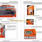
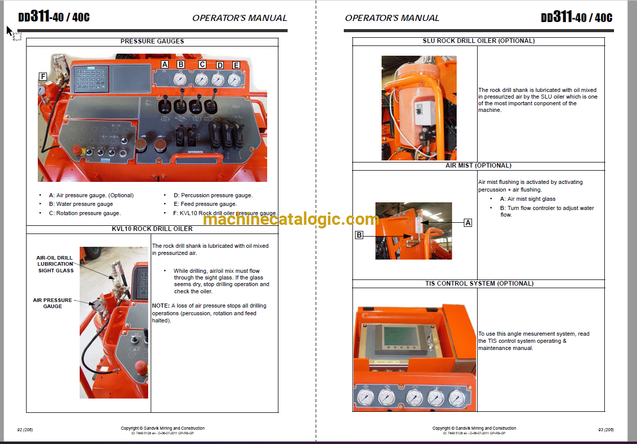
3.3. Instruments and controls ……………………………………………………… 77
3.3.1. Tramming compartment ……………………………………………………………….. 77
3.3.2. Drilling compartment ……………………………………………………………………. 86
3.4. Main fuses and circuit breakers…………………………………………….. 99
4. OPERATING INSTRUCTIONS…………………………………………………………. 106
4.1. Operator instructions………………………………………………………….. 106
4.2. Main safety hazards in use or maintenance work…………………. 107
4.3. Electric system – Operator’s safety instruction…………………….. 109
4.4. Assembly and checking of a new machine ………………………….. 111
4.5. Daily checks……………………………………………………………………….. 112
4.5.1. Routine checks before starting a shift …………………………………………… 114
4.6. Brakes tests ……………………………………………………………………….. 126
4.7. Tramming …………………………………………………………………………. 130
4.7.1. Machine in tramming position and parking …………………………………….. 130
4.7.2. Starting the engine …………………………………………………………………….. 132
4.7.3. Electric cable …………………………………………………………………………….. 137
4.7.4. Moving the machine …………………………………………………………………… 138
4.7.5. Parking the machine ………………………………………………………………….. 140
4.8. Drilling …………………………………………………………………………. 141
4.8.1. Setting-up the machine in the drift ……………………………………………….. 141
4.8.2. Use of stabilizers ……………………………………………………………………….. 143
4.8.3. Electric power ……………………………………………………………………………. 144
4.8.4. Parallelism setting ……………………………………………………………………… 146
4.8.5. Setting drill feed TTF and TFX …………………………………………………….. 148
4.8.6. Collaring a hole …………………………………………………………………………. 150
4.8.7. Normal drilling …………………………………………………………………………… 150
4.8.8. Drilling imperatives …………………………………………………………………….. 152
4.8.9. Removing the drill bit ………………………………………………………………….. 152
4.8.10. Ending a shift ………………………………………………………………………….. 154
5. SPECIAL INSTRUCTIONS………………………………………………………………. 156
5.1. Short distance towing…………………………………………………………. 156
5.2. Long distance towing …………………………………………………………. 158
5.2.1. Towing with the engine in operating condition …………………………………158
5.2.2. Towing with a faulty engine ………………………………………………………….158
5.3. Transporting ………………………………………………………………………. 159
5.3.1. Transportation on a platform ………………………………………………………..159
5.4. Lifting methods and lifting points ……………………………………….. 160
5.5. Storing instructions ……………………………………………………………. 161
5.6. Wash the rig……………………………………………………………………….. 162
6. TROUBLESHOOTING…………………………………………………………………….. 164
6.1. Deutz electronic regulator: EMR 2 (optional) ……………………….. 165
6.1.1. Description of functions ……………………………………………………………….165
6.1.2. Troubleshooting ………………………………………………………………………….166
7. TECHNICAL SPECIFICATIONS ………………………………………………………. 170
![Sandvik DD311-40 Drilling Rig Full Documents (Service, Operator, Maintenance Manual and Parts Catalog) [L11D5317]](https://machinecatalogic.com/wp-content/uploads/2025/05/115-13-150x150.png.webp)
![Sandvik DD311-40 Drilling Rig Full Documents (Service, Operator, Maintenance Manual and Parts Catalog) [L11D5317]](https://machinecatalogic.com/wp-content/uploads/2025/05/115-13.png.webp)

